 Small batches, high standards. Our rapid prototyping service makes validation faster and easier —
  EN
EN

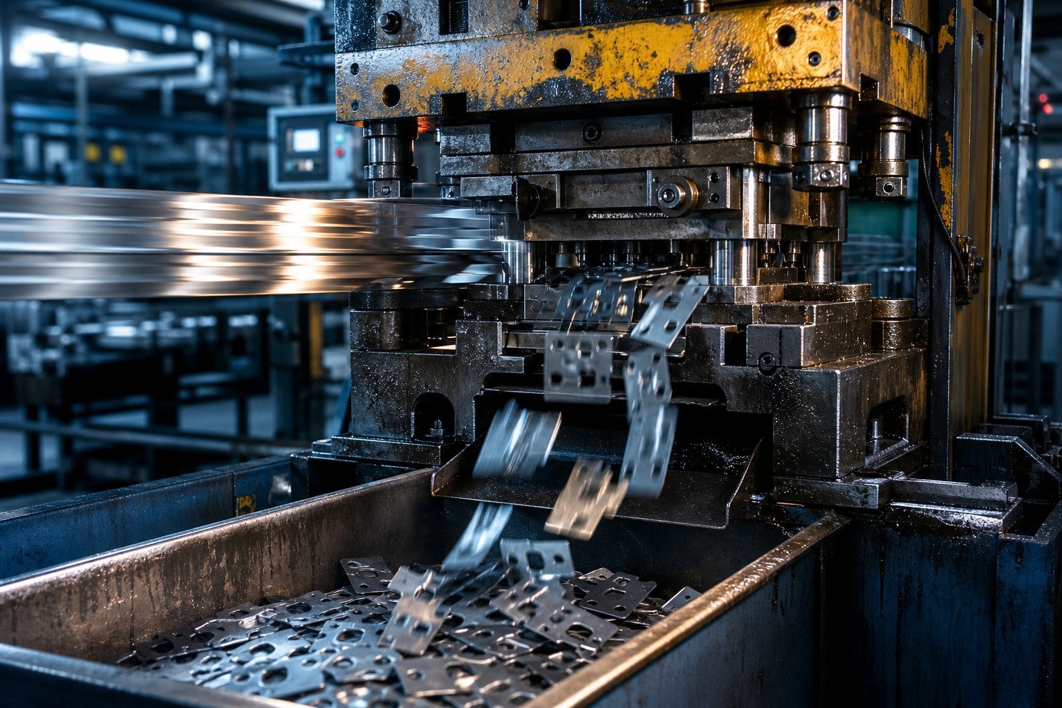
Material Suitability for High Speed Machining
Thermal Conductivity and Machinability Trade-offs in Aluminum, Titanium, and Inconel
Thermal conductivity is the dominant material property governing heat evacuation during high speed machining (HSM), directly influencing tool life, achievable cutting speeds, and surface integrity. Aluminum alloys—such as 6061-T6—exhibit high thermal conductivity (~150–170 W/m·K), enabling rapid heat dissipation from the cutting zone. This allows stable operation at speeds exceeding 1,000 m/min and delivers a machinability rating classified as excellent. However, this efficiency demands robust chip control: re-cutting fine, sticky chips can cause smearing and poor surface finish.
Titanium Ti-6Al-4V presents the opposite challenge, with extremely low thermal conductivity (~7 W/m·K). Over 80% of generated heat remains concentrated in the tool–chip interface, accelerating wear and promoting work hardening. Practical HSM is therefore constrained to 60–90 m/min and requires sharp, rigid carbide inserts paired with high-pressure through-tool coolant to mitigate thermal buildup.
Inconel 718 (conductivity ~11 W/m·K) compounds these difficulties—not only does it retain heat inefficiently, but it also exhibits severe strain hardening and high flow stress. Cutting speeds rarely exceed 30–60 m/min, and success hinges on rigid setups, ceramic or advanced nano-grain carbide tools, and process innovations like cryogenic cooling or adaptive toolpath strategies pioneered in aerospace and power-generation applications.
| Material (Example) | Thermal Conductivity (W/m·K) | Typical HSC Range (m/min) | Machinability Rating | Primary Trade-off |
|---|---|---|---|---|
| Aluminum 6061-T6 | 150–170 | 1000–3000 | Excellent | Excellent speed, but chip evacuation critical |
| Titanium Ti-6Al-4V | 7 | 60–90 | Poor | Low conductivity accelerates tool wear; demands special coolant |
| Inconel 718 | 11 | 30–60 | Very poor | Pronounced work hardening; high forces required |
Debunking the Hardened Steel Myth: When and How It Can Be Used in High Speed Machining
The long-held assumption that hardened steels (≥45 HRC) are incompatible with high speed machining has been invalidated by advances in tool materials and process engineering. Polycrystalline cubic boron nitride (PCBN) and next-generation AlTiN-coated carbides now enable dry or near-dry HSM at 200–400 m/min in pre-hardened steels—including case-hardened 8620 (60 HRC)—achieving surface finishes below 0.8 µm Ra without coolant. PCBN’s exceptional hot hardness (>1,200 °C) and thermal shock resistance, combined with AlTiN’s low friction coefficient, significantly reduce heat transfer to the tool substrate and extend edge life.
Critical to success is dynamic stability: stiff machine-tool-workpiece systems suppress chatter, while light radial engagements (≤15% of tool diameter) limit cutting forces and prevent deflection. Industrial validation confirms that CBN tools deliver up to three times the tool life of conventional carbide in hardened steel HSM—proving that material hardness alone no longer defines feasibility, provided tool selection, coating architecture, and parameter strategy are aligned.
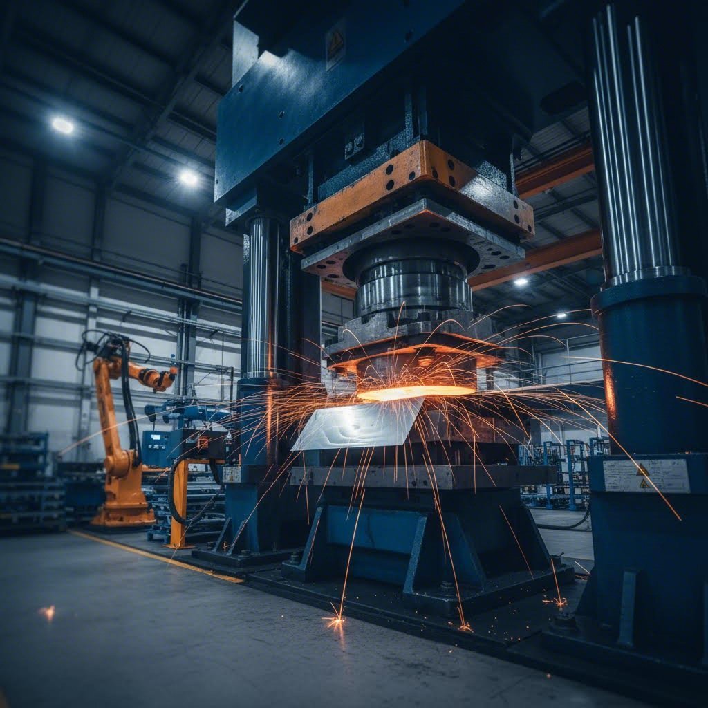
Geometric Stability and Dynamic Response at High Spindle Speeds
In high speed machining, geometric stability emerges not just from static rigidity—but from the integrated dynamic behavior of the entire system: spindle, toolholder, tool, fixture, and workpiece. As rotational speeds increase, even minute imbalances or structural resonances can amplify into destructive vibrations, compromising dimensional fidelity and surface quality—especially in thin-walled or flexible components where natural frequencies often overlap operational spindle ranges.
Thin-Walled Features, Resonance Avoidance, and Modal Damping Strategies
Thin-walled geometries behave like lightly damped plates, making them highly susceptible to resonance when spindle harmonics coincide with their modal frequencies. The most effective mitigation begins at design: modal analysis identifies “danger zones” in the speed spectrum—spindle RPM bands that must be avoided entirely. When design constraints prohibit speed avoidance (e.g., due to production cycle time or surface finish requirements), damping becomes essential.
Passive solutions include tuned-mass dampers embedded in fixtures and viscoelastic interface layers that absorb vibrational energy before it couples into the part. On the machine side, direct-drive spindles eliminate belt-induced harmonics, while precision bearing preload adjustments shift system stiffness—and thus resonance peaks—away from operating speeds. Emerging active approaches, such as electro-rheological fluid mounts, offer real-time, closed-loop vibration suppression. Together, these strategies convert inherently unstable thin-walled features into geometrically reliable components capable of sustaining the dynamic loads inherent to high speed machining.
Precision Requirements: Tolerances, Surface Finish, and High Speed Machining Parameters
Interplay of Cutting Speed, Feed Rate, and Chip Load on Dimensional Accuracy and Ra Values
Achieving tight tolerances and fine surface finishes in high speed machining requires deliberate balancing of cutting speed, feed rate, and chip load—each parameter exerts distinct, interdependent effects on cutting forces, thermal expansion, tool deflection, and vibration. Higher cutting speeds generally improve surface finish by reducing built-up edge formation and stabilizing shear zone behavior—but they also elevate thermal gradients, risking dimensional drift in precision-critical features. Conversely, elevated feed rates increase mechanical loading, amplifying tool deflection and initiating chatter—degrading both positional accuracy and Ra values.
Chip load—the thickness of material removed per tooth—acts as a key modulator: lighter loads favor surface integrity and dimensional stability, while heavier loads push the system toward chatter thresholds, particularly in flexible setups. Industrial experience, corroborated by authoritative machining handbooks, demonstrates consistent trends:
| Parameter Change | Effect on Dimensional Accuracy | Effect on Ra (Surface Roughness) |
|---|---|---|
| Cutting speed ↑ (e.g., 300→600 m/min) | Slight improvement due to reduced cutting forces, but risk of thermal drift | Ra may decrease by 10 ‑ 20% if tool wear stable |
| Feed rate ↑ (e.g., 0.1→0.2 mm/rev) | Error grows linearly with tool deflection; can double deviation | Ra increases roughly as (feed)²; typical jump from 1.6 µm to 3.2 µm |
| Chip load ↑ (e.g., 0.05→0.1 mm/tooth) | Chatter threshold approached, degrading positional accuracy | Ra rises by 30 ‑ 50% due to larger scallops |
For precision-critical parts—such as optical mounts or aerospace housings—tight ±0.005 mm tolerances and Ra ≤ 0.8 µm typically require moderate cutting speeds, low feed rates, and conservative chip loads. In contrast, roughing operations prioritize material removal rate over surface quality, accepting higher Ra values and looser tolerances by increasing feed and chip load within the system’s stability envelope. Ultimately, parameter selection is not arbitrary—it reflects an intentional alignment between functional requirements, part geometry, and the physical limits of the machining system.
FAQ Section
Q: What is the importance of thermal conductivity in high speed machining?
A: Thermal conductivity directly impacts heat evacuation during machining, influencing tool life, cutting speeds, and surface finish. Materials like aluminum have high conductivity, ensuring efficient heat dissipation, while titanium and Inconel pose challenges due to their low conductivity.
Q: Can hardened steels be processed using high speed machining?
A: Yes, with the advent of tools like polycrystalline cubic boron nitride (PCBN) and advanced coatings, hardened steels can be machined at high speeds with improved tool life and fine surface finishes.
Q: How can resonance issues be addressed in thin-walled machining?
A: Resonance can be mitigated through modal analysis to avoid critical RPM bands, damping strategies like tuned-mass dampers, and advanced machine designs including direct-drive spindles and adaptive fluid mounts.
Q: What parameters influence precision and surface finish in high speed machining?
A: Cutting speed, feed rate, and chip load are critical. Higher speeds improve surface finish but risk thermal drift, while higher feed rates can degrade accuracy. Balancing chip load affects dimensional integrity and surface roughness.