 Small batches, high standards. Our rapid prototyping service makes validation faster and easier —
  EN
EN

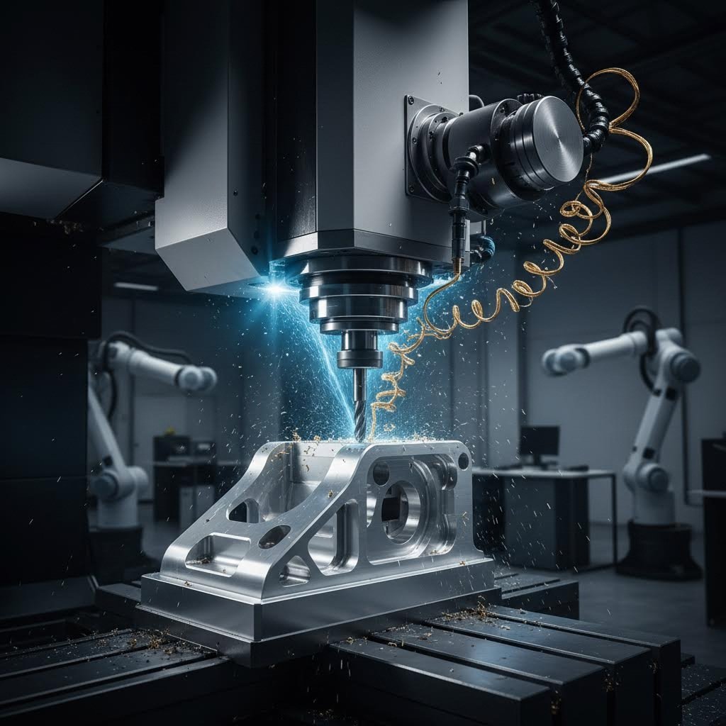
Identify Root Causes of Dimensional Errors in Repeated Cutting
Workpiece Misalignment and Fixturing Instability
Even minor workpiece shifts can rapidly amplify dimensional errors and undermine cutting consistency. According to the 2023 Global Machining Accuracy Report, 45–55% of in-process variation in serial machining stems from unstable fixturing or poor initial alignment. Common contributors include worn locating pins, uneven clamping pressure, and vibration-induced micro-slips. When a fixture deforms slightly with each load cycle, the part datum drifts—causing the toolpath to diverge from the intended geometry. Operators often miss this drift until a batch fails in-line inspection.
Hydraulic and pneumatic clamping systems are especially vulnerable to pressure decay over a shift: a drop of just 0.2 MPa can allow 10–20 µm of workpiece lift—enough to violate tight tolerances. Stacked tolerances from multiple re-clamping setups further compound the error. Simple verification—such as checking repeatability with a dial indicator across five consecutive load cycles—can expose instability before scrap is generated. Addressing these foundational issues eliminates the largest source of random dimensional variation.
Cumulative Parameter Drift Across Cutting Cycles
A second major class of dimensional errors arises from slow, progressive drift caused by accumulating micro-changes during repeated cutting. Tool wear is the most familiar driver: on a CNC lathe producing steel shafts, 0.1 mm of flank wear can shift diameters by ~0.02 mm per 40 parts—a trend easily missed before statistical process control (SPC) alarms activate (2022 AMT Shop-Floor Study). Thermal growth in ballscrews and spindle shafts produces a similar effect; as the machining center warms during its first hour of operation, positioning can drift 8–12 µm, stretching bore patterns until thermal compensation maps update.
Less obvious—but equally consequential—is parameter creep. Slightly aggressive servo tuning may maintain accuracy for short runs, but repeated cutting forces cause micro-backlash to accumulate, increasing following error over time. Feed-rate overrides introduced to reduce cycle time also alter cutting temperatures, affecting chip formation and tool deflection. These interdependent drifts are best detected by trend-monitoring key features across an entire production shift—not just first-off and last-off parts. Tracking the rate of change, rather than absolute error alone, clarifies whether real-time compensation or preventive maintenance is the appropriate corrective action.
Optimize CNC Parameters to Reduce Dimensional Errors in Repeated Cutting
Balancing Feed Rate, Spindle Speed, and Depth of Cut for Thermal Consistency
Every cutting cycle generates heat that distorts both tool and workpiece. Unbalanced feed rate, spindle speed, and depth of cut create thermal gradients that drive cumulative dimensional drift—up to 20 µm per 100 parts. A 2022 study in the Journal of Manufacturing Processes found that reducing spindle speed by 15% while setting depth of cut to 0.5 mm reduced the heat-affected zone width by 38%, directly improving dimensional stability across repeated runs. Feed rate must complement this balance: too aggressive a feed increases friction and temperature rise; too conservative a rate prolongs tool engagement and invites thermal soak-in. The optimal combination sustains steady-state tool temperature, minimizing transient expansion that leads to inconsistent part dimensions. Field data from a leading automotive supplier showed that fine-tuning these three parameters eliminated out-of-tolerance variations in 94% of consecutive batches—confirming thermal consistency as the linchpin of repeatable precision.
DOE-Validated Parameter Tuning: 32% Reduction in Dimensional Variation
A structured Design of Experiments (DOE) approach transforms subjective tuning into data-driven certainty. In one aerospace component line, a full-factorial DOE evaluated six combinations of feed rate, spindle speed, and depth of cut while measuring final bore diameter. Analysis revealed that a counterintuitive set—high spindle speed, moderate feed, and shallow depth—simultaneously minimized vibration, tool deflection, and thermal drift. The validated parameters reduced dimensional variation by 32% compared to prior settings, raising CpK from 1.15 to 1.67 (Machine Tool Engineering, 2023). DOE’s strength lies in exposing interaction effects invisible to single-factor trials—for instance, how a 10% speed increase improves accuracy only when paired with a shallower cut, avoiding the thermal spike that would otherwise distort dimensions. This method enables manufacturers to lock in a robust, long-run parameter recipe—sustaining tight tolerances across thousands of cycles without constant operator intervention.
Mitigate Thermal Deformation and Measurement Uncertainty in High-Volume Cutting
Real-Time Thermal Compensation Using Embedded Sensor Networks
In high-volume cutting, thermal expansion of the workpiece, tool, and machine structure remains a dominant source of dimensional error. For example, a 20°C ambient rise can cause a 100 mm aluminum part to expand by 0.46 mm—far exceeding typical tolerance bands. Real-time thermal compensation using embedded sensor networks addresses this by placing thermocouples or RTDs at critical locations such as the spindle nose, guideways, and fixture base. These sensors stream temperature data to the CNC controller, which dynamically adjusts tool offsets in real time. Advanced algorithms neutralize thermal drift with sub-micron resolution, reducing positional errors to within a few microns and sustaining part-to-part consistency below ±5 µm across production runs. Deployments have cut dimensional errors by up to 40%, significantly reducing reliance on post-process inspection and rework—boosting yield and throughput in high-volume precision machining.
FAQ
What are the main causes of dimensional errors during repeated cutting?
The primary causes include workpiece misalignment, fixturing instability, tool wear, thermal growth, and parameter drift caused by aggressive servo tuning and feed-rate adjustments.
How can thermal consistency improve dimensional stability in CNC machining?
Balancing feed rate, spindle speed, and depth of cut creates steady-state tool temperature and minimizes transient heat effects, thereby reducing dimensional inconsistencies.
What is a Design of Experiments (DOE) approach and how does it help?
DOE is a structured method of testing various parameter combinations to identify the optimal settings. It helps exposure interaction effects among variables, reducing dimensional variations and improving manufacturing consistency.
How does real-time thermal compensation work?
Real-time thermal compensation uses embedded sensor networks to monitor temperature changes in critical components like spindles and fixtures. The CNC controller adjusts tool offsets dynamically to account for thermal expansion and maintain dimensional accuracy.