 Small batches, high standards. Our rapid prototyping service makes validation faster and easier —
  EN
EN

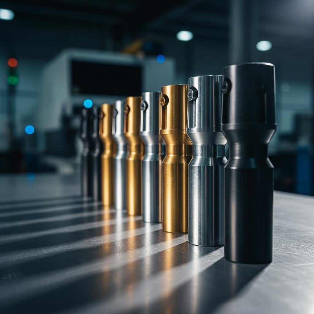
Punching Clearance: The Primary Driver of Punching Edge Quality
Optimal Die Clearance Ranges for Common Metals
Punch-to-die clearance—the precisely defined gap between the punch and die cutting edges—is the single most influential factor in achieving consistent punching edge quality. This critical dimension directly governs material fracture behavior, punching force, and shear-zone morphology. Clearance is never arbitrary; it must be calculated as a percentage of material thickness, calibrated to the metal’s shear strength and ductility.
| Material | Recommended Clearance (% of thickness) |
|---|---|
| Mild Steel | 5 – 10 % |
| Stainless Steel | 5 – 7 % |
| Aluminum (soft) | 4 – 6 % |
| High-Strength Steel | 8 – 12 % |
These ranges reflect the balance required for clean, predictable fracture initiation. Mild steel tolerates a wider band due to its stable fracture plane, while stainless steel—tougher and more prone to work hardening—requires tighter control to minimize roll-over and burr. Using clearance at the upper end reduces punching force; lower values favor straighter cut surfaces. As outlined in engineered clearance guidelines from a leading manufacturer, optimal clearance ensures the upper and lower fractures meet precisely—enabling clean slug release with minimal burr and maximum edge integrity.
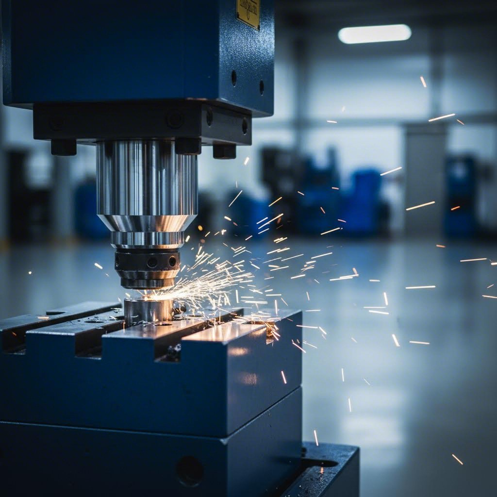
Consequences of Excessive or Insufficient Clearance on Edge Finish
Improper clearance fundamentally disrupts shear mechanics, degrading edge finish in predictable, opposing ways.
Too little clearance forces excessive plastic deformation before fracture, generating secondary shearing zones, higher loads, and localized heat. This accelerates punch galling and tool wear—and produces a torn, micro-cracked edge that appears acceptable visually but compromises part reliability in service.
Excessively large clearance delays fracture initiation, causing pronounced material roll-over before separation. The misaligned crack paths from punch and die fail to connect cleanly, resulting in tearing rather than shearing. The outcome is a large, jagged burr that impairs aesthetics, interferes with assembly, and risks damaging downstream tooling.
The ideal clearance is therefore a precise compromise: narrow enough to synchronize fracture propagation, yet wide enough to avoid secondary shearing. Because clearance must scale with material thickness, regular verification—especially during grade or gauge changes—is essential to sustain long-term punching edge quality.
Tool Condition and Alignment: Critical Factors in Consistent Punching Edge Quality
Even with perfect die clearance, consistent punching edge quality depends on tool sharpness and mechanical alignment. Progressive wear and subtle misalignments distort stress distribution across the shear zone, directly undermining cut surface integrity.
Edge Sharpness Degradation and Its Direct Impact on Burr Formation
Tool edges degrade through abrasion and micro-chipping. A dulled punch extrudes rather than shears, dramatically increasing burr height. For example, burr on mild steel can rise from 0.05 mm with a sharp tool to over 0.15 mm after 50,000 hits (Tool Life Study, 2023). This degradation also forces excessive roll-over before fracture, producing an uneven, ragged edge. Maintaining punch edge radii under 0.03 mm is critical—not only for burr control, but for dimensional repeatability and hole concentricity.
Radial and Vertical Misalignment Effects on Edge Taper and Roll-Over
Misalignment introduces unbalanced loading that skews the shear zone. A radial offset as small as 0.1 mm can induce taper angles exceeding 2° (Precision Punching Standards, 2022), pulling material downward asymmetrically and enlarging roll-over depth. Vertical misalignment—where the punch tip fails to contact the die face squarely—initiates fracture from one side only, further distorting edge geometry and amplifying burr height. Both conditions erode hole straightness and positional accuracy. Regular alignment verification using dial indicators—or laser-based systems on high-precision presses—is non-negotiable for maintaining edge quality across extended production runs.
Material Properties and Process Parameters That Influence Punching Edge Quality
Shear Angle, Rake Angle, and Die Geometry Effects on Fracture Initiation
Fracture initiation is governed not just by clearance, but by how force is applied geometrically. The shear angle on the punch or die localizes peak stress, guiding where and when cracking begins. A moderate shear angle (2–5°) lowers instantaneous load while enabling progressive separation—reducing secondary fracture and improving edge straightness.
Rake angle modifies the direction of the cutting force vector: a positive rake promotes tensile stress that encourages clean, early fracture; a negative rake increases compressive loading, delaying crack onset and exacerbating roll-over. Die geometry—including edge sharpness and land length—also controls fracture timing. A sharp die with a short land concentrates stress near the cutting edge, accelerating initiation—especially beneficial in ductile alloys. Conversely, a larger die radius spreads stress, retarding nucleation and increasing the risk of tearing. Together, these parameters define the fracture initiation zone—and their coordinated optimization is essential for repeatable edge quality.
Burr Formation Mechanisms Across Ductility Spectrums
Burr formation is intrinsically linked to a material’s plastic flow behavior before fracture. Highly ductile metals—like soft aluminum or copper—undergo significant plastic deformation under shear, producing prominent burrs when clearance or tool condition deviates from optimum. Brittle or hardened materials fracture more abruptly, yielding cleaner edges—but remain vulnerable to micro-chipping if tool edges are compromised or impact energy is poorly managed.
Critically, the ductile-to-brittle transition shifts with strain rate and temperature. Faster punch speeds or elevated temperatures can increase ductility, while cryogenic cooling or high-speed impacts may promote brittle response. Recognizing where a given material falls on this spectrum allows operators to fine-tune clearance, rake angle, and feed rate—not as fixed settings, but as interdependent variables—to suppress burr growth and maximize edge integrity.
FAQ
What is punching clearance?
Punching clearance refers to the gap between the punch and die cutting edges during the punching process. It plays a crucial role in controlling the quality of the punching edge, material fracture behavior, punching force, and shear-zone morphology.
Why does clearance differ for various metals?
Each material has unique shear strength and ductility. Recommended clearances vary to optimize punching performance and edge quality for specific metals like mild steel, stainless steel, or soft aluminum.
What happens if the clearance is too small or too large?
Too little clearance causes excessive plastic deformation, leading to torn edges, higher tool wear, and decreased part reliability. Excessive clearance, on the other hand, results in pronounced roll-over, jagged burrs, and irregular fractures.
How does tool sharpness affect punching quality?
Dull tools increase burr height and reduce edge quality by extruding rather than shearing material. Maintaining sharp tool edges ensures consistent punching performance and longevity of the tools.
What can cause misalignment during punching?
Misalignments, such as radial offsets or vertical discrepancies, can occur due to progressive wear or setup errors. They distort stress distribution, impair edge quality, and reduce product precision.