 Small batches, high standards. Our rapid prototyping service makes validation faster and easier —
  EN
EN

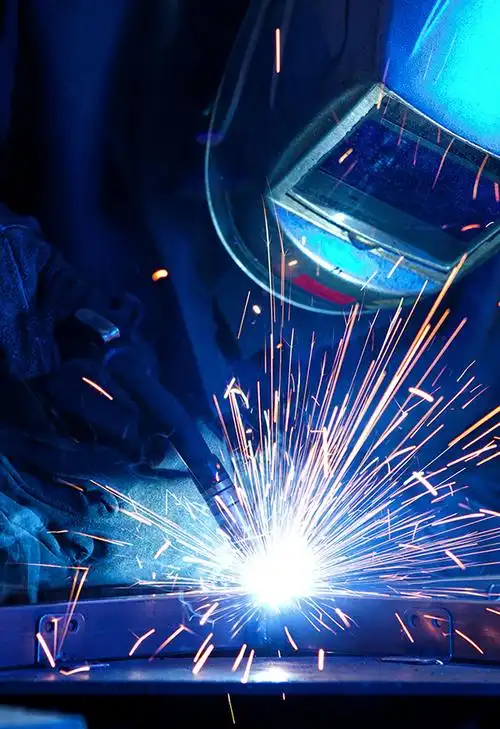
Root Causes of Weld Spatter: Arc Dynamics, Parameters, and Material Factors
Unstable Electric Arc Behavior Across GMAW Transfer Modes
Unstable electric arcs in GMAW manifest across globular, short-circuit, and spray transfer modes when electromagnetic forces fluctuate unpredictably—often triggered by voltage deviations exceeding ±5%. In globular transfer, large droplet formation imparts high momentum upon detachment, directly ejecting molten metal as spatter. Short-circuit welding suffers explosive transitions when contact time exceeds the optimal 20–30 ms window, causing violent arc re-ignition. Spray transfer becomes unstable when current falls below the critical threshold for consistent fine-droplet transfer—a condition documented in peer-reviewed arc stability studies. Collectively, these instabilities erode arc length control and significantly elevate spatter generation.
Voltage–Amperage Imbalance and Wire Feed Speed Mismatches
Spatter escalates sharply when power supply parameters deviate beyond the ±10% tolerance recommended for each filler metal classification. Excessive voltage elongates the arc, increasing energy dispersion and raising spatter rates by 25–40%, per metallurgical analyses published in Welding Journal. Simultaneously, mismatched wire feed speed—especially when misaligned with electrode diameter and material thickness—disrupts melt-off consistency, triggering erratic droplet expulsion. Precision calibration of these interdependent variables restores droplet uniformity and markedly reduces spatter adhesion in industrial settings.
Base Metal Contamination, Oxide Layers, and Coating Interference
Surface contaminants—including oil residues, rust layers thicker than 30 μm, zinc-rich galvanizing, and mill scale—act as insulating barriers that distort current flow and destabilize the arc—even with otherwise optimal settings. These low-conductivity layers force current constriction, inducing localized voltage spikes and superheating that increase droplet turbulence by over 35%, according to field reports from AWS-certified fabrication facilities. Thin, non-uniform oxide films further compromise shielding gas coverage, promoting erratic arcing. Mechanical cleaning (e.g., grinding, wire brushing) or chemical treatment is essential to restore surface conductivity and maintain stable arc conditions—particularly before automated or high-speed welding operations.
Precision Parameter Optimization for Effective Weld Spatter Control
Controlling weld spatter requires systematic, evidence-based calibration—not trial-and-error adjustments. Unoptimized parameters induce molten droplet instability, increasing post-weld cleanup costs by up to 18% and reducing throughput in high-volume production, per industry benchmarking data from the American Welding Society (AWS).
Shielding Gas Composition and Flow Rate Adjustments
Shielding gas composition governs arc stability and transfer mode fidelity. Argon-rich blends (e.g., 90% Ar/10% CO₂) promote stable spray transfer in carbon steels, minimizing spatter versus CO₂-heavy mixes that favor globular behavior. Flow rate must balance protection and laminar flow: too low invites air entrapment; too high creates turbulence that draws in oxygen and nitrogen. A range of 20–30 ft³/hr is empirically validated for most shop-floor applications using standard nozzles and joint configurations. Always verify coverage by observing weld pool fluidity and bead contour—consistent, smooth ripples indicate effective shielding. Match gas selection not only to base metal but also to filler wire chemistry, as outlined in AWS A5.18/A5.28 standards.
Torch Geometry, Stick-Out, and Travel Speed Calibration
Torch angle, stick-out, and travel speed form an interdependent triad requiring synchronized adjustment. A leading angle of 5°–15° optimizes penetration and minimizes spatter accumulation on the nozzle. Stick-out—electrode extension beyond the contact tip—must be held tightly at 10–15 mm: longer extensions increase resistance heating and arc wander; shorter ones risk tip blockage and inconsistent wire feeding. Travel speed must align dynamically with wire feed speed and amperage; excessive speed disrupts solidification, while overly slow travel encourages overheating and spatter rebound. Validate all three parameters via controlled test runs on representative joint coupons before launching full production—this step alone prevents an estimated 30% of avoidable spatter-related rework, per NIST manufacturing guidelines.
Practical Weld Spatter Control Strategies for High-Volume Production
Anti-Spatter Agents: Selection, Application Best Practices, and Post-Weld Considerations
Anti-spatter agents serve as a targeted secondary defense—reducing cleanup time by up to 40% and improving first-pass yield in robotic MIG lines—but they are not substitutes for root-cause parameter control. Their effectiveness hinges on disciplined implementation:
- Compound Selection: Choose water-based, silicone-free formulations specifically engineered for MIG welding and validated against AWS F2.1 spatter resistance standards. Avoid oil-based or solvent-heavy products, which can contaminate weld surfaces and interfere with downstream processes like painting or adhesive bonding.
- Application Precision: Apply via calibrated spray nozzle held 30 cm from the contact tip, delivering a thin, even film—no pooling or drips. Over-application increases fume generation and risks inclusion defects. Reapply only when visual inspection reveals diminished coating integrity or after extended arc-on time, not on fixed intervals.
- Post-Weld Handling: Allow welds to cool fully before residue removal. Use non-abrasive, pH-neutral cleaners compatible with base metals and subsequent coatings. Premature cleaning may trap volatile solvents beneath cooled slag or oxide layers, later compromising paint adhesion or corrosion resistance—verified in OEM automotive validation protocols.
FAQ
What is weld spatter?
Weld spatter refers to small molten metal droplets expelled during welding, which solidify on surfaces, making post-weld cleanup tedious.
Which welding modes are most prone to spatter generation?
Globular, short-circuit, and spray transfer modes are most susceptible, especially when arc dynamics are unstable.
How can spatter rates be minimized?
Precise calibration of voltage, amperage, shielding gas composition, and torch geometry significantly reduces weld spatter.
Are anti-spatter agents a complete solution?
No, they are supplementary tools that reduce cleanup time but do not address the root causes of spatter.
Why is surface cleanliness critical before welding?
Contaminants like rust or oil distort current flow, destabilize the arc, and increase spatter rates.