 Small batches, high standards. Our rapid prototyping service makes validation faster and easier —
  EN
EN

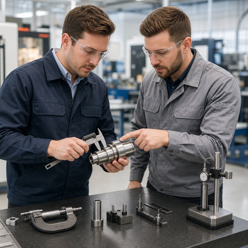
Why Burrs Form During Metal Cutting and Drilling
Shear Deformation and Plastic Flow at the Cutting Edge
Metal cutting burrs form primarily when material deforms plastically rather than shearing cleanly. As the tool engages, ductile metals—such as aluminum and mild steel—undergo lateral displacement instead of immediate separation, producing rollover burrs in sheet metal operations. Dull tools or improper feed rates exacerbate this: residual material folds over edges or fractures unevenly, generating tear burrs that require secondary deburring. Material hardness must strike a balance—overly soft alloys flow uncontrollably, while extremely hard metals resist deformation but fracture unpredictably. Optimized tool geometry mitigates this: sharp cutting edges and narrow tool angles reduce lateral force vectors. For instance, brass machining studies show that reducing cutting angles lowers burr formation by 40% compared to conventional broad-edge tools.
Thermal Effects and Recast Layers in High-Speed Operations
High-speed drilling intensifies frictional heat, softening material adjacent to the cutting zone. This localized thermal softening promotes excessive plastic deformation—especially at drill exit points—making it particularly problematic when machining titanium alloys, which have low thermal conductivity. Uncontrolled heat leads to recast layers: semi-molten metal re-solidifies into hardened dross that demands post-processing via abrasives or electrochemical methods. Cooling lubricants are not optional; ASME research shows mist coolant reduces exit burr height in stainless steel drilling by 68% versus dry machining. Operators must balance productivity with thermal thresholds—excessive spindle speeds can push surface temperatures above 800°C in ferrous metals, converting transient thermal effects into permanent microstructural defects that impair fatigue strength.
Optimizing Tools and Geometry for Burr-Free Metal Cutting
Sharp Edges, Positive Rake Angles, and Helix Optimization
Mirror-finished, honed cutting edges penetrate cleanly, promoting efficient shearing over tearing. A positive rake angle reduces cutting forces by directing chip flow upward and away from the workpiece. Helix angles should be tailored: steeper for softer alloys (e.g., aluminum), shallower for ferrous metals—ensuring consistent tooth engagement and preventing chip jamming. Together, these geometries cut material before significant plastic deformation occurs, substantially reducing exit-edge rollover and tear-off burrs.
Drill Point Design: Split Points vs. Conventional Tips for Metal Cutting Burrs Suppression
Split-point drills outperform conventional tips through self-centering action and reduced thrust force. Their 135° chisel edge geometry minimizes material displacement at hole exit, effectively suppressing crown burrs in non-ferrous materials like aluminum and brass. In AISI 304 stainless steel testing, split points achieved an 82% reduction in exit burr height versus 118° conventional drills—attributable to lower axial load and symmetrical cutting action.
Controlling Process Parameters to Minimize Metal Cutting Burrs
Feed Rate, Speed, and Depth of Cut Trade-Offs (AISI 304 & 6061-T6 Data)
Balancing feed rate, rotational speed (RPM), and depth of cut is critical to controlling burr formation. Each parameter directly affects shear stress mechanics at the tool–material interface. Research on AISI 304 stainless steel and 6061-T6 aluminum reveals distinct behavioral patterns:
For AISI 304:
Higher feed rates improve efficiency but concentrate shear deformation at tool exit points. When combined with insufficient speeds (<80 m/min)—even under coolant-rich conditions—this encourages lateral material flow and exit burrs exceeding 0.3 mm in 40% of cases. Conversely, very low feed rates (<0.15 mm/rev) reduce shearing forces but extend tool–material contact time, thermally hardening near-surface layers and increasing recast risk.
For 6061-T6 aluminum:
Speeds above 300 m/min produce thinner chips and significantly reduce entrance burr size due to efficient material separation. However, without rigid clamping, such speeds amplify workpiece vibration. Deeper cuts (>1.5× tool diameter) demand lower feed rates (<0.12 mm/rev) to prevent chip overload and side-burring along groove edges.
| Material | High Speed Effect | High Feed Rate Risk |
|---|---|---|
| AISI 304 | Heat-tinted recast layers | Severe exit burrs (>0.3 mm) |
| 6061-T6 Aluminum | Reduced entrance burrs | Groove-edge tearing defects |
Field validation confirms that optimized Holder-Muller Dynamic Stability (HMDS) enables deeper passes while maintaining chatter-free operation—even at 25% reduced feed rates. Precise chip load management—via digital feedscrews and enhanced machine rigidity—reduces observed burring incidents by 70% in AISI 304 drilling. For titanium alloys, where feed adjustments follow nonlinear trends, real-time acoustic emission monitoring provides effective error correction.
Supportive Fixturing and Edge Preparation Techniques
Backing Plates, Exit-Side Chamfers, and Clamping Strategies
Proper workpiece support and strategic edge preparation significantly reduce burrs generated during machining. Three proven techniques ensure cleaner exits:
- Backing plates provide rigid support behind thin materials, preventing deflection-induced tear-out burrs
- Exit-side chamfers act as guiding grooves for drill or bit emergence, enabling controlled chip evacuation
- Distributed clamping force minimizes vibration-induced irregularities, stabilizing tool engagement
Integrating these methods has reduced secondary deburring operations by up to 65% while improving dimensional accuracy—especially in sheet metal and extruded profile applications.
FAQ
What are metal cutting burrs?
Metal cutting burrs are rough edges or protrusions that form on materials during machining or drilling due to forces like plastic deformation, improper cutting conditions, and thermal effects.
How can burr formation be minimized?
Burr formation can be minimized by using sharp tools, optimizing cutting angles, applying cooling lubricants, and controlling feed rates and rotational speeds.
What role do thermal effects play in burr formation?
Thermal effects soften the material during high-speed operations, increasing plastic deformation and recast layers, which amplify burr formation, especially with materials like titanium alloys.
Why are split-point drills better for burr suppression?
Split-point drills reduce thrust force and material displacement due to their self-centering action and 135° chisel edge geometry, leading to fewer exit burrs.
What role do fixtures play in reducing burr formation?
Proper supportive fixturing, such as using backing plates, exit-side chamfers, and distributed clamping, minimizes vibration and material deformation, significantly reducing burr formation.