 Small batches, high standards. Our rapid prototyping service makes validation faster and easier —
  EN
EN

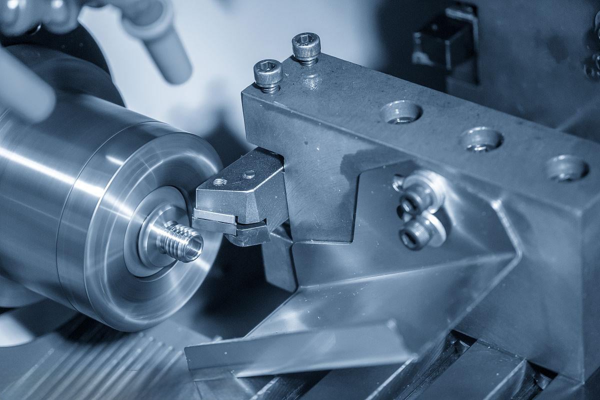
The Physical Limits of Sharp Corners in CNC Machining
Designers often treat internal corners as an afterthought, but in sharp corners manufacturing, the rotating cutting tool immediately imposes a physical limit no shop can bypass. Unlike external edges—which can appear sharp because material is removed from multiple sides—internal corners always inherit the circular profile of the end mill. Understanding this fundamental restriction is the first step toward manufacturable designs and predictable lead times.
Tool Geometry and End Mill Diameter Dictate Minimum Internal Radii
The radius left in any internal pocket or cavity is simply the radius of the cutting tool. A standard cylindrical end mill cannot produce a true 90‑degree internal corner because its spinning motion always leaves a rounded fillet equal to half its diameter. This is not a machine precision issue—it is basic geometry. To reduce the corner radius, shops must switch to progressively smaller tools: a 2 mm corner requires an end mill no larger than 4 mm in diameter, a 1 mm corner demands a 2 mm tool, and an 0.5 mm corner forces the use of fragile 1 mm cutters. Each step to a smaller diameter dramatically lowers material removal rates and raises the risk of tool deflection, chatter marks, and catastrophic breakage. In practice, a 3 mm or larger radius is far more economical for bulk material removal, while ultratight radii below 0.5 mm can more than double machining time and scrap cost. For designers, the takeaway is clear: the minimum achievable internal radius is defined by the smallest tool that can still efficiently machine the entire pocket—not by an arbitrary specification on the drawing.
GD&T 'Sharp Corner' vs. Machinist Reality: Bridging the Specification Gap
When a drawing calls out a sharp internal corner without a radius under GD&T, a machinist does not interpret it as a request for a mathematically perfect zero‑radius feature. Instead, the common interpretation—reinforced by ASME Y14.5—is that the corner must be “sharp” in the sense of lacking a deliberately specified fillet, but a residual radius from the manufacturing process is expected and allowed. The problem arises when functional demands truly require a near‑zero radius, yet the specification remains ambiguous. This mismatch leads to returned parts, reworks, and lengthy back‑and‑forth between engineering and production. External corners can achieve a visibly sharp finish because the cutter can sweep from both intersecting faces, but internal corners are always bound by the tool’s diameter. To bridge the gap, a clear note such as “MAX R0.2 mm” or a callout for an allowable relief (e.g., a dog‑bone slot) must replace the generic “sharp” notation. Explicitly stating a maximum radius reduces programming and inspection ambiguity, avoids over‑specification, and aligns design intent with the physical reality of CNC machining.
Design-for-Manufacturability Solutions for Sharp Corner Requirements
To overcome the inherent constraints of sharp corners manufacturing, engineers can adopt proven design-for-manufacturability (DFM) strategies that preserve functional intent while enabling economical production. The two most effective paths are substituting internal sharp features with standard machinable alternatives or specifying a small, practical radius that does not compromise performance.
Standard Fillet Alternatives: T-Bone, Dog-Bone, and Corner-Relief Strategies
When a mating component requires an apparent right‑angle interface, simple fillets may not suffice. Three widely used techniques solve this without imposing impossible tool demands:
- T‑bone milling creates an undercut slot behind the internal corner, providing clearance so a square block can seat flush against two walls.
- Dog‑bone geometry adds enlarged semicircular reliefs at both ends of a slot; the straight mid‑section accommodates the mating part while the radii match the end mill’s natural shape.
-
Corner‑relief holes drilled precisely at the intersection point remove material ahead of milling, effectively turning a zero‑radius corner into a machinable pocket with a radius equal to the drill size.
All three methods rely on standard tooling and straightforward toolpaths, keeping programming complexity in check. In high‑volume production, these alternatives often reduce cycle time by eliminating the need for specialized slow‑speed operations. Engineering teams should verify that the chosen relief does not weaken the part below design limits; finite‑element simulation can confirm safety.
When to Specify a Practical Radius (e.g., 0.5 mm) Without Compromising Function
Many components that appear to demand sharp internal edges can in fact tolerate a small radius once functional requirements are carefully examined. Adding a radius as modest as 0.5 mm allows a shop to use a common end mill diameter, avoiding slower micro‑tools and extended run times. The key is to evaluate three factors:
- Assembly fit – Will a radius interfere with the intended mating surface? A small clearance pocket or a chamfer on the mating part often resolves interference.
- Stress distribution – A radius reduces stress concentration; in load‑bearing areas, a fillet may actually improve fatigue life.
-
Aesthetic and sealing concerns – Unless the corner forms part of a precision seal or a brand‑defining visual line, a 0.5 mm break edge is invisible to the naked eye.
Collaborating with the machining partner during the design phase helps determine the largest permissible radius that still satisfies all functional tests. This simple adjustment regularly cuts machining time by 15–25% and lowers reject rates, since measurable radii are far easier to inspect than an unverifiable “sharp corner.”
Cost and Lead Time Impacts of Unmanufacturable Sharp Corner Specifications
Insisting on impossible-to-machine sharp internal corners triggers a cascade of hidden expenses that extend far beyond the cutting tool. These demands disrupt programming logic, tighten setup tolerances, and fundamentally alter production economics.
20–35% Increase in Programming, Setup, and Toolpath Complexity
When a design calls for a zero-radius corner, CAM programmers cannot rely on standard tool paths. They must craft layered, multi-pass strategies using extremely small end mills, often with length-to-diameter ratios above 12:1. This forces slower feed rates, shallower depth cuts, and frequent tool changes to avoid breakage. A part that would machine in minutes with a practical radius can see programming and setup time swell by 20–35%, as shops must model complex clearance moves and add workholding for secondary operations. The combined effect inflates both machine burden and the hours billed for skilled operators who orchestrate these delicate processes.
Higher Inspection Burden and Reject Rates Due to Unverifiable Features
Verifying a sharp internal corner pushes standard quality control beyond its practical limits. Go/no‑go gauges become ineffective, forcing reliance on CMM (Coordinate Measuring Machine) systems, which dramatically slows throughput. Even then, the very nature of a true sharp corner makes it an unverifiable feature—there is always some radius left by the tool—so dimensional disputes arise. This ambiguity increases inspection time per part and drives up reject rates, as parts that technically meet function may be scrapped simply because the specification cannot be objectively confirmed.
Structural Integrity Risks of Unmodified Sharp Corners
A sharp internal corner is not merely a geometric feature; it is a stress concentration point that fundamentally alters how a component carries load. When an external force is applied, stress lines flow through the part. At a sharp corner, these lines are forced to make an abrupt directional change, crowding together at the root of the corner. This phenomenon creates a localized stress that is a multiple of the nominal stress in the surrounding material, a principle quantified by the stress concentration factor (Kt). For a theoretically sharp re-entrant corner, Kt approaches infinity—meaning even a low applied load can initiate a crack from a microscopic material flaw or machining mark at that exact point. A common misconception is that a finite element analysis (FEA) simulation with a sharp corner will show a worst-case safe result; in reality, mesh refinement at that singularity will show stress values climbing without convergence—a mathematical indication of a structurally unsound model. A comparative analysis underscores the danger:
| Design Specification | Manufactured Reality | Structural Consequence |
|---|---|---|
| Sharp internal corner | Micro-radius from end mill, surface discontinuities | Kt may remain >3, providing a dominant site for fatigue crack initiation |
The dominant failure mode in dynamically loaded components is fatigue, responsible for the vast majority of mechanical service failures. A crack initiated at a sharp corner will propagate incrementally under cyclic stress until the remaining cross-section can no longer support the peak load, leading to sudden fracture. This risk is not limited to fatigue; in brittle materials or under single overload events, the same stress concentration can cause immediate catastrophic failure in precision parts ranging from medical implants to aerospace brackets. Specifying an unmodified sharp corner, therefore, is not a conservative design approach—but an active choice to embed a predictable failure origin into a part, trading long-term reliability for a feature that is impossible to manufacture as drawn.
FAQ
Why can’t CNC machines create perfectly sharp internal corners?
The rotating cutting tools used in CNC machining naturally leave rounded corners due to their circular geometry. A true 90-degree sharp internal corner is geometrically impossible to achieve without additional design considerations or post-processing.
How does a designer specify sharp corners correctly?
Instead of ambiguous notations like "sharp corner," designers should add explicit notes like "MAX R0.2 mm." This ensures alignment between design intent and machining capabilities, reducing manufacturing errors and delays.
Why are small radii expensive to machine?
Smaller radii require tiny, fragile cutting tools with slower material removal rates. This increases machining time, setup complexity, and the risk of tool breakage, leading to higher costs.
What are T-bone and dog-bone strategies?
These are design modifications where additional material reliefs are created in corners. T-bone involves undercutting, while a dog-bone adds semicircular reliefs to facilitate easier machining and ensure proper fit for mating components.