 Small batches, high standards. Our rapid prototyping service makes validation faster and easier —
  EN
EN

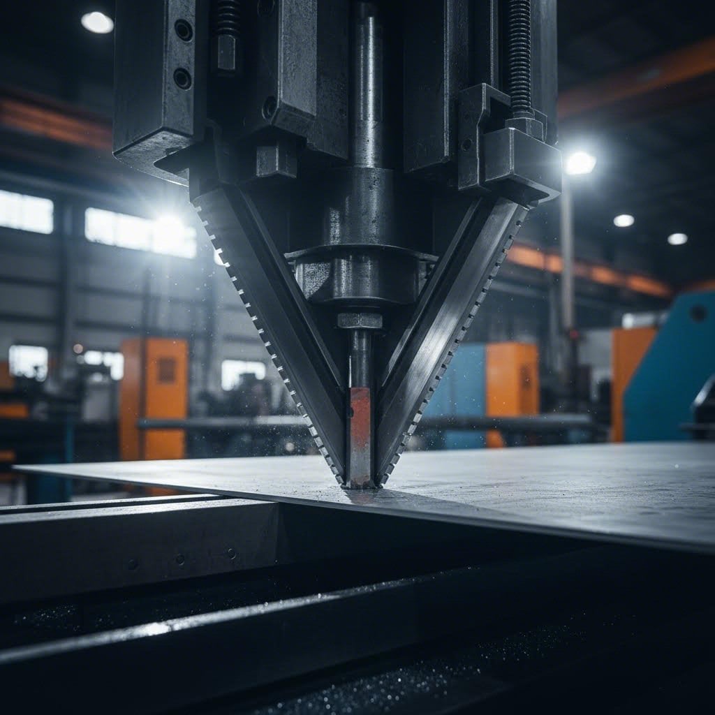
The Science of Bend Radius: Material Properties and Failure Mechanics
How material thickness and alloy type define minimum bend radius (e.g., 1×T for mild steel vs. 2×T for 6061-T6 aluminum)
The minimum bend radius is a fundamental mechanical threshold—not an arbitrary design preference—determined by the interaction of material thickness and alloy-specific properties. Thickness amplifies strain at the outer fiber during bending; doubling gauge typically requires a proportionally larger radius to avoid cracking.
Alloy type governs this relationship decisively. Mild steel’s balanced ductility and moderate tensile strength allow a minimum bend radius of approximately 1×T, where the inside radius equals material thickness. In contrast, 6061-T6 aluminum—strengthened by precipitation hardening—exhibits reduced elongation after tempering, necessitating a more conservative 2×T or greater minimum radius to prevent outer-surface cracking. This divergence underscores why generic radius rules fail without alloy-specific verification: material selection constrains geometry as rigorously as it defines performance.
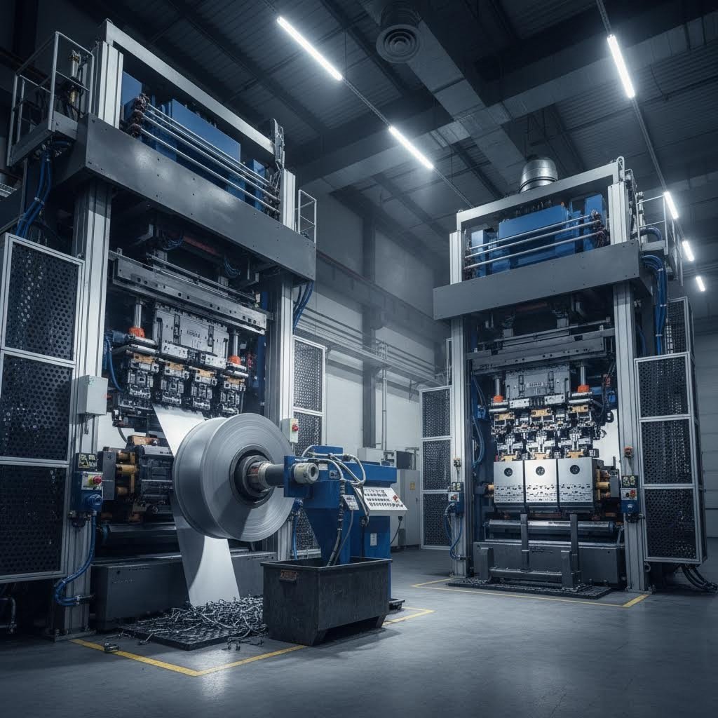
Ductility’s role: Why stainless steel demands larger bend radius than aluminum despite comparable thickness
Ductility—the capacity for plastic deformation before rupture—is the dominant factor in bend radius requirements, often overriding assumptions based on hardness or perceived formability. Austenitic stainless steels like 304 exemplify this: despite similar thickness and tensile strength to many aluminum alloys, they require significantly larger radii (typically ≥2×T) due to pronounced strain hardening. As bending progresses, localized yield strength rises sharply, concentrating strain into a narrow zone and accelerating micro-void coalescence.
By comparison, aluminum alloys such as 5052-H32 display more uniform elongation behavior, distributing strain broadly without abrupt hardening spikes. This allows certain aluminum grades to tolerate near-1×T radii—highlighting that ductility, not strength alone, dictates formability. For structural housings or tightly packaged assemblies, overlooking this distinction risks tooling mismatch, prototype failure, and costly redesign cycles.
Cracking at the outer fiber: Stress concentration, grain orientation, and a real-world aerospace bracket failure
Bend-induced cracking initiates predictably at the outer fiber—the location of peak tensile stress and maximum elongation. Its severity depends on both macro-scale radius selection and microstructural features, especially grain orientation. In cold-rolled sheet, grains align parallel to the rolling direction; bending along this axis offers fewer barriers to crack propagation, while transverse bending forces fractures across multiple grain boundaries, enhancing resistance.
A documented aerospace bracket failure illustrates the consequences. A 2024-T3 aluminum part designed with a marginally compliant 1.5×T radius fractured during cyclic loading testing. Metallurgical analysis revealed intergranular cracking along the outer fiber—directly linked to longitudinal grain flow and insufficient radius-induced stress concentration. Redesigning the radius to 2.5×T and rotating the grain orientation to transverse eliminated the failure mode. This case confirms that published minimum bend radii represent statistical fracture thresholds—not safe operating limits—particularly under fatigue loading or when grain direction and manufacturing tolerances compound risk.
Bend Radius and Manufacturing Feasibility: Tooling, Scrap, and Cost
Standard tooling limitations: Punch nose radii (0.010″–0.250″) and die width constraints shaping practical bend radius selection
Achievable bend radius is dictated less by design intent than by standard press brake tooling. Common punch nose radii range from 0.010″ to 0.250″, while V-die openings are typically set to eight times material thickness, collectively defining the resulting inside radius. Designs specifying radii outside this standard range force custom tooling—coining setups or dedicated dies—shifting jobs from routine production to specialty fabrication with higher lead times and costs. The most robust and repeatable process aligns the bend radius closely with material thickness, leveraging off-the-shelf tooling and proven setup parameters.
Cost impact of aggressive bend radius: Increased setup time, scrap rates, and need for secondary operations like annealing or grinding
Aggressive bend radii drive cost multipliers—not just per-part labor but systemic inefficiencies. Industry data shows tight-radius forming can increase fabrication costs by 20–40%, primarily from specialized tooling, slower cycle times, and heightened operator oversight. Scrap rates rise proportionally: fracture risk at the outer fiber climbs significantly, increasing scrap by up to 1.5× normal labor cost per part. When material limits are exceeded, secondary operations become unavoidable—annealing to restore ductility, or grinding to remove surface defects that act as crack nucleation sites. These steps add energy, time, and process complexity, reinforcing why standard radii deliver the strongest balance of precision, repeatability, and cost control.
Precision and Performance Trade-Offs: Springback, Tolerances, and Structural Integrity
Springback behavior: Empirical angular deviation (±0.3°–1.2°) linked to bend radius reduction in 304 stainless steel
Springback—the elastic recovery after bending force release—increases nonlinearly as bend radius decreases. In 304 stainless steel, angular deviations of ±0.3° to ±1.2° are routinely observed near minimum radius limits. A comprehensive study confirmed that reducing radius from 2×T to 1×T can amplify springback by nearly 400%, depending on gauge and temper. This variability undermines dimensional control: a nominal 90° bend may land between 88.8° and 91.2°, disrupting fit in modular assemblies and demanding iterative over-bending compensation. Where ±0.5° angle tolerance is critical—for welding fixtures or interface alignment—a slightly larger, more predictable radius becomes a functional necessity, not a compromise.
Strength degradation below minimum bend radius: FEA evidence showing up to 22% tensile strength loss in cold-rolled steel
Forming below the minimum bend radius induces subsurface damage invisible to inspection but quantifiably detrimental to performance. Finite Element Analysis (FEA) of cold-rolled steel reveals micro-void formation and grain distortion along the outer tensile fiber—even without visible cracking—reducing ultimate tensile strength in the bent zone by up to 22% versus parent material. This degradation invalidates structural calculations: a bracket designed with a safety margin assumes full material strength, yet its weakest point may carry only 78% of expected load capacity. Under cyclic loading, these micro-defects evolve into fatigue cracks, shortening service life. Adhering to the minimum bend radius is therefore essential—not as a guideline, but as the boundary where predicted mechanical performance remains valid.
Bend Radius Standards vs. Real-World Application Gaps
Industry-standard charts present minimum bend radii as clean multiples of thickness—e.g., 1×T for mild steel, 2×T for 6061-T6 aluminum—but these values assume idealized, laboratory-grade conditions. In practice, modern air bending dominates production, and the final inside radius is governed primarily by die opening width, not punch nose radius. A designer’s CAD model specifying a 0.030″ radius may produce a part with a 0.125″ radius due to standard die selection—causing flat-pattern miscalculations and out-of-tolerance components.
Further erosion comes from batch-to-batch variation: material hardness, surface condition, and grain direction shift across coils, meaning a radius validated on one prototype may crack during full production. To bridge this gap, experienced fabricators apply a practical safety margin—designing radii at least 50% larger than the metallurgical minimum. They also respect physical tooling constraints: standard punch noses are discrete increments (0.010″, 0.030″, 0.062″, etc.), and forcing non-standard sizes triggers custom grinding, extended setup, and higher NRE costs.
Real-world application demands trade-offs beyond metallurgy. A theoretically sound radius may conflict with assembly interference, exceed achievable angle tolerance (±1° is typical in uncontrolled environments), or necessitate stress-relieving annealing—introducing cost, delay, and quality risk. Whether forming a high-load spring-steel clip or a cosmetic sharp corner free of orange-peel texture, the standard chart serves only as a starting point. Reliable outcomes depend on collaborative validation between design and manufacturing—testing actual material, tooling, and process parameters before committing to production.
FAQ
Q1: What is the significance of minimum bend radius in metal fabrication?
A1: The minimum bend radius ensures material integrity during bending by preventing cracking, especially at the outer fiber. It is a function of material thickness and alloy type, directly affecting mechanical performance.
Q2: Why do different materials require varying bend radii?
A2: Material ductility and alloy-specific properties such as strain hardening play a significant role. For instance, mild steel with balanced ductility can handle tighter bends (e.g., 1×T), whereas tempered alloys like 6061-T6 aluminum need larger radii (e.g., 2×T or greater) to avoid cracking.
Q3: How does grain orientation influence bend performance?
A3: Grain orientation affects crack resistance during bending. Bending along the rolling direction reduces resistance, while transverse bending minimizes crack propagation by crossing multiple grain boundaries.
Q4: What are the cost implications of aggressive bend radii?
A4: Tight bends increase costs through higher tooling expenses, slower production cycles, additional scrap, and potential secondary operations like annealing or grinding to repair defects.
Q5: What is springback, and why does it matter?
A5: Springback refers to the elastic recovery of material after bending. It leads to angular deviations that disrupt dimensional accuracy, particularly in tighter bends, requiring iterative compensations or adjustments in tooling setups.
Table of Contents
-
The Science of Bend Radius: Material Properties and Failure Mechanics
- How material thickness and alloy type define minimum bend radius (e.g., 1×T for mild steel vs. 2×T for 6061-T6 aluminum)
- Ductility’s role: Why stainless steel demands larger bend radius than aluminum despite comparable thickness
- Cracking at the outer fiber: Stress concentration, grain orientation, and a real-world aerospace bracket failure
- Bend Radius and Manufacturing Feasibility: Tooling, Scrap, and Cost
- Precision and Performance Trade-Offs: Springback, Tolerances, and Structural Integrity
- Bend Radius Standards vs. Real-World Application Gaps
- FAQ