 Small batches, high standards. Our rapid prototyping service makes validation faster and easier —
  EN
EN

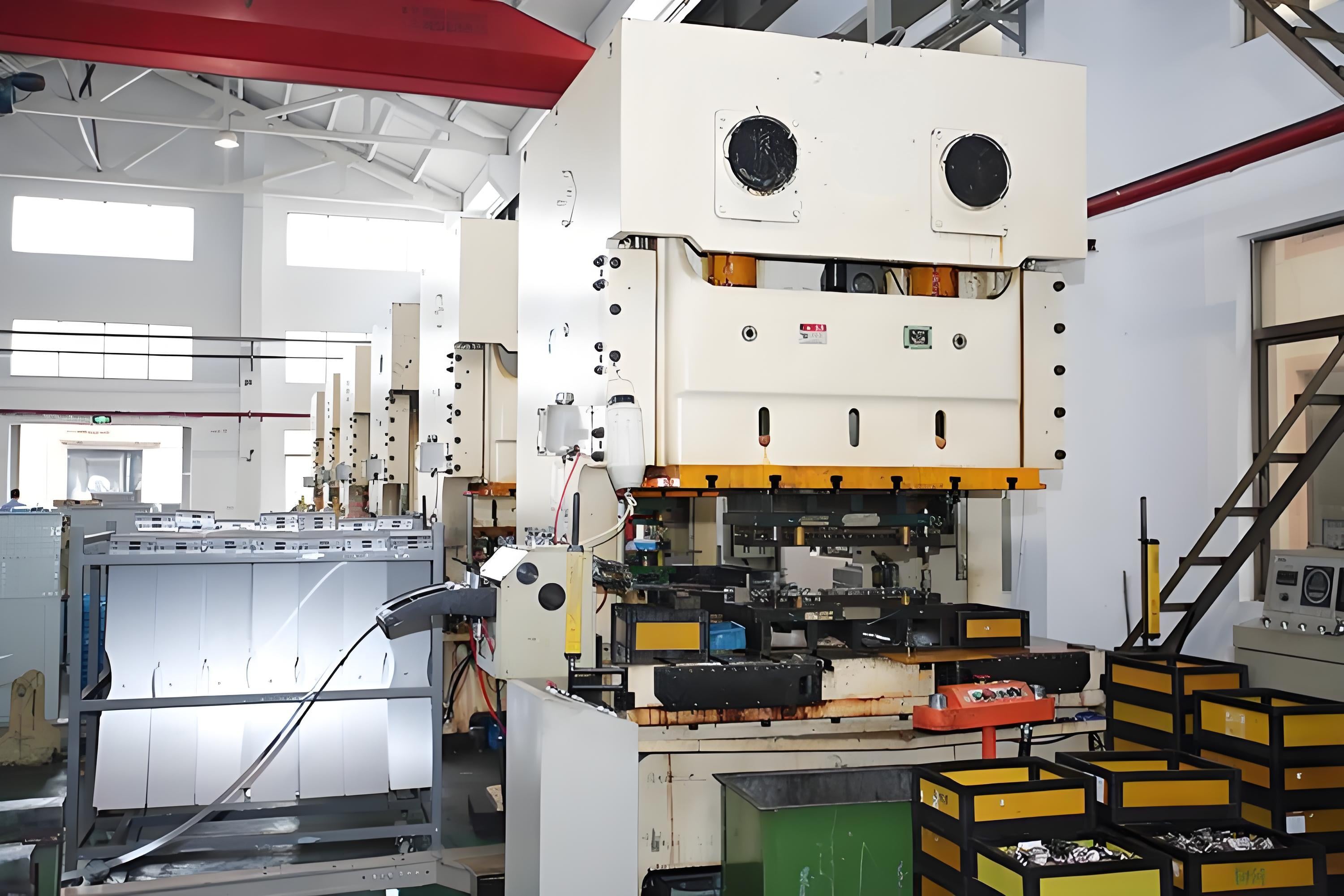
Thermal Effects: The Leading Cause of Dimensional Drift in Production
Thermal expansion of machine tools and workpieces during extended cycles
Heat from spindle rotation, cutting friction, and motor operation is the dominant contributor to dimensional drift in precision manufacturing. As production cycles extend, cast-iron machine structures absorb and retain heat—causing axial spindle elongation, bed distortion, and tool center point displacement. These thermal deformations account for up to 70% of geometric errors in high-precision CNC systems (ISO 230-3:2016), directly compromising part consistency. Workpieces—especially aluminum and titanium—exhibit significant localized expansion or contraction under cutting heat, adding another layer of variability. Without thermal compensation or controlled warm-up protocols, accuracy degrades progressively across a run. Even servo drives contribute incremental heat over time, reinforcing drift across batches. Thermal growth of both machine structure and workpiece material remains the single largest controllable source of dimensional drift in production engineering.
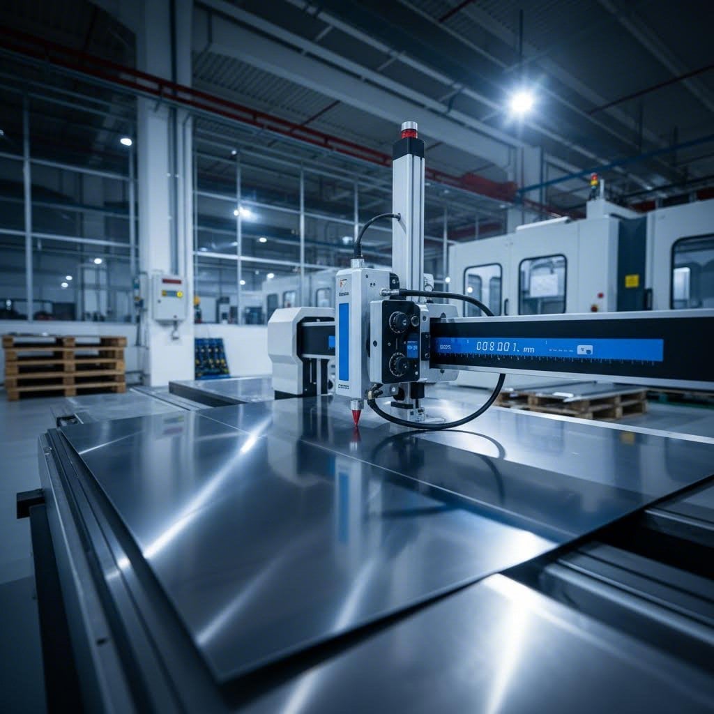
Ambient temperature and humidity fluctuations undermining dimensional stability
Ambient conditions introduce a secondary—but critical—layer of instability. A ±1 °C shift in shop-floor temperature induces measurable deviations in tool path geometry and final dimensions due to proportional expansion or contraction of scales, guideways, and structural components. Uncontrolled overnight cooling or daytime solar heating creates batch-to-batch inconsistency that mimics tool wear. Humidity compounds this: high moisture levels can swell hygroscopic or composite materials, degrade pneumatic response, and cause condensation on sensors—leading to signal noise, corrosion, and accelerated oxidation of guideways. Stable environmental control is therefore not optional but foundational: it prevents ambient fluctuations from amplifying the machine’s intrinsic thermal behavior and ensures repeatability across shifts and seasons.
Mechanical Degradation: Equipment Wear Driving Cumulative Dimensional Drift
Tooling, die, and bearing wear introducing positional and force variability
Mechanical wear in cutting tools, forming dies, and spindle bearings progressively erodes process precision. Flank wear alters tool geometry, increasing cutting forces and deflecting the workpiece; crater wear weakens the edge and introduces force variability. A worn tool can shift the effective cutting point by 10–30 µm after just 500 cycles (CIRP Annals, 2022). Similarly, die wear in stamping or forging changes cavity geometry and material flow, causing dimensional shifts up to 0.2% of original tolerance. Bearing clearance growth—driven by fatigue and adhesive wear—introduces radial and axial play, resulting in spindle runout of 5–15 µm. The table below summarizes key wear mechanisms and their dimensional impact:
| Wear Type | Description | Impact on Dimensional Drift |
|---|---|---|
| Flank Wear | Gradual abrasion of tool flank surface | Shifts tool center, leading to undersized or oversized features |
| Crater Wear | Depression on tool face from diffusion | Weakens edge, increases cutting force variability |
| Bearing Clearance | Enlargement of rolling-element gaps | Introduces random spindle runout of 5–15 µm |
| Die Adhesive Wear | Material transfer and galling on die surfaces | Alters cavity geometry, causing inconsistent part dimensions |
These wear-driven changes in position and force translate directly into cumulative dimensional drift—particularly in unmonitored, long-run production.
Guideway erosion and servo system drift compounding error over time
Linear guideways and ball screws degrade gradually under repeated load, increasing backlash, stick-slip, and lost motion. Research shows that 0.02 mm of guideway wear can produce 0.05 mm of dimensional drift in finished parts over 10,000 cycles (Precision Engineering Journal, 2023). Concurrently, servo systems drift as encoders accumulate contamination, amplifiers experience thermal drift, and bearing friction changes—causing commanded positions to diverge from actual motion. Aggressive loop compensation may mask underlying error through overshoot or oscillation, yielding parts that drift subtly but steadily out of tolerance. Critically, this compounding effect means dimensional drift can exceed limits even when tools remain within wear specifications. Regular geometric calibration and servo loop tuning are essential to isolate and correct these interdependent error sources.
Material-Induced Instability: Residual Stress and Variability in Dimensional Drift
Springback, welding distortion, and machining-induced residual stress release
Residual stress is a root cause of many dimensional drift issues. Bending, welding, and machining lock non-uniform internal stresses into parts—triggering delayed deformation. Springback causes bent sheet metal to partially revert post-forming, introducing persistent offsets. Welding distortion arises from intense, localized heating and uneven cooling, generating tensile and compressive zones that may relax slowly under thermal cycling or mechanical loading. Machining further destabilizes equilibrium: removing material from a stressed blank triggers stress relaxation, often warping thin-walled components unpredictably. In high-volume production, such distortions accumulate—resulting in out-of-spec parts and unplanned rework. Mitigation strategies—including stress-relief annealing, optimized cut sequencing, and fixturing that accommodates relaxation—must be integrated early in process design.
Inherent material variation (e.g., grain structure, yield strength) amplifying drift
Material heterogeneity significantly amplifies dimensional drift. Grain size, orientation, and distribution vary between batches—and even within a single billet—altering yield strength and elastic modulus. These microstructural differences change how a part deforms under clamping or forming loads: coarser grains may lower yield strength, increasing plastic deformation under identical pressure; variations in elastic modulus affect springback magnitude and direction. Over successive cycles, such subtle shifts accumulate, causing the process mean to drift. While full material homogeneity is unattainable, consistent supplier qualification, incoming material testing (e.g., tensile sampling per ASTM E8), and statistical process control of key properties help constrain this source of variability.
Process Control Failures: Lubrication, Clamping, and Parameter Drift Accelerating Dimensional Drift
Inconsistent process controls are a primary accelerator of dimensional drift. Lubrication failure—whether from insufficient volume, degraded fluid, or mismatched viscosity—increases friction and localized heating, inducing thermal expansion in slides, spindles, and workpieces. Improper clamping force compounds the issue: excessive pressure permanently deforms thin-walled parts, while insufficient force permits movement during machining—both introducing systematic offsets. Cutting parameters—speed, feed, and depth—also drift over time due to controller aging, operator adjustments, or sensor drift, pushing the process away from its validated state. Without real-time monitoring and closed-loop correction, these small deviations compound across cycles. Addressing them requires disciplined preventive maintenance, adaptive fixturing, and parameter stabilization protocols—such as automated feed-forward compensation and periodic validation against master artifacts—to sustain repeatable, tolerance-compliant output.
FAQ
What are the main causes of dimensional drift in production?
Dimensional drift is primarily caused by thermal effects, mechanical degradation, material-induced instability, and failures in process control. Factors such as thermal expansion, equipment wear, residual stresses, and improper lubrication or clamping can contribute to variability in manufacturing precision.
How does thermal expansion affect CNC precision?
Thermal expansion due to heat from spindle rotation, cutting, and motor operation causes machine components to deform, directly compromising part consistency. A rise in shop-floor temperature can also alter geometry and material dimensions, affecting accuracy.
What role does mechanical wear play in dimensional drift?
Mechanical wear in tools, dies, bearings, and guideways leads to positional errors, force variability, and cumulative buildup of geometric inconsistencies. It is essential to monitor and mitigate wear through preventive maintenance and calibration.
Can residual stress cause dimensional drift in parts?
Yes, residual stress induced by bending, welding, and machining can distort parts over time. Stress relief techniques like annealing and proper design can minimize these effects.
How does ambient temperature and humidity affect manufacturing accuracy?
Ambient fluctuations can expand or contract machine components and materials, degrading accuracy. Stable environmental controls help prevent these inconsistencies.
What are the best strategies for minimizing dimensional drift?
Key strategies include thermal compensation, regular calibration, stress-relief treatments, proper material testing, precise process controls, and maintaining stable environmental conditions.
Table of Contents
- Thermal Effects: The Leading Cause of Dimensional Drift in Production
- Mechanical Degradation: Equipment Wear Driving Cumulative Dimensional Drift
- Material-Induced Instability: Residual Stress and Variability in Dimensional Drift
- Process Control Failures: Lubrication, Clamping, and Parameter Drift Accelerating Dimensional Drift
- FAQ