 Small batches, high standards. Our rapid prototyping service makes validation faster and easier —
  EN
EN

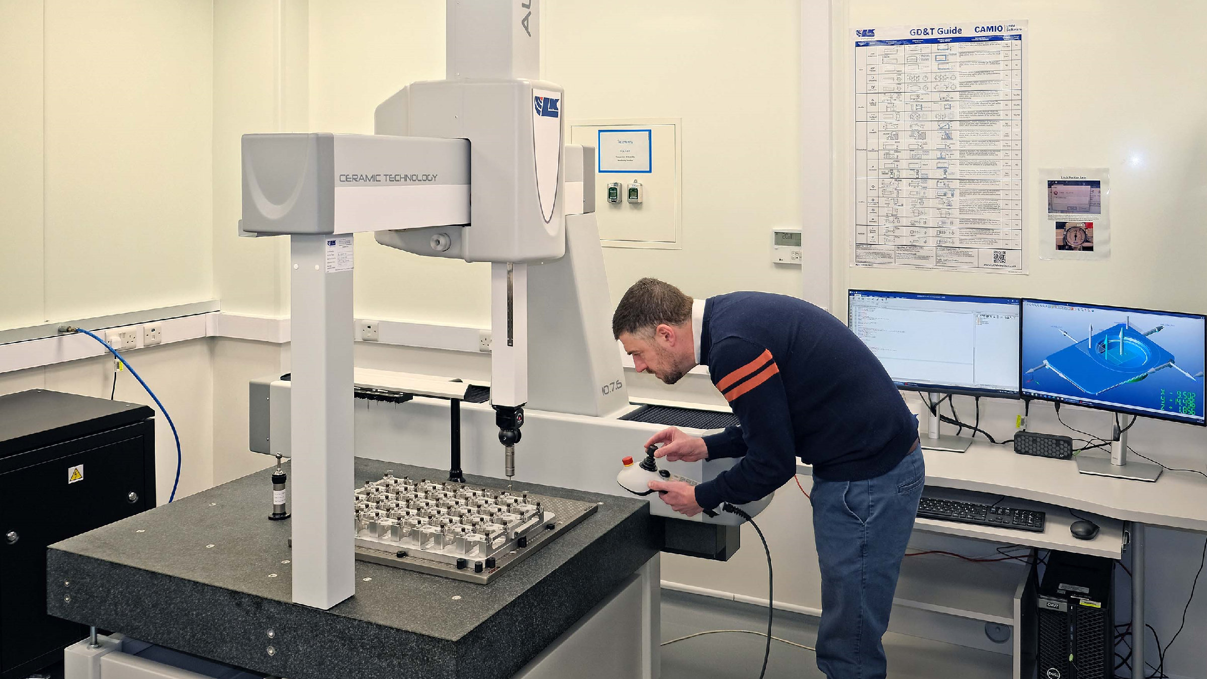
Material Properties Governing Metal Parts Fit
The final fit of mated metal parts depends heavily on intrinsic material characteristics. Two critical categories—thermal behavior and mechanical response under load—dictate how components interact during assembly and throughout service life.
Thermal Expansion and Contraction in Assembly and Service
Thermal expansion is a primary driver of dimensional change. Metals expand when heated and contract when cooled, with rates quantified by the coefficient of thermal expansion (CTE). For example, aluminum (CTE ~23 µm/m-°C) expands nearly twice as much as steel (CTE ~12 µm/m-°C) for the same temperature rise. In mixed-material assemblies, a 100°C increase can reduce an interference fit by over 0.1 mm per meter of diameter—potentially converting a tight press fit into a loose clearance.
These effects matter both during assembly and operation. Heat-assisted fitting—such as heating a hub to slide onto a shaft—leverages thermal expansion to ease installation, but the joint must be engineered so that subsequent contraction delivers the target interference. Conversely, in-service thermal cycling—as seen in engine blocks or exhaust manifolds—can cyclically loosen fasteners or induce fretting wear. Selecting materials with closely matched CTEs or incorporating robust design margins helps sustain fit reliability over the part’s lifetime.
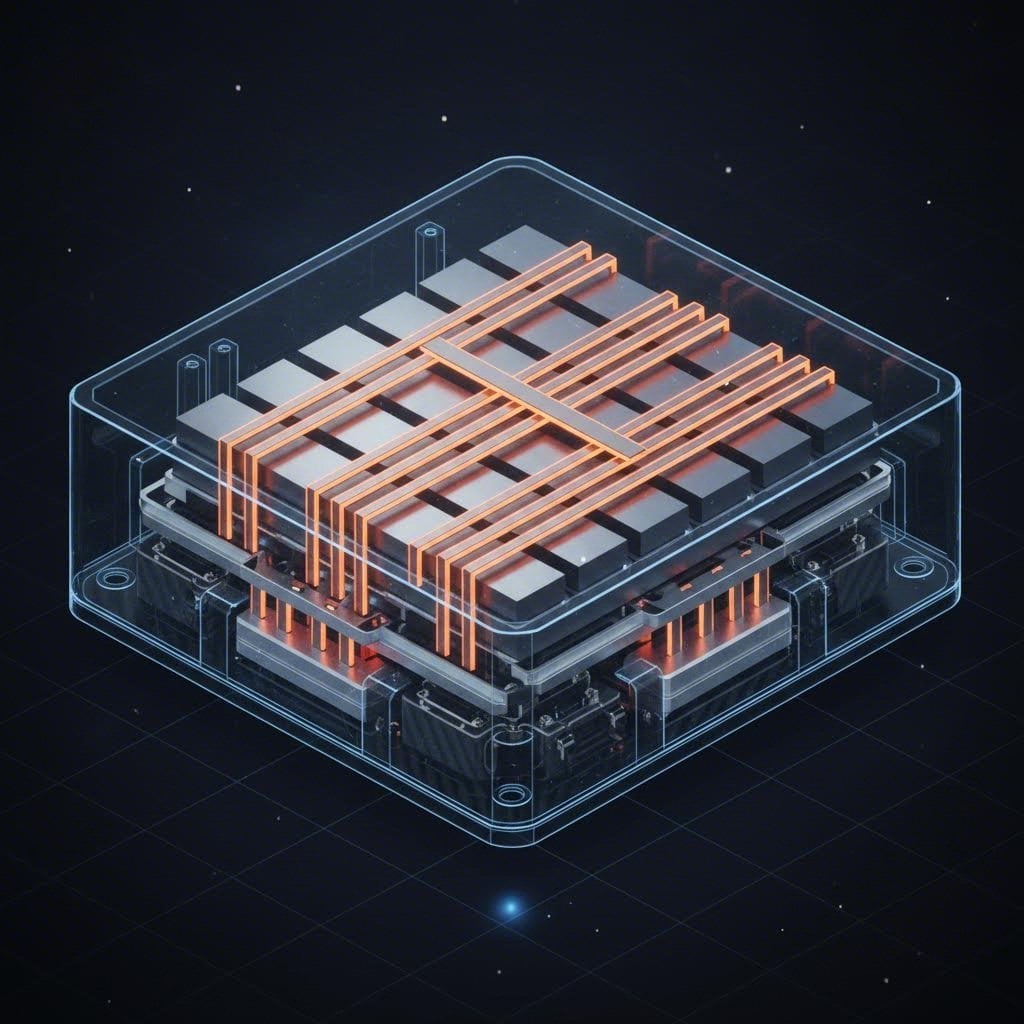
Elasticity, Yield Strength, and Hardness Under Load
Beyond thermal effects, a metal’s mechanical response to stress shapes the final fit. Elasticity enables temporary deformation followed by recovery; in a press-fit, both shaft and hub deform elastically, generating contact pressure that secures the joint. Exceeding yield strength during assembly causes permanent distortion—altering intended interference and compromising function.
Yield strength defines the stress threshold at which plastic deformation begins. A low-yield-strength shaft pressed into a hard hub may neck down permanently, reducing grip. Hardness—resistance to surface indentation—affects galling and abrasion during forced insertion. A harder pin in a softer bore can scrape material away, diminishing effective interference; matching hardnesses typically yields more stable, repeatable fits. Designers therefore balance high elasticity with adequate yield strength to ensure secure, damage-free assembly—and select appropriate hardness combinations to minimize wear in dynamic applications like gear splines and bearing seats.
Manufacturing Precision and Tolerancing for Reliable Metal Parts Fit
Hole/Shaft Fit Systems and Dimensional Tolerance Selection
Selecting the correct hole/shaft fit system—clearance, transition, or interference—directly determines functional performance. Dimensional tolerances, defined per international standards such as ISO 286, establish allowable deviation from nominal size while balancing manufacturability and reliability. For rotating shafts in bearings, an H7/g6 clearance fit ensures smooth, lubricated motion without binding. Press-fit assemblies requiring torque transmission often specify tighter interference fits like H7/p6—eliminating the need for additional fasteners.
Tolerance grade selection depends on part function, material, and production method: precision grinding achieves IT5–IT6, whereas general turning typically delivers IT8–IT9. Over-specifying tight tolerances increases cost disproportionately—industry estimates indicate that halving the tolerance band can double machining expenses. The objective is pragmatic: assign fits and tolerances that guarantee intended metal parts fit across all operational conditions—not just at room temperature or under ideal lab conditions.
Tolerance Stack-Up and Its Impact on Actual Interface Fit
Even when each component meets its individual tolerance, accumulated deviations across multiple features—known as tolerance stack-up—can shift final interface fit outside functional limits. Worst-case summation assumes all parts deviate maximally in the same direction, while root-sum-square (RSS) analysis applies statistical probability for higher-volume production. As shown below, increasing part count sharply tightens required individual tolerances:
| Assembly Tolerance Requirement | Individual Part Tolerance (3 parts) | Individual Part Tolerance (5 parts) | Manufacturing Difficulty |
|---|---|---|---|
| ±0.1 mm (±0.004 in) | ±0.03 mm (±0.001 in) | ±0.02 mm (±0.0008 in) | High precision required |
| ±0.2 mm (±0.008 in) | ±0.07 mm (±0.003 in) | ±0.04 mm (±0.0016 in) | Standard precision |
| ±0.5 mm (±0.020 in) | ±0.17 mm (±0.007 in) | ±0.10 mm (±0.004 in) | Easily achievable |
Early CAD-based tolerance analysis allows engineers to allocate tighter tolerances only where functionally necessary—avoiding costly over-control on non-critical features and ensuring final metal parts fit remains within specification without rework.
Operational and Environmental Factors That Alter Metal Parts Fit
Load, Torque, and Thermal Cycling Effects on Interference and Clearance Fits
Real-world loading conditions frequently challenge the designed metal parts fit—diverging significantly from static blueprint assumptions. Applied load and torque can cause elastic or plastic deformation, altering interface geometry. Excessive torque on threaded fasteners, for instance, may yield the material, converting a planned clearance fit into unintended interference—or collapsing preload entirely. Improper torque application contributes to over 25% of mechanical joint failures, according to industry maintenance data.
Thermal cycling introduces another layer of complexity. Dissimilar materials expand and contract at different rates: a steel shaft in an aluminum housing may lose interference at elevated temperatures due to aluminum’s higher CTE, risking spin-out. Conversely, rapid cooling can cause seizure in precision clearance fits if the inner component contracts slower than its housing. Accounting for full operational temperature range—not just ambient—is therefore essential to maintaining assembly integrity across the service life.
Surface Conditions and Assembly Practices Influencing Effective Metal Parts Fit
Surface Finish, Lubrication, and Contamination in Real-World Fit Performance
Achieving the intended metal parts fit requires strict control of surface conditions. Surface roughness directly influences effective interference: peak asperities crush during press-fit assembly, potentially reducing preload by up to 30%. Proper lubrication lowers insertion force and prevents galling—especially critical with stainless steels and other work-hardening alloys. Contaminants—including metal chips, dust, or excess lubricant—can lodge between mating surfaces, preventing full seating and creating localized stress concentrations.
Consistent surface finish, controlled lubrication, and rigorous cleanliness protocols are not secondary considerations—they are foundational to dimensional conformance and long-term joint reliability.
FAQ
1. How does thermal expansion affect metal parts fit?
Thermal expansion causes metals to expand when heated and contract when cooled, potentially altering the fit of interfacing parts. Different materials expand at different rates, influencing interference or clearance fits.
2. What is the significance of yield strength in metal parts assembly?
Yield strength determines the stress level at which a metal undergoes permanent deformation. Exceeding this can compromise the intended interference fit.
3. Why is surface finish important in metal part assembly?
Surface finish affects interference fits by influencing how much material deforms during assembly. Poor surface finish can reduce preload and lead to joint failures.
4. What is tolerance stack-up, and how does it impact assembly?
Tolerance stack-up occurs when deviations from nominal dimensions in multiple parts combine, potentially causing the final assembly to fall outside functional limits. Proper tolerance analysis can mitigate this issue.
5. How do operational factors like torque and temperature affect metal parts fit?
Excessive torque can cause deformation, altering fits, while temperature changes can lead to dimensional variations, particularly in assemblies with mismatched materials.
Table of Contents
- Material Properties Governing Metal Parts Fit
- Manufacturing Precision and Tolerancing for Reliable Metal Parts Fit
- Operational and Environmental Factors That Alter Metal Parts Fit
- Surface Conditions and Assembly Practices Influencing Effective Metal Parts Fit
-
FAQ
- 1. How does thermal expansion affect metal parts fit?
- 2. What is the significance of yield strength in metal parts assembly?
- 3. Why is surface finish important in metal part assembly?
- 4. What is tolerance stack-up, and how does it impact assembly?
- 5. How do operational factors like torque and temperature affect metal parts fit?