 Small batches, high standards. Our rapid prototyping service makes validation faster and easier —
  EN
EN

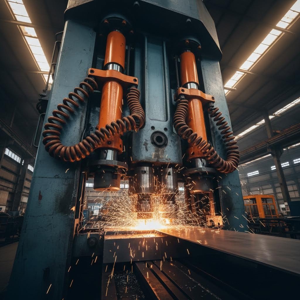
Understanding the Root Causes of Sheet Metal Deformation
Springback, wrinkling, cracking, and warping: Mechanisms and material dependencies
Sheet metal deformation during forming typically falls into four categories: springback, wrinkling, cracking, and warping. Springback occurs when the material partially recovers elastically after bending, causing the final angle to open beyond the tooling—up to 2° in low-carbon steels (ASM Handbook, 2022) and as much as 4° in high-strength aluminum alloys. Wrinkling arises from compressive stress exceeding the sheet’s buckling limit, especially in thin gauges or low-modulus materials like aluminum. Cracking initiates on the outer tensile surface once local strain surpasses formability limits; for example, 5052-H32 aluminum fractures above ~12% strain (ASTM E8, 2021). Warping reflects global distortion driven by non-uniform cooling or asymmetric residual stress distribution—common in long or narrow parts. Material selection directly governs these behaviors: alloys with a low yield-to-tensile ratio reduce springback; high-ductility grades resist cracking; and appropriate thickness helps suppress wrinkling.
Grain direction effects and residual stress buildup near bend lines
Rolled sheet metal exhibits anisotropic behavior due to directional grain orientation. Bending parallel to the grain (longitudinal direction) maximizes ductility and enables tighter radii without fracture. Bending perpendicular to the grain may require up to 50% larger bend radii for some aluminum alloys (Machinery’s Handbook, 2021), particularly in cold-worked tempers. Plastic bending also introduces steep residual stress gradients near the bend line: tensile stress on the inner radius commonly reaches 60–80% of yield strength (NACE, 2020), while compressive stress builds on the outer face. These locked-in stresses can trigger delayed cracking in service or exacerbate warping during subsequent machining or heat treatment. Aligning critical bends with the rolling direction—and applying post-form stress-relief treatments for high-strength components—effectively mitigates grain-related failures and residual stress-induced distortion.
Design Strategies to Minimize Sheet Metal Deformation
Feature placement rules: Minimum distances from bends and symmetry principles
Holes and cutouts placed too close to a bend line act as stress risers, increasing risk of tearing, wrinkling, or localized distortion. Industry press brake data (2023) shows that positioning holes at least 2.5–3× material thickness from the bend tangent reduces deformation risk by over 40%; for gauges above 3 mm, a 4× distance is recommended. This buffer allows controlled plastic flow without rupture. Symmetry further enhances stability: placing cutouts, louvers, and tabs symmetrically about the bend axis balances forming loads. Asymmetric features induce rotational moments in the die, leading to angle errors and twist. Finite element analysis (Sheet Metal Forming Research Group, 2024) confirms symmetrical layouts reduce post-bend shape deviation by 35% versus asymmetric ones. Integrating these rules early avoids costly prototyping iterations and ensures consistent, distortion-free production.
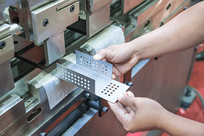
Balanced geometry and neutral axis alignment for uniform strain distribution
Unbalanced cross-sections shift the neutral axis away from the geometric center, causing uneven strain: shorter flanges experience excessive elongation (risking thinning and cracking), while longer ones compress and buckle. Aligning the neutral axis with the bend line ensures symmetrical deformation across inner and outer surfaces. This is achieved by equalizing flange lengths or integrating stiffening features—beads, ribs, or hems—that redistribute stress. Accurate k-factor calibration—the ratio of neutral axis offset to material thickness—is essential for predicting springback and adjusting bend allowances. A symmetric bending sequence (e.g., forming opposing bends simultaneously) further balances forces and minimizes distortion, as validated by press brake simulation studies. For complex or large-format parts, finite element analysis optimizes blank holder force and punch velocity to maintain neutral axis centrality throughout the stroke—reducing residual stresses that drive post-bend warping. Balanced geometry is especially critical for long, narrow enclosure panels, where minor misalignments compound into visible twist.
Optimizing Material-Specific Parameters to Control Sheet Metal Deformation
Minimum bend radius guidelines by alloy and thickness (steel, aluminum, stainless)
Selecting the correct minimum bend radius prevents cracking and excessive thinning. Low-carbon steels (e.g., AISI 1008) tolerate tight bends—0.5t to 1t (where t = thickness)—while aluminum alloys require greater radii due to lower ductility: 5052-H32 needs 1.5t–2t, and 6061-T6 typically requires 2t–3t (annealed 6061 may allow 1t). Stainless 304 demands 1t–2t because of rapid work hardening. These values assume bending perpendicular to the grain; bends parallel to the grain may permit tighter radii, but those oriented across the grain often require up to double the listed minimum to avoid fracture. For thicknesses above 3 mm, increase the radius by at least 50% of the lower bound.
| Material | Typical Minimum Bend Radius (t = thickness) |
|---|---|
| Mild steel | 0.5t – 1t |
| Aluminum 5052 | 1.5t – 2t |
| Aluminum 6061 | 2t – 3t (annealed may allow 1t) |
| Stainless 304 | 1t – 2t |
Die width, punch radius, and k-factor calibration for consistent deformation control
V-die opening width critically influences springback magnitude and required bend force. A general guideline is V = 6t to 12t, with softer materials (e.g., annealed aluminum) favoring the wider end to reduce pressure and improve control. The punch radius should be slightly smaller than the target inside bend radius—typically 0.8 to 1.0×—to compensate for elastic recovery. The k-factor calibrates flat-pattern development and bend allowance calculations: standard approximations are 0.33 for radius-to-thickness ratios < 2 and 0.5 for ratios > 2. However, precise control demands iterative validation—adjusting die width, punch radius, and k-factor based on trial bends and measured springback—particularly when switching alloys, tempers, or tooling setups.
Structural Relief Techniques for Reliable Sheet Metal Deformation Prevention
Structural relief techniques reliably prevent deformation by redistributing stress and reinforcing weak points—without adding weight or compromising function.
Bend reliefs and cutouts: Strategic placement to relieve stress concentration
Bend reliefs—narrow slots or notches cut at bend line termini—eliminate material buildup and prevent tearing or corner distortion. Properly sized, they allow flanges to form cleanly and reduce peak stress that contributes to warping. Relief width should match material thickness; depth must extend beyond the bend radius to fully isolate the flange from the web. Cutouts near bends require careful spacing: maintain a minimum distance of 2.5× material thickness plus the bend radius to preserve edge integrity and prevent unintended deformation. For parallel bends, staggered reliefs help balance strain distribution—especially beneficial in high-strength alloys prone to localized failure. This targeted approach significantly reduces stress concentration, improving bend angle consistency and overall part flatness.
Stiffeners—including beads, ribs, and hems—to enhance rigidity without increasing weight
Stiffeners increase section modulus to boost stiffness without thickening the base material. Beads—shallow, linear embossments—effectively suppress waviness and global warping in large flat panels; even a bead height equal to sheet thickness can increase stiffness by 40–60% over an unembossed blank when aligned with primary load paths. Ribs provide directional reinforcement and integrate well into corners to resist deformation during secondary operations. Hems—edges folded over themselves—deliver clean, safe finishes while adding localized rigidity; a hem ratio of 0.6–0.8× material thickness typically achieves optimal strength without cracking. Used strategically, these features enable down-gauging—reducing material thickness by one gauge size—while maintaining dimensional stability and performance, yielding lighter, more robust sheet metal components.
FAQ
What are the main causes of sheet metal deformation?
Sheet metal deformation is caused by four main factors: springback, wrinkling, cracking, and warping. These phenomena occur due to material properties like elasticity, ductility, and stress concentration from uneven cooling or stress distribution.
How can bending grain direction affect sheet metal deformation?
Bending along the grain can maximize ductility and allow tighter radii without fracturing while bending across the grain often requires increased radii to prevent cracking or warping.
What design strategies minimize sheet metal deformation?
Creating symmetry in feature placement, aligning the neutral axis, balancing geometry, and positioning holes and cutouts at appropriate distances from bends are crucial design strategies for minimizing deformation.
What is the role of minimum bend radius in controlling deformation?
The minimum bend radius, which varies based on material and thickness, prevents excessive thinning or cracking during bending operations and must be carefully chosen for each application.
What are bend reliefs and their importance?
Bend reliefs are narrow slots or notches cut along the bend line termini to relieve stress concentration. They ensure clean flange formation, reduce tearing, and minimize warping.
Why are stiffeners important in sheet metal design?
Stiffeners like beads, ribs, and hems provide additional rigidity without increasing the material weight, reducing defects like waviness or warping and enhancing durability.
Table of Contents
- Understanding the Root Causes of Sheet Metal Deformation
- Design Strategies to Minimize Sheet Metal Deformation
- Optimizing Material-Specific Parameters to Control Sheet Metal Deformation
- Structural Relief Techniques for Reliable Sheet Metal Deformation Prevention
-
FAQ
- What are the main causes of sheet metal deformation?
- How can bending grain direction affect sheet metal deformation?
- What design strategies minimize sheet metal deformation?
- What is the role of minimum bend radius in controlling deformation?
- What are bend reliefs and their importance?
- Why are stiffeners important in sheet metal design?