 Small batches, high standards. Our rapid prototyping service makes validation faster and easier —
  EN
EN

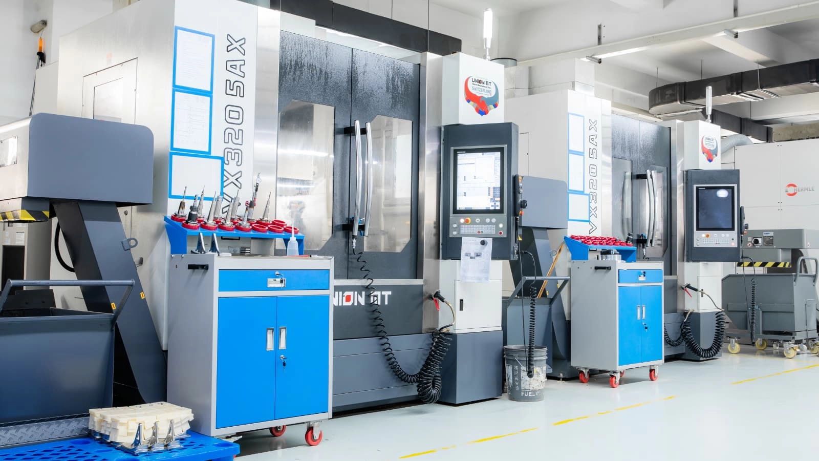
Key Technical Drivers of CNC Hole Precision
Achieving reliable CNC hole precision requires control over a triad of machine-, process-, and material-dependent variables. Three pillars—mechanical stability, thermal control, and workpiece hardness—directly govern the ability to hold bore diameters within tight tolerance bands. The following sections dissect each driver and its measurable impact on hole quality.
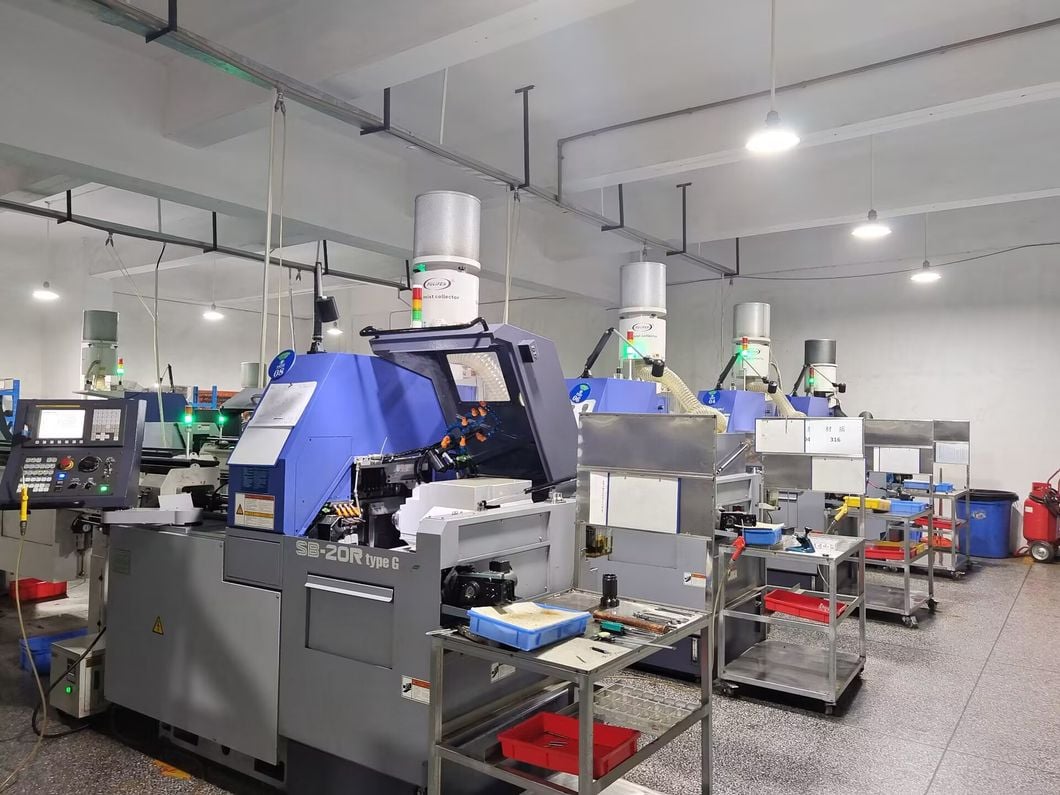
Tool rigidity and spindle stability: foundational factors for dimensional repeatability
Tool rigidity and spindle stability form the bedrock of repeatable hole dimensions. A slender tool holder or insufficient spindle clamping force introduces deflection under cutting loads, directly translating to positional error and bell-mouth entry. In a 2023 study of 40‑taper spindles, tool overhang beyond 4× diameter increased radial deviation by 0.015 mm per 100 mm of extension. Spindle runout below 2 µm is essential; a 5 µm runout alone can shift hole center by 0.01 mm. Stiffness pairing—using balanced shrink-fit holders and high‑rigidity collets—limits dynamic bending. For deep holes, modular damped bars reduce chatter, preserving roundness. Without this foundation, downstream processes like reaming cannot compensate for initial misalignment, locking in scrap from the first peck.
Thermal drift management: mitigating bore diameter variation (±0.005 mm) during extended runtime
Thermal expansion of spindle, ball screws, and tool shank creates a progressive bore diameter walk in long runs. A five‑axis machining center can see a 0.008 mm growth in spindle nose displacement after 30 minutes of warm‑up, enough to push an IT7 hole out of tolerance. Mitigation starts with a 15–20‑minute warm‑up cycle at operating speed, followed by coolant‑temperature stabilization to ±0.5 °C. Active cooling jackets on spindle motors and linear scales with thermal compensation maintain bore diameter within ±0.005 mm over hours. Real‑time monitoring of machine temperature gradients—with automatic offset adjustments—has been shown to halve size variation in a 200‑hole batch (Precision Engineering Journal, 2024). For high‑precision parts, shifting from batch to in‑cycle probing after every 50 holes catches drift before it exceeds limits.
Material hardness variability: quantifying its impact on hole size deviation in hardened steels
Hardness fluctuations in hardened steels (45–62 HRC) directly alter cutting forces and elastic recovery, causing unpredictable hole size deviation. A hardness increase of 5 HRC—typical within a single bar of 4140 steel—can raise thrust force by 8–12% and enlarge the hole by 0.008–0.012 mm as the material springs back less. For an H7 tolerance (0.018 mm band), this variation consumes half the allowance. Carbide drills with AlTiN coating and a 140° point angle resist edge wear, but consistent material temper remains dominant. Heat‑treat validation data showing hardness uniformity within ±1 HRC reduces size scatter by 30%, while micro‑hardness mapping of blanks before machining prevents tool deflection surprises. In one case, switching to a supplier with a controlled quench‑and‑temper process raised bore diameter CpK from 1.0 to 1.67—improving CNC hole precision without any tooling change.
Optimizing CNC Hole Precision Through Process Selection
Drilling vs. Boring vs. Reaming: Tolerance Capabilities (±0.1 mm to ±0.005 mm), Cycle Time, and Cost Trade-offs
Selecting the right hole‑making process is a direct lever on dimensional accuracy, throughput, and per‑part cost. Drilling, boring, and reaming each occupy distinct bands of capability, as summarized in the table below.
| Process | Typical Tolerance (Diameter) | Achievable Surface Finish (Ra) | Relative Cycle Time | Relative Cost per Hole | Best Application |
|---|---|---|---|---|---|
| Drilling | ±0.1 mm (IT12–IT13) | 3.2–6.3 µm | ★★★ (fastest) | $ (lowest) | Clearance holes, rough locating bores |
| Reaming | ±0.01 mm (IT7–IT8) | 0.8–1.6 µm | ★★ | $$ | Dowel fits, alignment bores with moderate precision |
| Boring | ±0.005 mm (IT6–IT7) | 0.4–0.8 µm | ★ (slowest) | $$$ | Bearing seats, sealing surfaces, high‑geometric‑integrity bores |
Drilling is the most material‑removal efficient, but the inherent flexibility of a twist drill limits positional accuracy and often leaves a bell‑mouthed or oversize hole. Reaming corrects size and surface finish for holes up to approximately 40 mm diameter, but it cannot fix positional or straightness errors introduced by the preceding drill. Boring—particularly with a single‑point adjustable bar—can correct both location and geometry; multi‑axis CNC boring heads allow real‑time diameter control to ±0.002 mm in closed‑loop systems, at the price of lower metal removal rates and higher tooling investment. For production volumes above 50,000 parts per year, annual tooling and cycle‑time costs often shift the economic balance from dedicated boring operations to reaming combined with tight pilot‑hole control—especially when concentricity tolerances below 0.01 mm are specified.
Multi‑Stage Boring Strategy: Achieving Roundness <0.003 mm and Concentricity <0.008 mm
When print requirements specify roundness better than 0.003 mm and concentricity within 0.008 mm, a single‑pass boring cut rarely suffices. Residual stresses, uneven stock allowance, and tool deflection cause progressive degradation of form accuracy. A staged approach—rough, semi‑finish, and finish boring—systematically eliminates these errors.
The rough‑boring pass removes the bulk of material (typically 0.3–0.5 mm on diameter), leaving 0.15–0.25 mm for the semi‑finish cut. At this stage, tool pressure is high, and the primary goal is to break the as‑drilled or as‑cast surface layer and establish a more symmetric cutting load. Semi‑finish boring takes a lighter depth of cut (0.07–0.12 mm) to refine the bore’s straightness and roundness to within 0.005 mm, while also reducing the impact of hard spots or inclusions. The finish pass—executed with a rigid, vibration‑damped boring bar—removes only 0.02–0.05 mm on diameter, generating a surface finish Ra ≤0.4 µm and pushing roundness below 0.003 mm. Concentricity is maintained by performing all boring stages on the same machine in a single clamping, using a boring head with known radial offset or a twin‑cutter configuration that balances cutting forces. Industry benchmarking data from 2023 shows that such three‑stage strategies reduce bore‑to‑bore location scatter by 67% compared to a single finish‑boring step, while concentricity variation stays under 0.005 mm across runs of 200+ aluminum alloy housings. The trade‑off is cycle time: a three‑stage cycle may take 2.5–4 times longer than a single pass, but the elimination of post‑process inspection and rework frequently yields a net cost saving for parts where out‑of‑spec bores cause functional rejects.
Precision Setup and Tooling Best Practices for CNC Hole Precision
Spot and pilot drilling as geometric anchors: eliminating drill wander (<0.02 mm) in high-aspect-ratio holes
Achieving reliable CNC hole precision in high-aspect-ratio bores—where depth exceeds 5× diameter—demands a rigid geometric anchor. Without a precise starting point, long drills deflect under feed forces, causing positional errors that often surpass 0.1 mm. Spot drilling initiates the process by creating a shallow, chamfered cone that guides the subsequent tool. Following immediately with a pilot drill, typically 0.5–1.0 mm undersized, further stabilizes the path and corrects any residual inclination. This two‑step sequence constrains radial deviation, with industry benchmarks showing that wander can be held below 0.02 mm. A properly executed spot‑and‑pilot strategy also reduces thrust load variation, extending tool life and maintaining hole position tolerance across batch runs. For instance, a leading aerospace supplier reduced scrap by 34% after implementing this method on hardened alloy components.
Cutting tool geometry and coating selection for optimal chip control and surface finish (Ra ≤ 0.8 µm)
Tool geometry and coating directly influence chip evacuation and resulting surface integrity. A split‑point or self‑centering drill point mitigates walking, while a high helix angle—typically 30–35°—lifts chips out of deep holes, preventing re‑cutting and built‑up edge. Specialized coatings further enhance performance. TiAlN (aluminum titanium nitride) reduces friction and withstands high temperatures, enabling smooth cutting and a surface finish of Ra ≤ 0.8 µm even in abrasive steels. For aluminum and non‑ferrous alloys, a diamond‑like carbon (DLC) coating minimizes material adhesion and produces a mirror‑like bore wall. Recent comparative studies confirm that matching the coating to the workpiece material can cut scrap rates by up to 20% while consistently meeting the Ra 0.8 µm benchmark.
Design-for-Manufacturing Constraints Impacting CNC Hole Precision
CNC hole precision is directly shaped by design-for-manufacturing (DFM) decisions that govern tool accessibility, deflection, and process capability. Hole depth-to-diameter ratios beyond 4:1 amplify drill wander and chatter; tolerances can degrade from ±0.02 mm to over ±0.1 mm as the tool extends deep into the workpiece. Standardizing hole diameters—0.1 mm increments up to 10 mm, 0.5 mm steps above—allows direct drilling with off‑the‑shelf bits, eliminating secondary boring that adds cost and cycle time. Because cylindrical cutters cannot produce sharp internal corners, designers must include radii; a minimum corner radius of 1.5 mm for a 10 mm end‑mill avoids stress risers and maintains achievable hole position accuracy. Blind holes deeper than three times their diameter restrict chip evacuation and coolant flow, increasing the risk of recutting and thermal drift. Applying tight tolerances selectively—only where assembly or function demands—balances precision with manufacturability, as over‑specifying forces slower feeds, specialized tooling, and higher reject rates. By aligning hole geometry, depth, and tolerance with tooling limits, engineers sustain consistent hole precision without introducing unnecessary complexity or cost.
FAQ Section
What are the key factors affecting CNC hole precision?
Key factors include tool rigidity, spindle stability, thermal drift control, material hardness variability, and design-for-manufacturing constraints.
How can thermal drift be mitigated during extended runtime?
Thermal drift can be mitigated through proper warm-up cycles, coolant temperature stabilization, active cooling systems, and real-time monitoring with automatic offset adjustments.
What are the advantages of multi-stage boring strategies?
Multi-stage boring enhances roundness and concentricity while reducing scatter and minimizing post-process rework despite a longer cycle time.
How does material hardness variability impact hole precision?
Hardness variability changes cutting forces and elastic recovery in materials, introducing deviations in hole size and consuming tolerance allowances.
What is the recommended strategy for high-aspect-ratio holes?
A spot-and-pilot drilling process can significantly improve positioning accuracy, reduce deflection, and minimize positional errors in high-aspect-ratio holes.