 Small batches, high standards. Our rapid prototyping service makes validation faster and easier —
  EN
EN

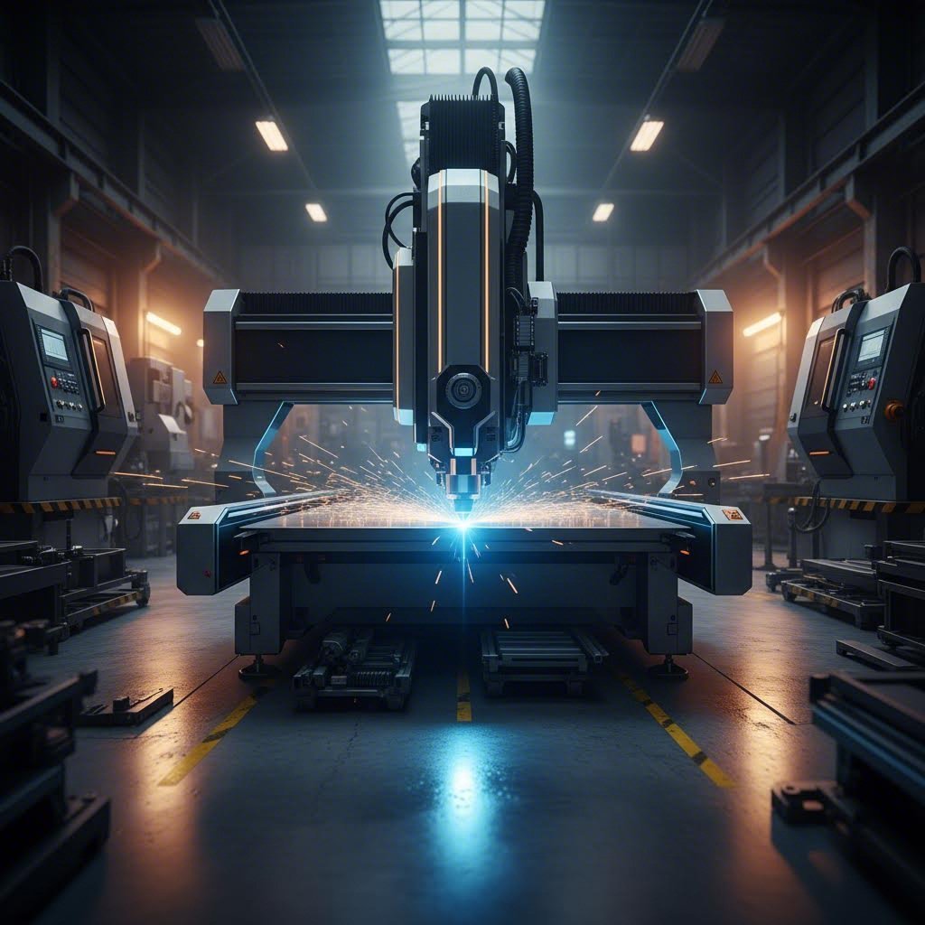
Strategic Nesting and Layout Optimization for Scrap Reduction
Algorithm-Driven Nesting: Maximizing Sheet Utilization in High-Mix Batch Runs
Advanced nesting algorithms are the backbone of modern scrap reduction in batch metal production. These computational tools arrange multiple part geometries on a sheet to minimize unused area—boosting material utilization by up to 20% compared to manual layouts. In high-mix, low-volume environments, the challenge lies not just in efficiency but in balancing scrap reduction with workflow continuity: over-production, storage of awkward remnants, and WIP buildup must all be avoided.
True-shape nesting software dynamically rotates and interconnects components, placing smaller parts into gaps that would otherwise become skeleton waste. Order-driven nesting prevents inventory accumulation but may leave sheet margins underutilized; conversely, inserting filler parts from future jobs raises yield—yet risks excess WIP if not governed by real-time order data. Modern systems intelligently select filler components only when the yield gain demonstrably outweighs inventory carrying costs.
Research from laser-cutting operations shows strategic nesting can reduce scrap rates from the industry average of 15–20% down to 8–12%, delivering immediate material savings. By transforming batch-specific layout decisions into a closed-loop, data-driven process, algorithm-driven nesting supports both scrap reduction and higher throughput.

Design for Manufacturability (DFM) Integration to Minimize Inherent Scrap at the CAD Stage
Scrap reduction begins before cutting—in the CAD model. Design for Manufacturability (DFM) principles embedded early prevent waste no nesting algorithm can recover. Overly tight internal corner radii, non-standard hole sizes, or inconsistent material thicknesses across a batch force extra processing, generate unusable trim, or create incompatible offcuts. DFM tools automatically flag such features and recommend adjustments—like replacing sharp corners with radii matching standard tooling—to eliminate unnecessary cuts.
Early consideration of grain direction and thermal distortion also avoids warped or dimensionally unstable parts that fail inspection later. Standardizing thicknesses within a batch further reduces leftover scrap between jobs. Shops enforcing consistent DFM checks see measurable drops in first-run scrap rates, as parts arrive ready for efficient nesting and fabrication. This proactive alignment of engineering intent with production reality embeds scrap reduction into the product lifecycle from the first digital file.
Precision Cutting Technology Selection to Lower Scrap Rates
Choosing the right cutting method directly determines how much material becomes scrap. Below, we compare three dominant technologies by performance across thickness ranges and alloy families—and show how to justify investment using break-even analysis.
Laser vs. Punching vs. Waterjet: Scrap Performance by Material Thickness and Alloy Family
Each precision cutting technology generates scrap differently depending on material thickness and metallurgical properties. The table below summarizes typical performance and practical selection guidance.
| Cutting Technology | Optimal Thickness | Alloy Families | Scrap-Reduction Characteristics |
|---|---|---|---|
| Fiber Laser | 0.5–25 mm | Mild steel, stainless, aluminum, copper alloys | Kerf as low as 0.2 mm (advanced systems under 0.5 mm); minimal edge-trim waste; tight nesting yields up to 30% less material loss vs. shearing. |
| Punching | 0.5–6 mm | Mild steel, ductile aluminum | Die clearance produces slug scrap; scrap rate climbs sharply with harder or thicker alloys. High-density nests can leave 8% of sheet area as unrecoverable slugs. |
| Waterjet | Up to 200 mm | Titanium, Inconel, tool steels, all non-ferrous | Kerf 0.5–1.5 mm; cold process eliminates heat-affected zones and warpage, but lower speed may constrain throughput. Ideal for thick exotic alloys where other methods risk micro-cracking. |
For batch runs in mild and stainless steels under 12 mm, fiber laser with intelligent nesting typically delivers the lowest scrap footprint. Advanced laser systems reduce kerf width to less than 0.5 mm—preserving usable material across thousands of cuts [Okon Recycling, 2023]. When working with ductile aluminum under 6 mm, punching remains fast—but requires precise die clearance optimization to avoid double-digit slug waste. Waterjet excels for thick aerospace alloys like titanium and Inconel, where laser heat may induce micro-cracking. Though its kerf is wider, the ability to nest multi-inch plate without distortion often offsets material loss—especially when alternative methods yield significantly higher scrap.
Shops that match cutting technology to alloy and thickness consistently report 15–20% lower overall scrap generation.
ROI of Precision Upgrades: Calculating Break-Even Based on Scrap Reduction Targets
The financial case for upgrading to a precision cutting system hinges on a clear, quantifiable return: annual material savings must recoup capital cost within an acceptable timeframe. Industry data shows 15–20% scrap reduction is typical after adopting laser or waterjet technologies [Okon Recycling, 2023]. For a facility spending $200,000 annually on wasted raw material, a conservative 15% improvement saves $30,000 per year. A $90,000 upgrade therefore breaks even in three years—often faster when factoring in reduced rework, accelerated throughput, and labor reallocation.
To calculate break-even precisely: track current scrap weight by material type, assign a dollar value per pound, then project the lower scrap rate from the proposed technology. Subtract any increased consumable or energy costs. Divide the net annual savings into the machine’s total installed cost to determine payback time—transforming scrap reduction targets into a defendable capital budget line.
Cross-Stage Scrap Reduction Through Process Integration and Feedback Loops
Identifying and Mitigating Scrap Hotspots Across Casting, Rolling, and Finishing Stages
Scrap reduction in batch metal production demands a cross-stage approach—because defects rarely originate where they’re detected. Casting inclusions, for example, may persist through rolling and only surface as finishing rejects, making isolated inspections insufficient.
To uncover hidden sources, manufacturers deploy sensor networks and Statistical Process Control (SPC) to monitor variation across each stage. When rolling thickness deviation correlates with elevated finishing scrap, root-cause analysis traces the issue back to casting parameters. Real-time finishing data can then automatically adjust upstream variables—such as casting temperature or rolling pressure—preventing defect propagation.
Cross-functional teams, led by dedicated scrap reduction champions, conduct weekly reviews of hotspot maps and implement rapid corrective actions. This integrated monitoring and response framework addresses problems where they begin—not where they appear—delivering sustained scrap reduction across the entire value stream.
FAQ Section
What is the role of nesting algorithms in scrap reduction?
Nesting algorithms arrange part geometries on a sheet to maximize material utilization, reducing unused areas and improving material usage by up to 20% compared to manual layouts.
How does Design for Manufacturability (DFM) help reduce scrap?
DFM principles flag problematic design features like tight corners and inconsistent thicknesses at the CAD stage. These adjustments help eliminate unnecessary cuts and improve first-run efficiency.
What cutting technology is best for minimizing scrap?
The best choice depends on material thickness and alloy family. Fiber lasers provide minimal kerf and high nesting efficiency for mild steels, while waterjets minimize waste for thick exotic alloys like Inconel.
How can break-even analysis justify a cutting technology upgrade?
Break-even analysis calculates savings from reduced scrap, factoring in costs like consumables. By comparing projected annual savings to investment costs, facilities can make informed decisions on upgrades.
Why is cross-stage process integration necessary for scrap reduction?
The origin of defects affecting scrap rates may trace back to earlier stages like casting. Integrated monitoring allows teams to preemptively mitigate these problems, improving efficiency across the entire production line.
Table of Contents
- Strategic Nesting and Layout Optimization for Scrap Reduction
- Precision Cutting Technology Selection to Lower Scrap Rates
- Cross-Stage Scrap Reduction Through Process Integration and Feedback Loops
-
FAQ Section
- What is the role of nesting algorithms in scrap reduction?
- How does Design for Manufacturability (DFM) help reduce scrap?
- What cutting technology is best for minimizing scrap?
- How can break-even analysis justify a cutting technology upgrade?
- Why is cross-stage process integration necessary for scrap reduction?