 Small batches, high standards. Our rapid prototyping service makes validation faster and easier —
  EN
EN


GD&T Flatness Fundamentals and Tolerance Specification for Flatness Control
ASME Y14.5 Flatness Definition: Datum-Referenced vs. Non-Datum Applications
Flatness is a form control in geometric dimensioning and tolerancing (GD&T) that limits a surface’s deviation from a perfect plane. Per ASME Y14.5, it is most frequently applied without a datum reference—meaning the tolerance zone is self-referenced and independent of other features. In this configuration, all points on the surface must lie within a 3D zone bounded by two parallel planes, spaced apart by the value in the feature control frame. This self-contained zone is essential for functional requirements like sealing, where local surface conformity—not orientation relative to other features—is critical.
In contrast, a datum-referenced flatness callout (sometimes termed “flatness on a unit basis” or used in composite controls) constrains the surface’s orientation relative to a specified datum plane. It does not govern form alone but integrates with the part’s mounting interface and overall assembly behavior. Misapplying a datum reference when only local flatness matters—such as specifying datum A for a gasket surface—can unnecessarily tighten tolerances. Industry data shows such over-constraint can inflate manufacturing costs by up to 30%, particularly for high-precision components like engine blocks, where localized flatness suffices for sealing performance.
Interpreting Flatness Tolerance Zones: Impact on Part Functionality and Assembly
The flatness tolerance zone defines a virtual, parallel-plane envelope within which the entire controlled surface must reside. A specification of 0.1 mm means the maximum allowable separation between those bounding planes is 0.1 mm. For hydraulic manifold faces, this ensures micro-flat contact under pressure—directly preventing fluid leakage, a leading cause of field failures in fluid power systems.
Real-world consequences are well documented: pressure-sensitive film studies show surfaces exceeding flatness tolerance can lose over 70% of effective contact area, resulting in uneven load distribution and accelerated wear. In bolted joints, excessive flatness error induces bending stresses in fasteners—a factor in roughly 20% of fatigue-related mechanical failures. The cost of late-stage correction is steep: industry research confirms rectifying flatness issues after assembly is approximately 10× more expensive than catching them during production, with the average cost of an assembly-line stoppage due to non-conforming parts exceeding $740,000 (Ponemon Institute, 2023). Thus, precise interpretation and consistent application of flatness tolerances serve not just as design criteria—but as strategic levers for warranty cost control and long-term reliability.
Flatness Control in Stamped Parts: Process, Material, and Tooling Strategies
Controlling flatness in stamping demands a system-level strategy integrating process parameters, tooling design, and material behavior. Success hinges on addressing root causes—not just correcting symptoms—particularly springback, warpage, anisotropy, and residual stress.
Compensating for Springback and Warpage in Press Brake and Progressive Die Stamping
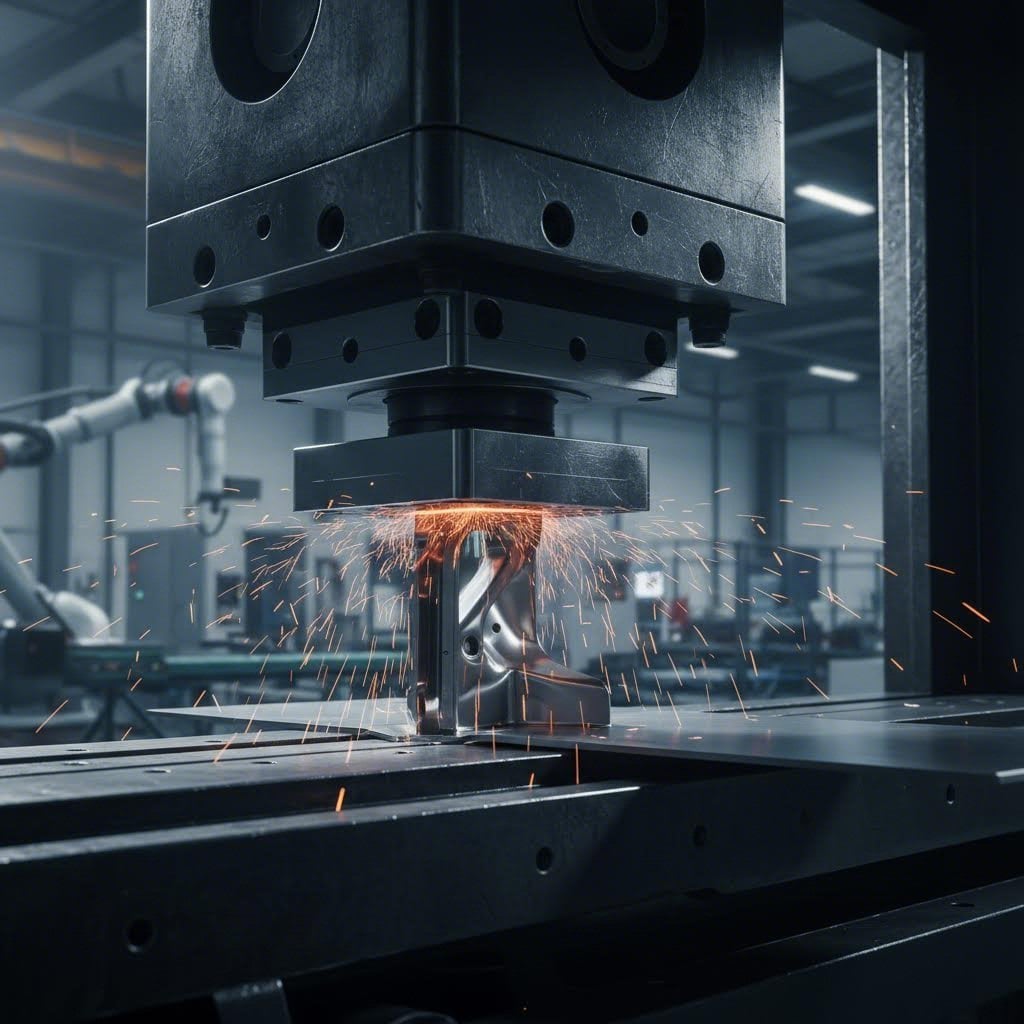
Springback—the elastic recovery of material after forming—is the dominant source of flatness deviation in stamped parts. Effective compensation involves intentionally overforming the part so it relaxes into the target geometry. Finite Element Analysis (FEA) is widely used to predict springback magnitude and direction, enabling pre-compensation in die design. Progressive dies often implement multi-stage forming, where each station progressively shapes and stress-relieves the material, minimizing internal stress buildup. For example, a major manufacturer achieves consistent flatness within 0.05 mm on 316L stainless steel parts using stress-engineered, pre-compensated dies.
Warpage arises from non-uniform thermal and mechanical stress distribution—often exacerbated by friction, heat, or inconsistent press force. Excessive speed increases thermal input and promotes distortion; insufficient force leads to incomplete forming and unstable geometry. Optimal control requires real-time monitoring of tonnage and tightly regulated press speed to balance energy input and deformation fidelity.
Mitigating Material Anisotropy and Residual Stress Effects on Sheet Metal Flatness
Material anisotropy—directional variation in yield strength and elongation—causes uneven flow during forming, resulting in differential strain and loss of flatness. Mitigation begins upstream: optimizing blank shape and grain orientation relative to the die using CAE simulation allows engineers to anticipate and preempt distortion before tooling is cut.
Residual stresses—locked-in from prior rolling, cutting, or handling—can release asymmetrically during stamping, causing long-term warping. A proven countermeasure is pre-stamping stress relief: normalizing or annealing sheet metal homogenizes its microstructure, improves formability, and reduces post-forming distortion. Combined with controlled storage, proper lubrication, and strict incoming material verification, these steps significantly enhance flatness repeatability.
| Root Cause of Flatness Error | Core Mitigation Strategy | Key Process Control |
|---|---|---|
| Material Anisotropy | Optimize blank orientation and shape using CAE simulation. | Specify material grain direction; control incoming material tolerances. |
| Residual Stress | Pre-process stress-relief annealing or normalizing. | Controlled storage, handling to prevent pre-stamping deformation, and proper lubrication to minimize friction-induced stress. |
Flatness Control in CNC Machined Parts: Fixturing, Cutting, and Post-Process Stability
Fixture Design Principles to Minimize Distortion During Milling and Turning
Fixturing is the first line of defense against machining-induced flatness errors. Uneven clamping forces generate bending moments—especially problematic for thin-walled or large-span parts. Multi-point fixturing (e.g., hydraulic chucks, vacuum tables) delivers uniform support without localized stress concentrations. For delicate or low-rigidity components, custom soft jaws and low-profile vacuum fixtures maintain full-surface contact, eliminating lift or deflection during light finishing cuts.
Crucially, fixtures must avoid over-constraining: they should locate and secure the part while permitting controlled relaxation of residual stresses. In turning, balanced, center-aligned chucks and steady rests mitigate radial distortion. Whenever feasible, stress-relieving the workpiece—via vibratory or thermal treatment—before final machining dramatically improves dimensional stability. These practices routinely reduce flatness deviation from >0.3 mm to <0.05 mm across a 100 mm span.
Thermal Management and Sequential Machining Strategies for Dimensional Stability
Heat generated at the tool–workpiece interface is a primary driver of out-of-flatness. Localized expansion followed by non-uniform cooling can leave convex or concave distortions. High-volume coolant flood—precisely directed at the cutting zone—extracts heat efficiently and stabilizes the thermal gradient. Equally important is machining sequence: aggressive roughing should be followed by a full ambient cooldown before finish passes. Alternating sides—for instance, milling one face, flipping, then milling the opposite—balances residual stress release. For large plates, a “skim–flip–skim” routine with minimal depth-of-cut on the final pass ensures uniform surface integrity. In-process probing with real-time feedback detects thermal drift and enables automatic toolpath adjustment. Together, these methods enable flatness of 0.02 mm per 100 mm—even in thermally sensitive materials like aluminum and austenitic stainless steels.
Flatness Measurement, Validation, and Continuous Improvement for Flatness Control
Comparative Accuracy of Surface Plate, CMM, and Optical Profilometry for Production Inspection
Selecting the right measurement method aligns inspection capability with functional requirements, tolerance class, and throughput needs. Surface plate inspection—using dial indicators or height gauges on a granite reference plane—is fast and economical for small-to-medium parts, resolving deviations down to ~25 µm. However, manual point sampling limits coverage and repeatability, making it best suited for quick go/no-go checks or low-risk applications.
Coordinate measuring machines (CMMs) offer superior accuracy (±1 µm typical) and statistical repeatability through dense, automated point-cloud acquisition. While slower and more capital-intensive, CMMs are ideal for first-article validation, capability studies (e.g., Cp/Cpk), and high-value components requiring traceable metrology.
Optical profilometry and laser interferometry provide non-contact, full-field mapping—capturing millions of points in seconds with sub-micron vertical resolution. These systems excel on thin, flexible, polished, or heat-sensitive surfaces where probe deflection or thermal influence would compromise results. Limitations include sensitivity to vibration, reflectivity, and transparency—necessitating environmental controls and surface preparation.
A robust production strategy often layers these methods: surface plates for operator-level verification, CMMs for process monitoring and SPC, and optical scanning for 100% inline flatness control on critical surfaces. Matching the metrology method to part geometry, material, tolerance, and volume ensures flatness targets are consistently verified—and improvement efforts remain grounded in reliable, actionable data.
Frequently Asked Questions (FAQs)
Q: What is flatness in GD&T?
A: Flatness in GD&T is a geometric tolerance that controls the deviation of a surface from an ideal flat plane. It ensures the surface lies within two parallel planes that are spaced apart by a designated tolerance value.
Q: How is flatness tolerance applied without a datum reference?
A: Without a datum reference, flatness controls an individual surface independently. The surface must meet the flatness tolerance without orientation or relationship to any other feature.
Q: Why is springback significant in stamped parts?
A: Springback occurs when a material elastically recovers after forming, causing deviations from the intended geometry. Addressing this is critical for achieving required flatness in stamped components.
Q: What are common tools for measuring flatness?
A: Common tools include surface plates with dial indicators, coordinate measuring machines (CMMs), and optical profilometry systems, each suited to specific applications and tolerances.
Q: How can thermal management improve CNC machining flatness?
A: Effective thermal management using coolant and balanced machining sequences minimizes material distortion caused by heat, which improves dimensional stability and flatness during CNC machining.
Table of Contents
- GD&T Flatness Fundamentals and Tolerance Specification for Flatness Control
- Flatness Control in Stamped Parts: Process, Material, and Tooling Strategies
- Flatness Control in CNC Machined Parts: Fixturing, Cutting, and Post-Process Stability
- Flatness Measurement, Validation, and Continuous Improvement for Flatness Control