 Small batches, high standards. Our rapid prototyping service makes validation faster and easier —
  EN
EN

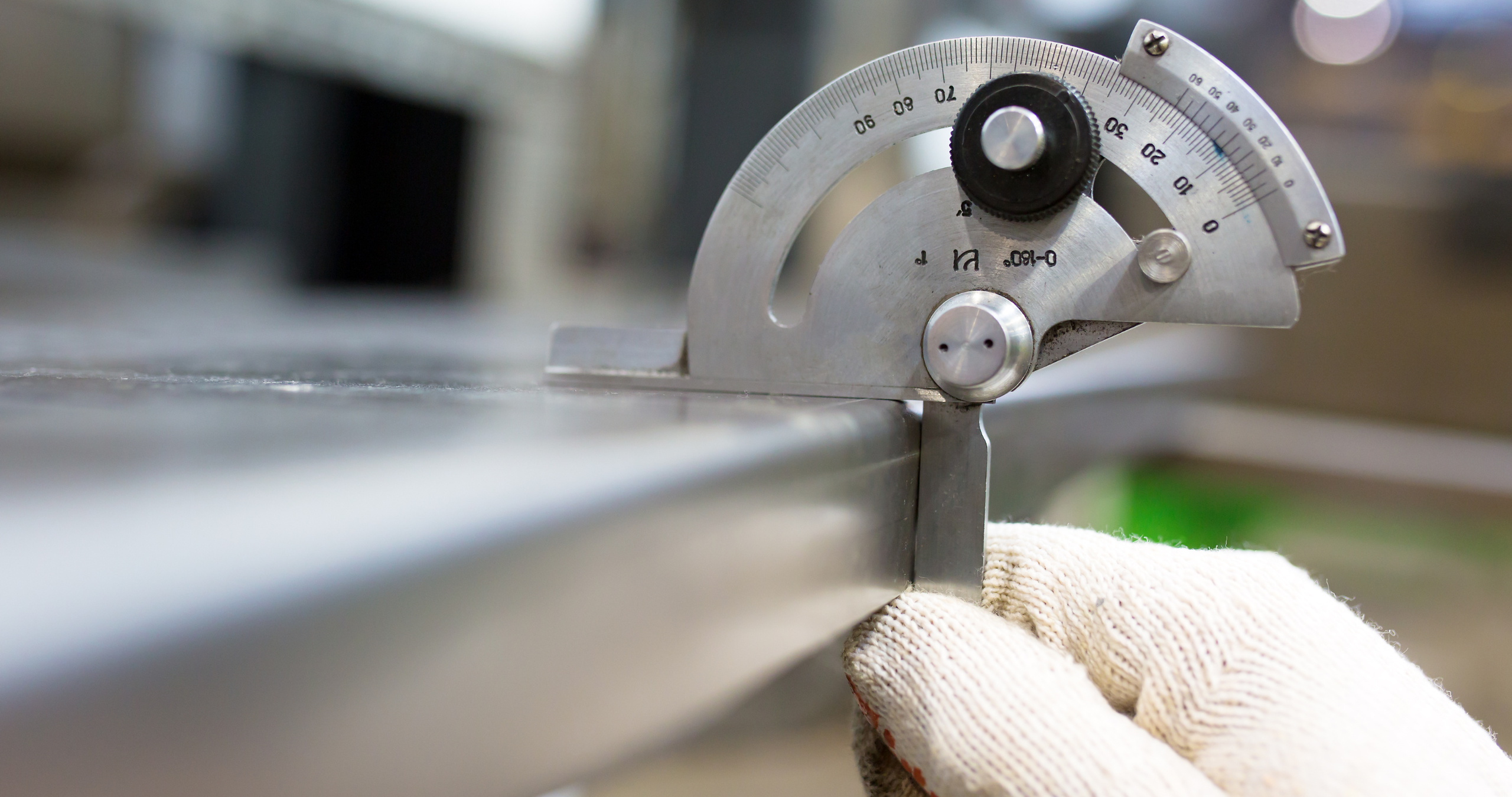
Start with Design for Manufacturability (DFM) Principles
Why Early DFM Integration Prevents Costly Redesign Loops
Integrating DFM analysis at the very beginning of metal part design is one of the most effective ways to eliminate costly redesign cycles. When manufacturing constraints are considered only after the design is frozen, even minor changes can force a cascade of revisions to tooling, fixtures, and process plans. A widely cited finding from the National Institute of Standards and Technology (NIST) indicates that a design change made during production can cost ten times more than one resolved in the concept phase. Early DFM bridges the gap between engineering intent and shop floor reality, flagging issues like overly thin walls, unnecessary undercuts, or impractical tolerances before they become embedded in the model. This proactive approach not only reduces the number of engineering change orders but also accelerates time-to-market. For metal part design specifically, early collaboration with manufacturing engineers helps identify opportunities to combine features, simplify tool paths, and select materials that perform well under intended process conditions. By embedding manufacturability checks into the initial design workflow, teams avoid the frustration of late-stage loops that drain budgets and delay delivery.
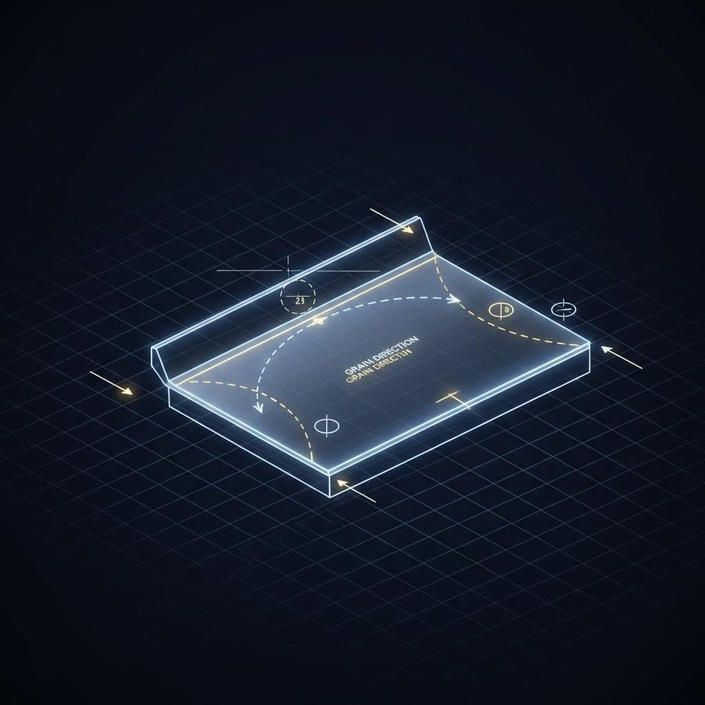
Practical CAD-Based DFM Checks for Metal Part Design
Modern CAD tools offer built-in checks that instantly validate metal part designs against manufacturability rules. Engineers should set up templates that automatically flag features like holes placed too close to bends, small radii requiring special tooling, or wall thicknesses below the recommended minimum for the chosen material. For example, a rule checking hole-to-edge distance prevents tearing during forming, while draft angle verification is essential for cast or forged components. Parametric modeling enables rapid what-if analysis—adjusting bend radii and instantly seeing the impact on blank size and material utilization. These checks are not a substitute for expert review, but they catch a large percentage of common errors early. A 2023 survey of contract manufacturers found that 40% of quote delays stem from designs failing basic DFM rules. By embedding these checks into the CAD environment, designers can iteratively refine their metal part design, ensuring every feature is justified by function and aligned with the capabilities of the intended production process.
Eliminate Non-Value-Adding Complexity in Metal Part Design
Distinguishing Functional Complexity from Manufacturing Overhead
In metal part design, every feature in a CAD model translates into machine movements, tool changes, and setup time. Designers often add complex curves, decorative fillets, or multiple varying radii that serve no functional purpose—these are pure manufacturing overhead. Functional complexity—such as a rib for structural integrity or a precise locating surface—directly contributes to part performance. Overhead, however, increases cost without adding value. For instance, a housing with rounded corners requires multiple tool changes and specialized programming, while a sharp-cornered version with chamfers performs identically at a fraction of the cost. Simplification strategies include replacing complex curves with straight lines and standard radii, consolidating small features into larger ones, and designing within generous tolerances. By examining each design element through a cost-benefit lens, engineers can preserve essential function while stripping away waste. This approach not only reduces machining time but also lowers the risk of defects, as simpler geometries are easier to manufacture and inspect.
Cost-Effective Alternatives: Progressive Stamping and Precision Bending
When sheet metal parts are involved, progressive stamping and precision bending offer powerful ways to avoid overcomplicated machining. Progressive stamping uses a single die set to perform multiple operations—such as piercing, forming, and cutting—in a continuous strip, drastically reducing per-part cost and complexity for high-volume production. Precision bending, when combined with standardized bend radii and thoughtful sequencing, eliminates the need for intricate multi-axis milling. Instead of designing a part with numerous unique bend angles, engineers can consolidate bends into a few standard angles, which simplifies tooling and reduces setup changes. This shift from general machining to dedicated forming processes aligns with Design for Manufacturability (DFM) principles, ensuring that the final design remains both functional and economical. By leveraging these alternatives, teams can cut lead times, minimize scrap, and improve overall part consistency.
Optimize Sheet Metal Bend Geometry and Tolerancing
Avoiding the K-Factor Pitfall in Bend Allowance Calculations
Overlooking the K-factor in metal part design leads to inaccurate flat patterns and costly rework. The K-factor defines the neutral axis shift during bending, and using a generic value like 0.5 for all materials and thicknesses is a common mistake. In reality, the K-factor varies with material type, thickness, and bend radius—typical ranges are 0.33 to 0.50. Failing to calibrate it causes bend allowance errors that stack up across multiple bends. For instance, with a ±0.010″ tolerance per bend, a five-bend part can drift by ±0.050″. Engineers should verify the K-factor through empirical testing or supplier data, and then embed it into CAD bend tables. A miscalculated flat pattern can waste material and delay delivery, adding unnecessary cost to the project. This simple step eliminates guesswork, reduces prototyping iterations, and keeps production on schedule.
Standardize Critical Dimensions to Accelerate Production
Material Thickness and Hole Size Standardization Benefits
In metal part design, standardizing critical dimensions like material thickness and hole diameters drastically reduces manufacturing complexity. By limiting the range of sheet metal gauges to a single or few common thicknesses, shops can avoid frequent tooling adjustments and streamline inventory management. Similarly, adopting a set of standard hole sizes—such as those matching off-the-shelf hardware—eliminates the need for custom punches and simplifies CNC programming. This consistency cuts setup time; for instance, fabricators report up to 30% faster changeovers when hole patterns are standardized. Moreover, procurement benefits from bulk purchasing of uniform materials, while quality control becomes more predictable. Ultimately, dimension standardization accelerates production from prototype to full-scale manufacturing, reducing lead times and costs without sacrificing part functionality.
FAQ
What is Design for Manufacturability (DFM)?
Design for Manufacturability (DFM) is a set of engineering principles focused on optimizing product designs for ease of manufacturing. It helps reduce production costs, minimize defects, and streamline workflows.
Why is early DFM integration important in metal part design?
Early DFM integration prevents costly redesign cycles by identifying manufacturing constraints during the concept phase. This approach accelerates time-to-market and minimizes late-stage engineering change orders.
What role do CAD tools play in DFM practices?
Modern CAD tools provide built-in checks that validate designs against manufacturability rules, flagging common errors like improper hole placement or incorrect wall thickness early in the design phase.
How can designers eliminate unnecessary complexity in metal part designs?
Designers can distinguish between functional complexity and manufacturing overhead, simplifying geometries like curves and radii to reduce machining time and production costs.
What are progressive stamping and precision bending?
Progressive stamping is a manufacturing process where multiple operations are performed on a single die set, suitable for high-volume production. Precision bending simplifies tooling setups by consolidating bend angles into fewer standard configurations.
Why is K-factor important in bend geometry calculations?
The K-factor defines the neutral axis shift during bending, and accurate calibration prevents errors in flat patterns, reduces rework, and ensures consistent production quality.
What are the benefits of standardizing material thickness and hole sizes?
Standardization simplifies tooling adjustments, streamlines inventory management, accelerates production setups, and ensures uniformity in mass production.
Table of Contents
- Start with Design for Manufacturability (DFM) Principles
- Eliminate Non-Value-Adding Complexity in Metal Part Design
- Optimize Sheet Metal Bend Geometry and Tolerancing
- Standardize Critical Dimensions to Accelerate Production
-
FAQ
- What is Design for Manufacturability (DFM)?
- Why is early DFM integration important in metal part design?
- What role do CAD tools play in DFM practices?
- How can designers eliminate unnecessary complexity in metal part designs?
- What are progressive stamping and precision bending?
- Why is K-factor important in bend geometry calculations?
- What are the benefits of standardizing material thickness and hole sizes?