 Small batches, high standards. Our rapid prototyping service makes validation faster and easier —
  EN
EN

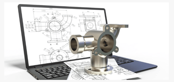
The Real Cost of Poor Sheet Metal Manufacturability
Production delays from rework loops and engineering change orders (ECOs)
When sheet metal designs lack manufacturability, each iteration often triggers a formal Engineering Change Order (ECO)—a process that typically takes 5–15 business days and engages engineering, procurement, and production teams. Common root causes include flanges placed too close to bends, unrealistic weld specifications, and unresolvable tolerance conflicts. These issues force repeated rework loops, extending lead times by weeks and disrupting entire production schedules. Each ECO adds $500–$2,000 in administrative and engineering time; across dozens of parts, cumulative costs can exceed $100,000 per project. Crucially, addressing manufacturability early—ideally during concept or detailed design—can reduce unit costs by 20–30%, according to PwC (2023). A leading garage door manufacturer exemplifies this: by redesigning a structural arm for roll forming using high-strength steel, they cut material content by 55%, saved over $550,000 annually, and reduced freight expenses by $120,000. Beyond direct cost, these delays consume valuable machine time otherwise available for revenue-generating work—and risk missing customer commitments.
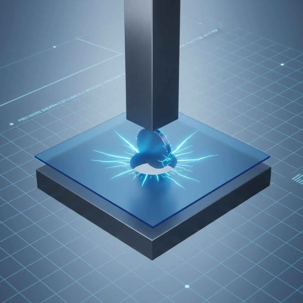
Material waste spikes due to scrap rates exceeding industry benchmarks (12–18% vs. optimal 3–5%)
Poor manufacturability drives scrap rates well above the optimal 3–5% benchmark—commonly to 12–18%. This waste stems from cracking during bending, weld burn-through, misaligned holes, and part distortion that renders blanks unusable. Excess scrap inflates raw material spend, disposal fees, and energy use—not to mention the hidden cost of rework and delayed shipments. For a typical shop processing 100 tons of steel monthly, reducing scrap by just 10 percentage points translates to $30,000–$50,000 in monthly savings. On a $200,000 material spend, the difference between a 15% and 5% scrap rate equals $20,000 in direct waste alone. As demonstrated by the same garage door manufacturer, optimizing geometry and material selection—not just process control—is essential to hitting target scrap levels.
Part failure in assembly or field use linked to unvalidated bend geometry and tolerance stack-up
Unvalidated bend geometry and unchecked tolerance stack-up directly compromise fit, function, and reliability. Parts with undersized bend radii, inconsistent flange lengths, or poorly positioned features frequently fail during assembly—causing costly line stoppages that run thousands of dollars per hour. In service, tight bend radii induce stress concentrations that accelerate fatigue cracking. A 2023 study of automotive warranty claims found 12% of failures traced to sheet metal design flaws—particularly unvalidated bend geometry and cumulative tolerances. Field failures trigger recalls, warranty payouts averaging $500–$1,500 per incident, and lasting brand damage. Misalignment in welded assemblies further compounds risk, requiring manual rework and increasing latent defect probability. Early validation—via finite element analysis, DFM checks, and physical prototyping—ensures parts meet both functional and assembly requirements. The cost of one field failure far exceeds the investment needed to prevent it.
Top 3 Design Features That Break Sheet Metal Manufacturability
Flanges too close to bends: violating minimum flange-to-bend distance rules (<2× material thickness)
A flange placed too near a bend line prevents proper press brake tooling engagement—leading to incomplete forming, tool collision, or distorted geometry. Industry standards require a minimum flange length of at least two times the material thickness (2T) to allow full V-die support. Violating this rule forces secondary operations or custom tooling, raising per-part cost by 15–25% and extending lead times. One manufacturer experienced a 30% rework increase after specifying a 1.5 mm flange on 1.2 mm steel—causing tool interference and inconsistent angles. Increasing the flange to 2.4 mm resolved the issue instantly. Embedding CAD-based bend-distance checks early in design prevents such oversights and preserves manufacturability without sacrificing functionality.
Unrealistic welds and improper U-channel ratios causing distortion and fixture incompatibility
Continuous welds on thin-gauge U-channels—or channels with depth-to-width ratios exceeding 1.5:1—introduce excessive heat input and asymmetric stress, resulting in angular distortion and fixture mismatch. For example, a 50 mm deep × 20 mm wide channel (ratio 2.5:1) concentrates stress at the weld toe, warping the profile. A 2023 European Welding Association study confirmed intermittent stitch welds reduce distortion by 40% versus full-length fillets on 1.5 mm galvanized steel—without compromising strength. Fixture compatibility also suffers when narrow return flanges leave insufficient clearance for standard clamps: a 20 mm-wide channel with a 5 mm return offers only 10 mm of usable opening, blocking toggle clamp engagement. Adhering to depth-to-width ratios between 1:1 and 1.5:1—and specifying intermittent weld patterns—avoids post-weld straightening, custom jigs, and cycle-time penalties.
Critical CAD and Tolerancing Pitfalls Affecting Sheet Metal Manufacturability
Bend radius mismatches and perpendicular corner conflicts triggering press brake tooling failures
Specifying bend radii smaller than the material’s mechanical minimum—especially without accounting for alloy, thickness, or grain direction—leads to cracking, tearing, and tool damage. A 2023 industry survey found 30% of press brake tooling failures stemmed from geometry exceeding tool limits. Perpendicular corners compound the problem: without adequate relief, the bend interferes with the tool shoulder, causing jamming, uneven force distribution, and inconsistent angles. For mild steel, the recommended minimum radius is typically 1× material thickness; harder alloys may require 2× or more. Unchecked, such mismatches raise scrap by up to 8% and disrupt scheduled throughput. Integrating automatic bend radius validation into CAD ensures every feature respects real-world tooling constraints—protecting both part quality and equipment uptime.
Hole placement errors near bends or in high-stress zones compromising structural integrity
Holes located too close to bend lines deform during forming—stretching edges, distorting features, and initiating cracks. A leading fabricator attributed 22% of its 2024 part rejections to misplaced holes. Industry best practice mandates a minimum distance of 1.5× material thickness from the hole edge to the bend tangent. In load-bearing flanges, weld zones, or other high-stress areas, holes act as stress concentrators—accelerating fatigue failure even under nominal loads. Tolerance stack-up can further shift hole position post-bending, rendering assemblies impossible to assemble. Prevention requires two complementary strategies: rule-based CAD alerts that flag noncompliant placements during modeling, and intentional use of post-forming drilling where design constraints demand tight clearances. Validating hole location early eliminates cracked protrusions, loose fits, and field failures—directly strengthening manufacturability and product reliability.
Proactive Strategies to Ensure Sheet Metal Manufacturability
Integrating DFM-aware CAD plugins and rule-based validation early in design
DFM validation must occur upstream—in the CAD environment—rather than as a downstream gate. Modern CAD platforms support plug-ins that embed sheet metal manufacturability rules directly into the design workflow. These tools automatically check bend radii, flange-to-bend distances, hole-to-edge clearance, and K-factor consistency against live material and tooling databases. Designers receive real-time alerts when a feature violates hard constraints—such as a flange shorter than 2T—enabling correction while the part remains virtual. According to the Fabricators & Manufacturers Association (2023), early rule-based validation cuts rework loops by 40%. Automating these checks replaces reliance on tribal knowledge, accelerates design sign-off, and avoids costly ECOs and tooling collisions. The result is a robust design file that passes first-article inspection more consistently, sustains scrap at optimal 3–5% levels, and keeps press brakes operating at planned capacity.
FAQ
What is an Engineering Change Order (ECO) and why does it impact costs?
An Engineering Change Order (ECO) is a formal process to modify designs or specifications during production. ECOs lead to increased administrative and engineering costs, which can add up to $500–$2,000 per instance, and extend lead times.
How can scrap rates be reduced in sheet metal manufacturing?
Scrap rates can be minimized by optimizing geometry, material selection, and embedding rule-based validation into the design process. Scrap below 5% is achievable by addressing root causes such as cracking during bending and misaligned holes.
Why are bend radii important in sheet metal design?
Bend radii influence the mechanical reliability of the part and prevent tooling failure. Specifying proper radii ensures parts are formed without cracking or damage and helps maintain structural integrity.
What are the benefits of rule-based validation in CAD?
Rule-based CAD validation ensures designs comply with manufacturability standards by identifying errors like incorrect bend radii or improper flange distances. Early validation eliminates ECOs and reduces rework loops.