 Small batches, high standards. Our rapid prototyping service makes validation faster and easier —
  EN
EN


Understanding Core Part Requirements: Tolerance, Geometry, and Function
Why dimensional tolerance drives process selection more than material or size
Dimensional tolerance—the permissible variation in a part’s physical measurements—shapes the manufacturing process far more than raw material choice or overall size. While teams often prioritize material grade or envelope dimensions, it is precision requirements that most decisively constrain process options. A specification of ±0.005 mm, for example, typically eliminates conventional stamping and directs selection toward CNC machining or high-end additive manufacturing. Material substitutions (e.g., aluminum to steel) may require minor tooling or feed-rate adjustments—but tightening tolerance from ±0.1 mm to ±0.01 mm forces a fundamental shift, such as moving from mill-turn centres to jig grinding. This is because process capability indices like Cpk are defined by measurable, repeatable dimensional spread—not material properties. So the part requirements process must begin with tolerance: it sets the baseline for achievable accuracy, scrap risk, and cost before any other variable enters the equation.
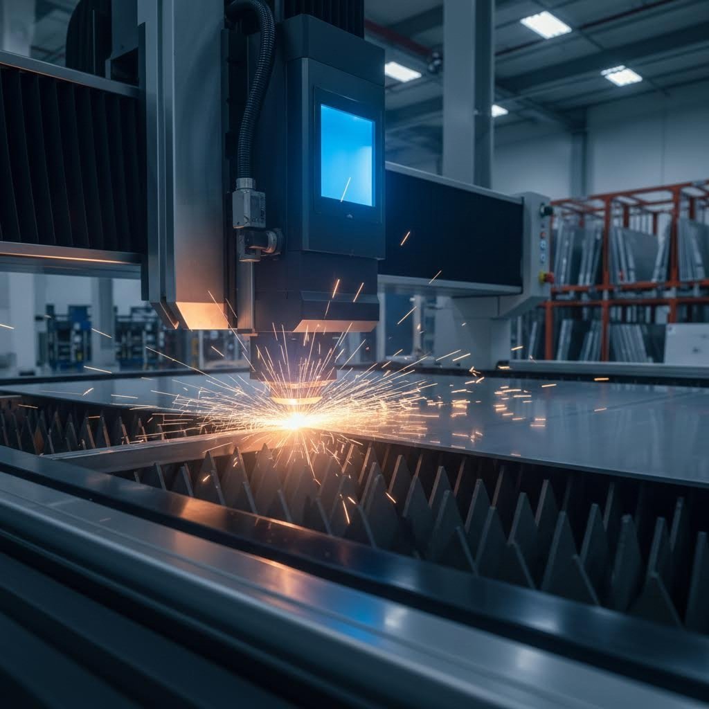
How functional intent (e.g., load-bearing vs. cosmetic) redefines ‘acceptable’ geometry
Functional intent—whether a part must carry structural loads, ensure sealing, or deliver visual perfection—radically redefines what “acceptable” geometry means. For a load-bearing bracket, surface waviness of 0.2 mm may be functionally irrelevant if stress distribution remains within safe limits; for an automotive interior trim piece, that same deviation would trigger a visual reject. This distinction shifts focus from global dimensional control to feature-specific tolerancing. Load-bearing parts demand uniform wall thickness, controlled fillet radii, and consistent grain flow—making forging or CNC machining ideal. Cosmetic parts emphasize surface finish, colour consistency, and parting-line placement—favouring injection moulding with polished tooling. Anchoring geometry to function prevents over-specification: a gear tooth flank under cyclic Hertzian contact requires tight profile tolerances no decorative ridge ever needs. By grounding acceptable geometry in real-world performance—structural integrity, fluid sealing, or aesthetic fidelity—engineers ensure the selected process delivers the right quality, at viable cost and lead time.
Mapping Requirements to Process Capabilities: A Practical Framework
The capability–requirement gap: Identifying mismatches before quoting or design freeze
Part requirements describe an ideal state—but every manufacturing process has inherent limitations. A 2023 study from the Advanced Manufacturing Research Center found that 37% of parts requiring rework suffered from capability-requirement gaps identified only after production began. These mismatches commonly appear when geometric tolerances exceed machine repeatability or when specified surface finishes demand secondary operations not originally planned.
Detecting these gaps early prevents cost overruns and protects project timelines. The core part requirements process demands direct comparison between each specification and a candidate process’s proven capabilities. For instance, ±0.005 mm is routine for CNC turning but unattainable for basic stamping; a complex internal channel easily built via laser powder bed fusion (LPBF) may drive prohibitive cost in traditional subtractive methods. Evaluating feasibility before design freeze avoids rushed redesigns and unplanned tooling investments. Proactive alignment also gives sourcing teams accurate data to negotiate realistic lead times—preventing the surprise of a “non-conforming” verdict after first-article inspection.
Comparative benchmark: CNC milling, turning, additive, and stamping across 7 key capability dimensions
A structured side-by-side evaluation clarifies which manufacturing method best fits a given set of part requirements. The table below contrasts four common processes across seven dimensions that directly influence production feasibility and cost.
| Capability Dimension | CNC Milling | CNC Turning | Additive (LPBF) | Stamping |
|---|---|---|---|---|
| Dimensional Tolerance (typical) | ±0.01 mm | ±0.005 mm | ±0.1 mm | ±0.05 mm |
| Geometry Complexity | High (3-axis, multi-axis) | Medium (rotationally symmetric) | Very high (organic, internal features) | Low (2.5D, simple forms) |
| Surface Finish (Ra) | 0.8–1.6 µm | 0.4–0.8 µm | 6–15 µm (as-built) | 1.0–2.5 µm |
| Material Range | Metals, plastics, composites | Primarily metals | Metals, polymers, ceramics | Sheet metals (steel, aluminum, copper) |
| Production Speed (per unit) | Moderate | Fast (for cylindrical parts) | Slow (hours) | Very fast (strokes per second) |
| Cost at 1,000 units | Medium-high | Medium | High | Low |
| Scalability to High Volumes | Limited by machine time | High through multi-spindle | Currently limited | Excellent (progressive dies) |
This mapping highlights inevitable trade-offs. A precision shaft with tight concentricity aligns naturally with turning; a bracket with simple holes and flanges leverages stamping’s cost advantage. Using such benchmarks before engaging suppliers curbs over-specification—revealing where tolerances can be relaxed on non-critical features without compromising function, thereby reducing per-unit cost while preserving part requirements process integrity.
Integrating DFM/DFA Early to Align Part Requirements and Process Constraints
Early integration of Design for Manufacturing and Assembly (DFM/DFA) prevents costly mismatches between part requirements and process capabilities before they become embedded in tooling or production workflows. When dimensional tolerances, surface finish, and assembly sequence are evaluated alongside available machine capabilities during the concept phase, designers can adjust features without triggering reprogramming, fixture redesign, or material requalification downstream. A 2023 analysis by a leading contract manufacturer found that locking geometry, process parameters, and tolerance windows before prototype release reduced engineering change orders by more than 40%, directly cutting revalidation costs and shortening pilot build lead times. This alignment also drives more accurate process selection: a part intended for high-volume stamping that initially demands overly tight hole-to-edge tolerances may be flagged early, allowing a shift to CNC machining before tooling investment. By embedding manufacturing feedback into early design reviews, teams ensure that part requirements serve functional intent without imposing constraints that limit process scalability or supplier flexibility. Ultimately, DFM/DFA shifts the conversation from “can this be made?” to “can this be made efficiently at the required cost and volume?” — a critical discipline for aligning part requirements with real-world process constraints.
Balancing Technical Fit With Business Goals: Volume, Lead Time, and Cost Implications
When over-specifying part requirements undermines scalability and supplier flexibility
Over-specifying tolerances—or adding unnecessary features—often directly conflicts with scalability objectives. Insisting on ±0.005 mm across all surfaces, for example, may exclude 80% of capable suppliers and inflate unit costs by 30–50% without delivering proportional performance gains. Such rigidity reduces the manufacturing network’s ability to absorb volume surges, forcing longer lead times and eroding negotiation leverage. Conversely, aligning specifications with functional intent—allowing looser tolerances on non-critical features—widens the supplier pool and preserves flexibility. When business goals prioritize ramping from prototypes to mass production, adaptability in supplier selection becomes a strategic asset. Over-engineering the part requirements inadvertently locks the design into a narrow, fragile supply chain—jeopardizing time-to-market, cost targets, and resilience against disruption.
FAQ
What is dimensional tolerance, and why is it important in manufacturing?
Dimensional tolerance refers to the permissible variation in a part's physical dimensions. It is crucial because it influences the selection of manufacturing processes, cost, and accuracy requirements more than material or size considerations.
How can functional intent affect geometry requirements?
Functional intent, such as load-bearing or cosmetic requirements, dictates what geometry standards are acceptable. For instance, load-bearing parts may prioritize stress distribution, while cosmetic parts emphasize surface finish and visual clarity.
What are capability–requirement gaps in manufacturing?
Capability–requirement gaps occur when part specifications exceed the limitations of the chosen manufacturing method, which may lead to production delays, increased costs, or the need for rework.
Why is early integration of DFM/DFA important?
It prevents mismatches between part requirements and manufacturing constraints, reduces revalidation costs, and improves production efficiency, enabling seamless alignment of design and manufacturing capabilities.
How can over-specifying tolerances affect scalability?
Over-specifying tolerances reduces supplier flexibility, limits scalability, and increases costs. Aligning tolerances with functional intent ensures a wider supplier pool and avoids unnecessary constraints.
Table of Contents
- Understanding Core Part Requirements: Tolerance, Geometry, and Function
- Mapping Requirements to Process Capabilities: A Practical Framework
- Integrating DFM/DFA Early to Align Part Requirements and Process Constraints
- Balancing Technical Fit With Business Goals: Volume, Lead Time, and Cost Implications
- FAQ