 Small batches, high standards. Our rapid prototyping service makes validation faster and easier —
  EN
EN


What Is Automotive Metal Stamping & Why It Matters
Metal stamping is the backbone of automotive manufacturing. Every car on the road contains hundreds of stamped metal components -- from the chassis subframe that carries the engine to the tiny bracket holding a wiring harness, stamped parts form the structural and functional skeleton of the vehicle.
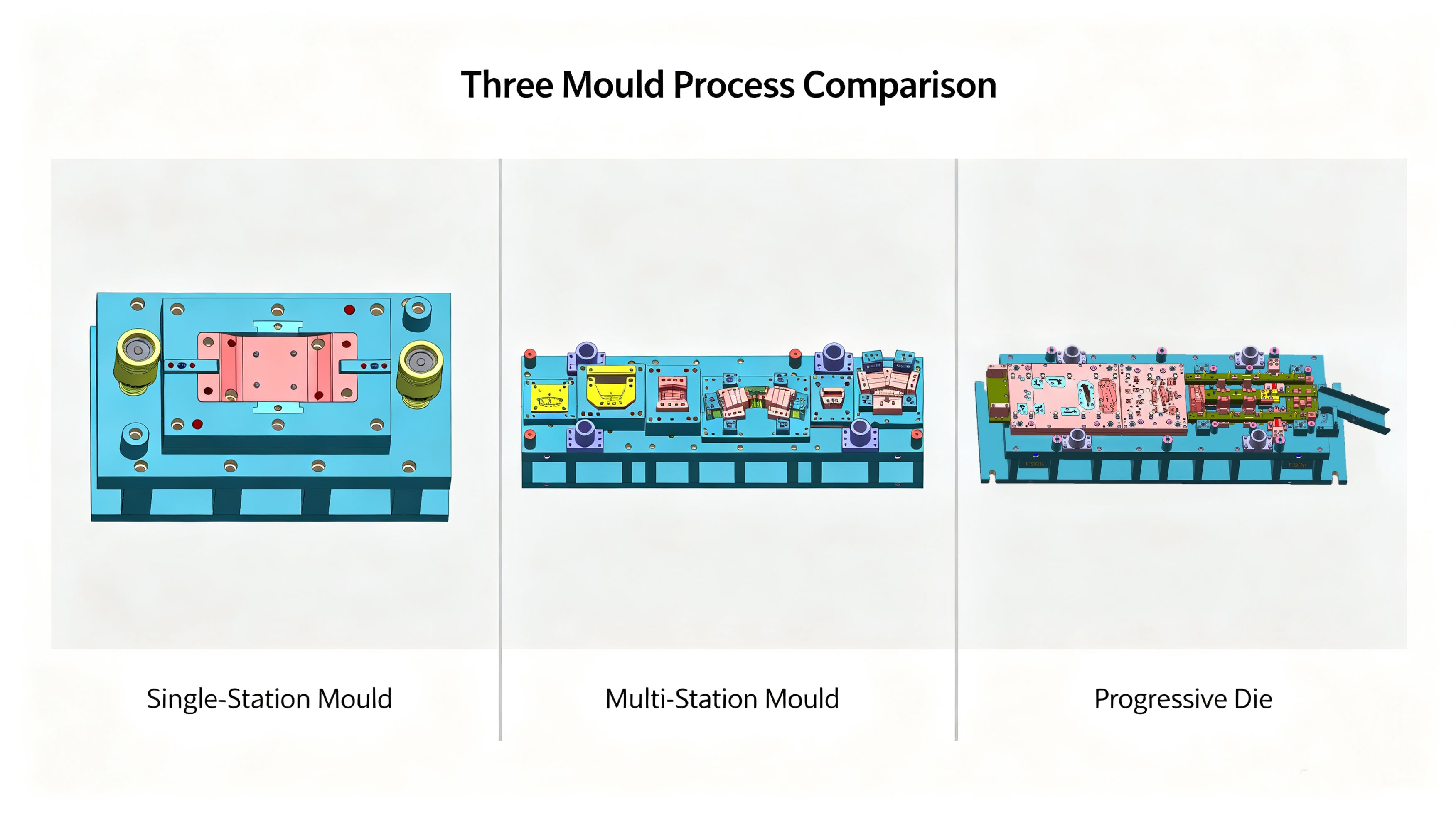
At its core, automotive metal stamping transforms flat sheet metal into three-dimensional parts through a series of forming operations: blanking, piercing, bending, drawing, and flanging. The industry relies on three primary process routes -- progressive die stamping, transfer die stamping, and single die stamping -- each optimized for different part sizes, production volumes, and complexity levels.
What distinguishes these processes is the fundamental question of how the workpiece moves through the forming sequence. Choosing the wrong process for a given part can double tooling costs, create production bottlenecks, or compromise dimensional accuracy.
Industry Reference: A modern automotive stamping facility typically operates 15-30 presses ranging from 40 to 1,000 tons, processes over 50 material grades from mild steel to advanced high-strength steel (AHSS) and aluminum, and produces millions of parts per month.
The real engineering challenge lies not in defining stamping but in matching the right process to the right part. That is what the remainder of this article addresses -- from the perspective of a manufacturer that has delivered over 1,000 stamping dies and produces 5 million stamped parts per month for global automotive Tier 1 clients. For a deeper look at production-scale capabilities, see our custom automotive stamping overview.
Three Core Stamping Processes for Automotive Parts
Every stamped automotive part begins with the same question: which process route is the right one? The answer depends on four variables -- annual volume, part dimensions, material thickness, and complexity. Below, we examine the three core stamping processes and their decision logic.
Progressive Die -- High Volume, Small-to-Medium Parts
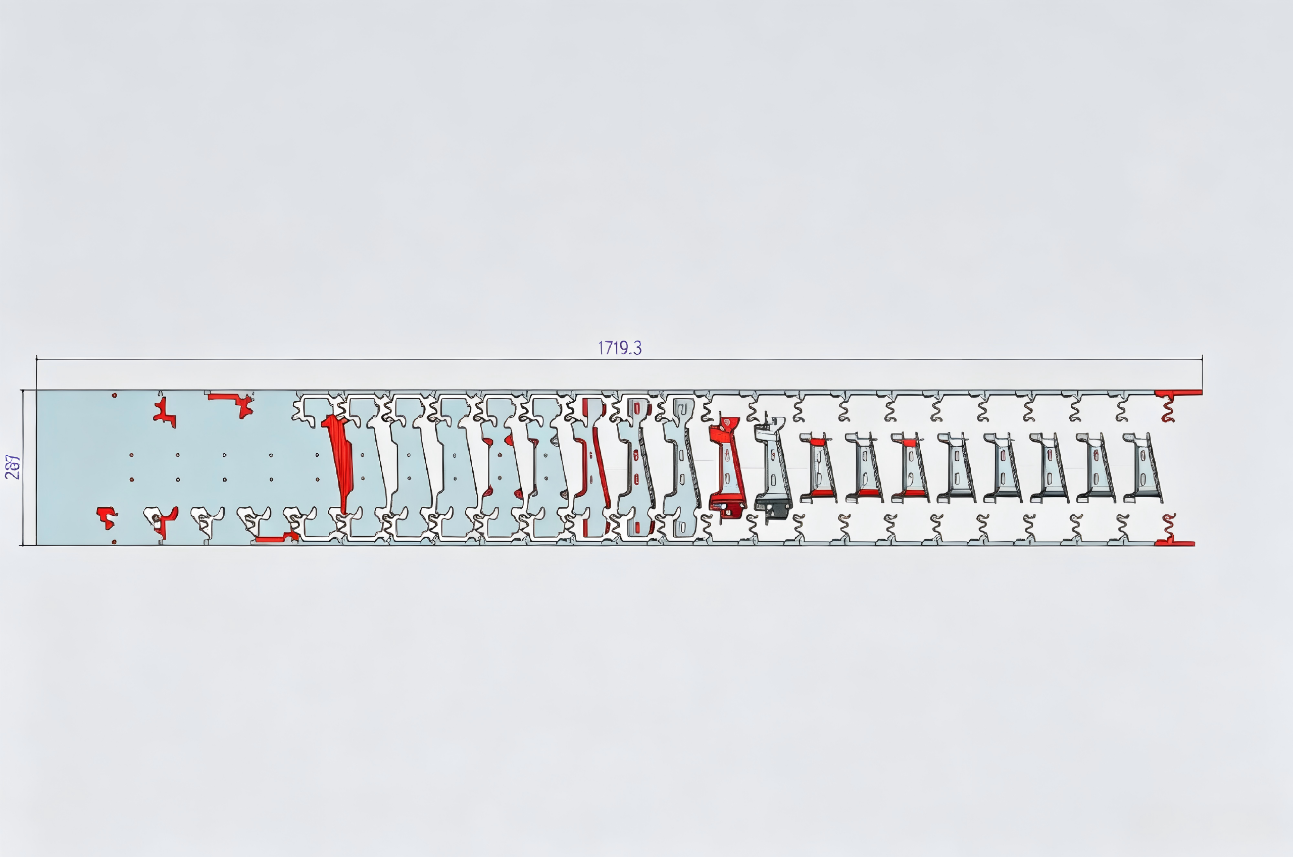
Progressive die stamping feeds a coil strip through a series of stations within a single die set. At each press stroke, every station performs one operation -- one station blanks, the next pierces, the next bends -- and by the final station, a complete part is ejected. The strip itself carries the workpiece from station to station, guided by pilot pins that maintain positioning accuracy within +-0.02 mm.
Key technical elements:
- Strip layout design determines material utilization, station sequencing, and overall die size -- often the single largest factor in per-part cost
- Pilot pins engage pre-pierced holes at each station to correct any strip positioning drift
- Lifters raise the strip between strokes so it can advance without dragging on die surfaces
- In-die sensors detect misfeeds, slug pulling, and part ejection failures in real time
Progressive dies excel at annual volumes above 50,000 pieces for small-to-medium parts (typically under 600 mm in strip width). Common automotive applications include brackets, connectors, clips, small structural reinforcements, and seat mechanism components. The process achieves the highest output rates -- 25 to 40 strokes per minute (SPM) is typical -- but the tooling investment is substantial, ranging from moderate for simple blanking dies to significant for complex forming dies with 12+ stations.
Manufacturer Reference: A full-service progressive die program -- from strip layout design through CAE forming simulation, die steel selection, machining, tryout, and PPAP submission -- typically takes 5-7 weeks for standard automotive projects, with first-pass approval rates exceeding 93% when CAE simulation is integrated into the design phase.
Transfer Die -- Large Structural Parts, Medium-to-High Volume
Transfer die stamping solves the fundamental limitation of progressive dies: the part must remain attached to the carrier strip. For large parts -- subframes, cross-members, longitudinal beams, control arms -- this is physically impossible because the blank dimensions exceed available coil widths and the part weight makes strip-based transfer impractical.
In a transfer die system, each station is an independent upper and lower die set. A mechanical transfer system -- typically servo-driven gripper rails or robotic arms -- picks up the blank or partially formed part at each station and moves it to the next. Because the workpiece is released and re-gripped between stations, there is no carrier strip, no width limitation, and each station can be designed, optimized, and maintained independently.
Transfer dies operate in the 20,000 to 200,000 pieces-per-year range on presses from 630 to 1,000 tons with 3-6 stations. The key advantage is flexibility: a single transfer press can run different part families by swapping die sets, and individual station dies can be replaced or reworked without affecting the entire system.
When to choose transfer die over progressive die:
- Part blank exceeds 600 mm in any dimension
- Part requires deep drawing that would distort a carrier strip
- Production volume does not justify the higher tooling cost of a large progressive die
- The part is a structural safety component requiring 100% in-process inspection at each station
For an example of a transfer die application at scale, see the subframe case study in Section 3 below.
Single Die -- The Right Choice for Low Volume, Oversized Parts, and Prototypes
Single die stamping is the most flexible and lowest-cost entry point into metal stamping. Each press stroke performs exactly one operation -- blank, pierce, bend, or form -- using a dedicated die. A complex part may require 3-8 single dies to complete all forming steps, with parts moved manually or by simple automation between presses.
Single dies are not a lesser process -- they are the optimal choice in specific scenarios where progressive or transfer tooling would be economically or physically impractical:
- Part dimensions exceed 600 mm -- beyond typical coil width limits for progressive tooling
- Annual volume below 20,000 pieces -- the unit-cost advantage of progressive tooling does not offset the higher upfront die investment
- Material thickness exceeds 6 mm -- thick-gauge forming requires press forces and die clearances that are difficult to achieve in multi-station progressive layouts
- Prototype and pre-production validation -- single dies enable process validation at low cost (2-4 week lead time) before committing to full progressive or transfer tooling
Industry Reference Value: Single die tooling costs typically range from 10% to 25% of an equivalent progressive die set. When paired with a strategic upgrade path -- where validated single-die process data directly informs the design of a subsequent progressive or transfer die -- the combined approach can reduce total program tooling costs while simultaneously de-risking the production ramp-up.
Process Selection Comparison
| Criteria | Progressive Die | Transfer Die | Single Die |
|---|---|---|---|
| Annual Volume | >50,000 pcs | 20,000-200,000 pcs | <20,000 pcs |
| Part Size | Small-to-medium (<600 mm strip width) | Medium-to-large (no width limit) | Any size |
| Material Thickness | 0.3-6.0 mm | 0.5-8.0 mm | 0.3-12.0 mm |
| Tooling Investment | High -- single die set with 8-20+ stations | Medium-high -- 3-6 independent die sets + transfer system | Low -- individual dies, 3-8 per part |
| Material Utilization | 60-75% (carrier strip scrap) | 75-85% (individual blank nesting) | Variable (manual or semi-auto nesting) |
| Typical Accuracy | +-0.05 mm | +-0.10 mm | +-0.15 mm |
| Best For | Brackets, connectors, clips, seat components | Subframes, cross-members, control arms, B-pillars | Prototypes, oversize panels, thick-gauge structural parts |
Note: Values are industry reference ranges. Actual project data varies with part geometry, material grade, and press capability.
For a deeper discussion on matching part requirements to manufacturing processes, refer to our guide on how to match part requirements with the right process.
Automotive Applications: What Process for Which Part
The choice of stamping process is ultimately driven by the part itself -- its size, material, structural function, and production volume. Below, we examine how these factors play out across three major automotive application categories, using real production examples.
Chassis & Structural Components
Chassis structural parts -- subframes, cross-members, longitudinal beams, and control arms -- present the most demanding stamping challenge in automotive manufacturing. These are large, thick-gauge parts (1.5-4.0 mm) made from high-strength steels such as DP600, DP800, and QSTE500TM, where springback control and weld assembly accuracy are the dominant engineering concerns.
The standard process route is transfer die stamping followed by robotic welding assembly. Transfer tooling is essential because blank dimensions for a typical front subframe exceed 800 mm in several directions -- far beyond progressive die strip width limits. After stamping, individual parts are welded into a complete assembly, often with 15-20 weld joints that must maintain positional accuracy within +-0.5 mm.
Production Case -- Front Subframe Assembly:
A European luxury SUV platform required a front subframe assembly consisting of 7 individual stampings joined by 17 MIG weld joints. The subframe -- which carries the engine, transmission, and front suspension -- is a collision load-path component, meaning dimensional accuracy directly affects crash performance. Annual volume: 80,000 vehicle sets.
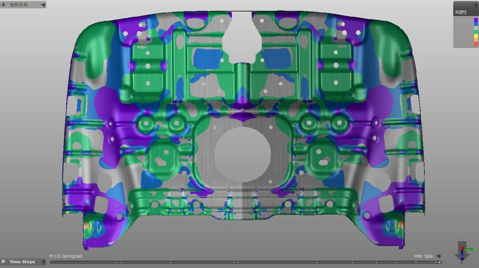
Before cutting any tool steel, the CAE engineering team performed forming simulation on all 7 parts. The simulation identified: a reinforcement bracket corner with thinning exceeding 25% (forming limit for QSTE500TM is approximately 28%) -- resolved by increasing the corner radius from R3.0 to R4.5; a draw flange area showing material accumulation (wrinkling risk) -- resolved by adding one draw bead and adjusting bead height; and a sidewall flange with predicted springback of 2.3 degrees -- compensated by reverse-offsetting the die cavity surface.
All 7 stamping dies were manufactured based on the CAE-corrected tooling data. First-article parts passed dimensional inspection without a single die rework iteration. The complete process -- 7 stampings + 17 welds -- was validated within the program timeline, and the subframe entered series production on schedule.
"The CAE simulation did not just predict problems -- it eliminated the trial-and-error phase entirely. Seven dies, first try, all within tolerance."
Body-in-White & Safety Components
Body structure parts -- B-pillar reinforcements, roof rails, side-impact beams, and seat cross-members -- are safety-critical components, often made from hot-formed boron steel (22MnB5) or ultra-high-strength cold-formed steels. The dominant engineering challenges are thinning control (to avoid cracking during forming) and springback compensation after hot stamping.
These parts typically run on transfer die systems, with hot stamping integrated into the press line for boron steel grades. Because a single B-pillar reinforcement can involve blanking, hot forming, trimming, and piercing across 4-5 stations, the transfer die architecture provides the necessary station independence.
Production Case -- B-Pillar Reinforcement:
A Japanese Tier 1 supplier was developing a B-pillar reinforcement in 22MnB5 (1.8 mm thickness) for a global mid-size sedan platform. The part had already entered the tooling phase with another die manufacturer -- without prior CAE simulation. The T1 (first trial) samples showed three problems: corner micro-cracking at two locations, wrinkling in a flange area, and springback angles of 2.1, 1.8, and 2.5 degrees across three critical sections -- well beyond the +-0.5 degree tolerance. After three rounds of die rework over six weeks, the issues persisted, and the SOP (start of production) milestone was at risk.
An independent CAE analysis was performed on the same part geometry. Within three working days, the simulation identified: corner thinning rates of 32% and 29% -- exceeding the 28% forming limit for 22MnB5 in cold condition, precisely matching the crack locations; material accumulation (15% thickness increase) in the flange area -- compression instability during flanging, matching the wrinkling pattern; and springback angles matching the measured values within 0.2 degrees, confirming the simulation accuracy.
The corrective actions -- increasing corner radii (validated with the structural engineering team to confirm no impact on crash performance), adding a pre-bend step to split the 90-degree flange into two 45-degree stages, and applying reverse compensation to the die surfaces -- were implemented before any further steel was cut. The revised tooling produced conforming parts on the first trial.
Suspension, Steering & Powertrain Components
This category spans precision parts -- shock absorber tubes, bushing shafts, control arm pins, steering column sleeves, and engine mount brackets. Unlike chassis structural parts where size and strength dominate, suspension and powertrain parts demand precision (inner diameters to IT7 grade, surface finishes to Ra 0.4 um) and, in many cases, fatigue strength under cyclic loading.
Production Case -- Shock Absorber Tubes (High-Volume Automated Line):
A top-5 global shock absorber Tier 1 supplier -- serving Volkswagen MQB and BMW CLAR platforms -- required an Asia-Pacific strategic partner for damper tube production. Annual volume: 2.4 million vehicle sets, equivalent to 7.2 million individual tubes per year (each set = 1 outer tube + 1 inner tube + 1 top mount sleeve).
The tube production line operates as a fully automated, 7-step process with zero operator intervention between raw material input and finished-part output: (1) Automatic cut-to-length -- 9 machines, cut tolerance +-0.1 mm; (2) Double-end chamfering -- 17 machines, both ends simultaneously; (3) Laser tube cutting for special geometries; (4) Knurling for press-fit interfaces; (5) Ultrasonic cleaning -- removing all cutting fluid and particulate residue; (6) 100% inline automated dimensional inspection -- 9 inspection units using infrared measurement, checking inner/outer diameter, roundness, and wall thickness on every single tube; (7) Packing and shipment.
The 100% inline inspection was the decisive factor in supplier selection. The previous supplier used statistical sampling with manual gauging -- a model that carries inherent missed-defect risk. The automated line eliminates this risk: if a tube fails any dimension check, it is physically diverted from the output stream before it can reach a shipping container.
Production Case -- Control Arm Bushing Shaft (Cold Heading Replaces Machining):
A Chinese Tier 1 chassis system supplier serving BYD and NIO needed 320,000 bushing shafts per year across four vehicle models. The shaft is a precision pin -- O16 mm shank with a O22 mm flanged head and spherical end -- made from 42CrMo alloy steel, requiring quench-and-temper to 900+ MPa tensile strength on the shank and HRC 58-62 on the head.
The original process machined the shaft from O25 mm bar stock via CNC turning -- removing 59% of the material as chips. At 320,000 pieces per year, this meant over 90 tonnes of steel wasted annually, with a per-piece machining cost driven by a 4.5-minute cycle time.
The alternative proposal: cold heading from O18 mm wire. The part geometry -- a slender shank (L/D ratio approximately 5:1), a flanged head, and a spherical end -- is well-suited to multi-station cold forming. The 4-station cold heading die produces a near-net-shape blank in under 3 seconds, with material utilization jumping from 41% to 94% (only head finishing and shank grinding remove material).
The three initial concerns -- higher die investment, fatigue performance of cold-headed vs. machined parts, and spherical-end accuracy -- were addressed with data: Die investment amortized to a negligible per-piece cost against the processing cost reduction; Uninterrupted grain flow in cold-headed parts (material fibers flow around the head contour rather than being cut through) provides superior fatigue resistance -- critical for a suspension component under cyclic bending loads; and spherical-end geometry is achieved through the cold heading die cavity and refined through secondary grinding, meeting the specified profile tolerance.
The conversion saved the customer over 90 tonnes of steel annually and reduced per-piece cost significantly. For more on cold heading technology, see our automotive cold heading capabilities. Related precision bushing applications are covered in our automotive metal bushings overview.
Application-Process Matching Reference
| Automotive Part | Recommended Process | Typical Material | Key Requirement |
|---|---|---|---|
| Front subframe | Transfer die + weld assembly | QSTE500TM / DP600 | Springback control + weld accuracy |
| B-pillar reinforcement | Transfer die + hot stamping | 22MnB5 | Thinning control + no micro-cracks |
| Shock absorber tube | Automated tube line | Low-carbon / alloy steel | ID IT7 + 100% inline inspection |
| Control arm bushing shaft | Cold heading + grinding | 42CrMo | Tensile 900+ MPa / HRC 58-62 |
| Small bracket / clip | Progressive die | Carbon steel / galvanized | Output >25 SPM / consistency |
| Prototype / thick-gauge panel | Single die | Various | Lead time 2-4 weeks / low cost |
Quality Control: The Full Inspection Chain Behind Automotive Stamping
Most articles on automotive stamping mention quality control in a single sentence -- usually "we follow IATF 16949 standards" -- and move on. In practice, quality assurance for stamped automotive parts is not a single checkpoint but a six-dimensional system that spans the entire production lifecycle, from incoming raw material to final shipment.
Quality Standards & Certification
IATF 16949 is the global quality management standard for automotive series production and service parts. Unlike generic ISO 9001, IATF 16949 imposes automotive-specific requirements: defect prevention, continuous improvement, and waste reduction throughout the supply chain. For a Tier 1 or Tier 2 automotive supplier, IATF 16949 certification is the minimum requirement to enter the sourcing process.
IATF 16949 certified (Certificate No. 0532672)
Beyond certification, the Production Part Approval Process (PPAP) is the gatekeeper between tooling completion and series production. PPAP requires the supplier to demonstrate -- with measured data, not promises -- that the production process can consistently produce parts meeting all dimensional, material, and performance specifications at the quoted production rate. For stamping specifically, PPAP submission includes: dimensional layout reports (CMM data for all drawing dimensions), material certifications, process capability studies (CPK data for critical characteristics), and a qualified laboratory scope.
Dimensional Inspection -- CMM & In-Process Measurement
Coordinate Measuring Machines (CMM) are the gold standard for stamped part dimensional verification. A CMM probes the part surface at hundreds of programmed points, comparing measured coordinates to the 3D CAD model. For automotive stamping, CMM inspection serves three distinct purposes:
- First-article inspection (FAI): Complete dimensional verification of the first parts from a new or modified die. Every drawing dimension is measured and recorded. FAI is a mandatory PPAP deliverable.
- In-process sampling: Periodic dimensional checks during production runs -- typically every 2-4 hours -- to detect process drift before it produces non-conforming parts
- Die wear monitoring: Tracking dimensional trends over the die's service life to predict when die components need replacement or sharpening
Industry Reference Value: Modern CMM systems achieve volumetric accuracy of 1.5 + L/350 um (where L is the measured length in mm). For a typical stamped part dimension of 200 mm, this translates to measurement uncertainty of approximately 2.1 um -- well within the tolerance band of precision automotive stampings.
SPC -- Statistical Process Control in High-Volume Stamping
SPC shifts quality assurance from detection ("find the bad parts") to prevention ("keep the process from making bad parts"). Rather than measuring every part or relying on end-of-line sampling, SPC monitors the process behavior itself using control charts and capability indices.
The most commonly reported capability index in automotive stamping is CPK -- the process capability index that accounts for both process variation and centering relative to specification limits:
- CPK >= 1.33: Process is capable -- expected defect rate below 63 parts per million (ppm). Typical minimum for automotive production.
- CPK >= 1.67: Process is well-centered and stable -- expected defect rate below 0.6 ppm. Required for safety-critical characteristics.
- CPK < 1.00: Process is not capable -- defect rate exceeds 2,700 ppm. Requires immediate corrective action.
For a stamping operation running 100,000 parts per month, the difference between CPK 1.00 and CPK 1.33 is approximately 257 potentially defective parts per month that either get caught (inspection cost) or get shipped (quality risk).
SPC implementation typically focuses on 3-8 critical-to-quality (CTQ) characteristics per part -- dimensions that directly affect fit, function, or downstream assembly. For a deeper discussion on tolerance strategy, see why manufacturing tolerances should be set early.
NDT & Functional Testing -- Beyond Dimensions
Dimensional conformance is necessary but not sufficient. Safety-critical stamped assemblies -- particularly welded subframes, suspension components, and seat structures -- require non-destructive testing (NDT) to verify internal integrity:
- Ultrasonic testing (UT): Detects internal weld defects -- porosity, lack of fusion, cracks -- by analyzing high-frequency sound wave reflections. Used on structural weld joints in chassis assemblies.
- Magnetic particle inspection (MPI): Reveals surface and near-surface cracks in ferromagnetic materials. Applied to stamping blank edges, formed corners, and weld heat-affected zones.
- Dye penetrant inspection (DPI): Detects surface-breaking defects in non-ferromagnetic materials (aluminum, stainless steel). Used on aluminum stampings and cosmetic Class-A surfaces.
Static and dynamic testing complete the quality picture. Static testing verifies material properties (tensile strength, hardness, chemical composition) on raw material samples and finished parts. Dynamic testing validates functional performance under cyclic load, answering the question that dimensional data alone cannot: "Will the part perform its intended function over the vehicle's service life?"
For practical guidance on designing parts that are inherently easier to inspect, see what makes a fabricated part easy to inspect.
| Inspection Type | What It Checks | Typical Equipment | When Applied |
|---|---|---|---|
| CMM Dimensional | All dimensions vs. CAD | Bridge/gantry CMM, laser scanner | First article, sampling, die wear tracking |
| SPC Process Control | Process stability & capability (CPK) | Control charts, SPC software | Continuous in-production monitoring |
| Static Testing | Material properties | UTM, spectrometer, hardness tester | Incoming material, heat treat verification |
| Dynamic Testing | Functional performance under load | Servo-hydraulic test rigs, fatigue testers | Design validation, PPAP, requalification |
| NDT | Internal & surface defects | UT flaw detector, MPI bench, DPI kit | Weld joints, safety-critical formed areas |
| Mold Tryout & FAI | Die performance & first-part conformance | CMM, surface profilometer | New die qualification, modification verification |
For a comprehensive overview of our quality system, visit our IATF 16949 quality assurance page.
Die Engineering: CAE Simulation Before Metal Cutting
The most expensive mistake in stamping is discovering a forming problem after the die has been machined. Traditional die development -- design, machine, tryout, find problems, rework, try again -- can consume weeks of schedule and significant budget in iterative rework loops. The modern approach inverts this sequence: simulate everything before cutting anything.
Why Die Engineering Happens Before the First Cut
CAE (Computer-Aided Engineering) forming simulation has become the standard front-end for automotive stamping die development, for a simple economic reason: the cost of fixing a problem in simulation is near zero; the cost of fixing it in hardened tool steel is measured in weeks of downtime and significant rework expense per iteration.
The simulation workflow typically follows three stages: (1) Formability analysis -- can this part geometry be formed from the specified material without cracking or wrinkling? (2) Springback prediction -- after forming and unloading, how much will the part elastically recover, and what reverse compensation must be applied to the die surfaces? (3) Process optimization -- can the blank shape be modified to improve material utilization? Can the draw bead layout be adjusted to balance material flow?
The output is a Technical Review (TR) report -- typically 40-60 pages covering formability, springback, blank development, and process recommendations -- that the engineering team reviews before approving die manufacturing.
What CAE Simulation Actually Delivers
Returning to the B-pillar reinforcement case: the CAE simulation identified the exact locations where cracking and wrinkling would occur, quantified the springback angles at each critical section, and provided the specific corrective actions that resolved all three issues in a single iteration. The simulation accuracy -- springback predictions within 0.2 degrees of measured values -- is what makes CAE a reliable engineering tool rather than a visualization gimmick.
For the front subframe case, CAE simulation was performed on all 7 stampings before any die steel was ordered. All 7 dies passed first-article dimensional inspection -- a result that would be statistically improbable without simulation-guided tooling design. For more on design simplification, see how to simplify complex metal part structures.
From Single Die Prototype to Progressive Die Production
One of the most underutilized strategies in stamping die engineering is the sequential tooling path: validate the forming process with low-cost single dies, then use the validated process data -- forming forces, material flow patterns, springback measurements -- to design the full progressive or transfer die set.
This approach is particularly valuable when the part design is not yet frozen, the annual volume ramp-up is gradual, or the material behavior is not fully characterized. The key enabler is data continuity: the forming parameters, springback measurements, and trim line developments from the single-die phase are not discarded when moving to production tooling -- they become the engineering basis for the progressive or transfer die design. For die design and manufacturing capabilities, visit our automotive stamping die manufacturing page.
SHAOYI CAE forming simulation result showing a color-mapped thinning distribution on a stamped automotive part
"The simulation-to-tooling feedback loop is what separates engineering-driven die development from trial-and-error. When the single-die data flows directly into the progressive die design, you eliminate the learning curve -- and the rework budget -- from every new program."
Frequently Asked Questions
What is automotive metal stamping?
Automotive metal stamping is a cold-forming manufacturing process that transforms flat sheet metal into three-dimensional vehicle components using a stamping press and custom-designed tooling (dies). The process encompasses multiple operations -- blanking, piercing, bending, drawing, flanging, and coining -- performed sequentially to produce parts ranging from small brackets to large chassis subframes. It is the dominant metal forming method in automotive manufacturing due to its speed, repeatability, and material efficiency at production volumes.
What are the different types of stamping processes used in automotive manufacturing?
The three primary stamping processes are progressive die (coil-fed, multi-station within a single die set, best for high-volume small-to-medium parts), transfer die (individual stations with robotic part transfer, best for large structural parts at medium-to-high volume), and single die (one operation per press stroke, best for low volume, oversized parts, and prototypes). Each process optimizes for a different combination of part size, annual volume, and tooling investment.
Progressive die vs transfer die stamping -- which is better for automotive parts?
Neither process is universally better -- the choice depends on the part. Progressive dies deliver the highest output rates (25-40 SPM) and tightest tolerances (+-0.05 mm) for parts that fit within coil strip width limits (typically under 600 mm). Transfer dies handle parts too large for coil-fed tooling -- subframes, cross-members, control arms -- and provide the flexibility to independently maintain or replace individual station dies. A manufacturer offering both processes can select the optimal route for each part rather than forcing every part through a single process type.
What materials are commonly used in automotive stamping?
Automotive stamping processes a wide range of materials, from low-carbon steel (DC01-DC06 grades) for general brackets and enclosures to advanced high-strength steels (DP600/DP800, QP980, MS1500, TRIP steels) for structural and safety components. Hot-formed boron steel (22MnB5) is used for occupant-cage safety parts. Galvanized steels (GI, GA coatings) provide corrosion protection for body panels. Aluminum alloys (5000 and 6000 series) are increasingly specified for lightweighting in electric vehicles. A full-service stamping supplier typically maintains capability across 50+ material grades.
What tolerances can automotive metal stamping achieve?
Typical dimensional tolerances for automotive stampings range from +-0.05 mm for progressive die parts (small brackets, connectors) to +-0.15 mm for single die parts (large panels, thick-gauge structural components). Transfer die parts typically fall in the +-0.10 mm range. These values assume proper die condition, consistent material properties, and stable press parameters. Tighter tolerances are achievable but increase tooling cost and process control requirements.
How to choose a metal stamping supplier for automotive parts?
Evaluate potential suppliers across five dimensions: (1) Process range -- can they offer progressive, transfer, and single die to select the optimal route for each part? (2) Engineering capability -- do they perform CAE forming simulation in-house? (3) Quality infrastructure -- do they hold IATF 16949 certification and operate a complete inspection chain (CMM, SPC, NDT, functional testing)? (4) Volume scalability -- can they support your program from prototype through series production? (5) Material coverage -- do they have documented experience with the specific material grades your parts require? A supplier that can answer all five questions with data -- not just assurances -- is equipped to support automotive production programs. For more on Shaoyi's specific capabilities, see our custom automotive stamping overview.