 Small batches, high standards. Our rapid prototyping service makes validation faster and easier —

Stamping Die Components Exposed: What Causes Costly Failures
Understanding Stamping Die Components and Their Critical Functions
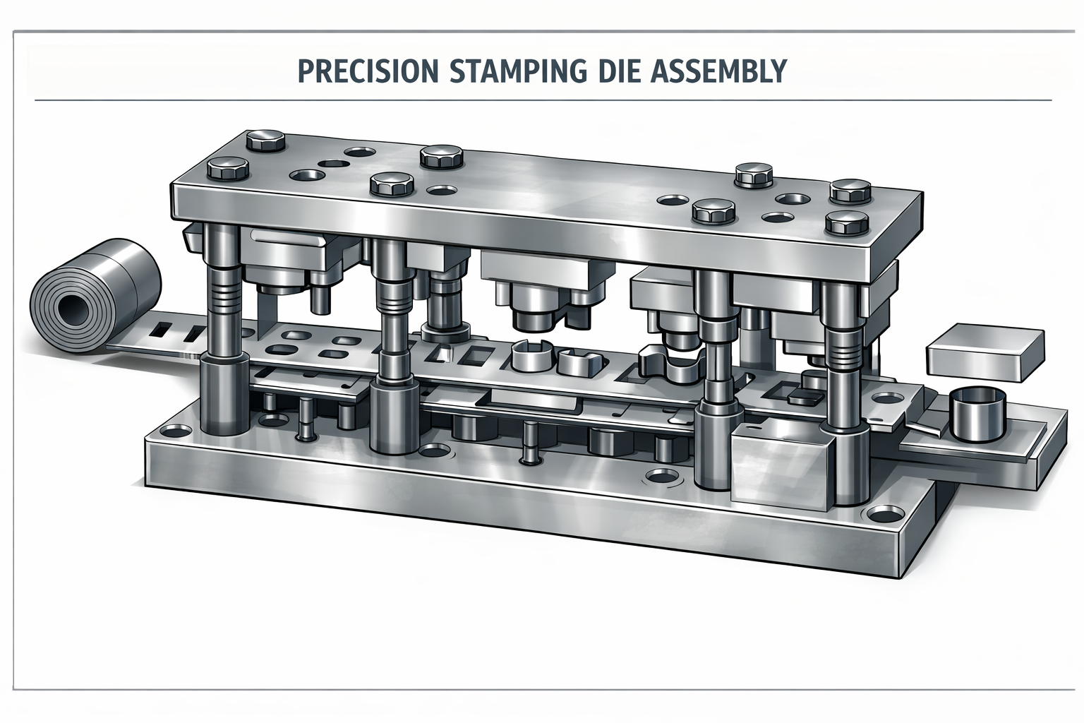
What transforms a flat sheet of metal into a precisely formed automotive bracket or electronic enclosure? The answer lies in stamping die components—the specialized tooling elements that work together to cut, bend, and shape metal with remarkable accuracy. These components form the backbone of metal forming operations across industries, from automotive manufacturing to consumer electronics production.
So, what is a die in manufacturing? Simply put, a die is a specialized tool used in manufacturing to cut or shape material using a press. When you ask what are dies in the context of metal stamping, you're looking at complex assemblies containing dozens of individual components, each engineered for a specific purpose within the forming process.
The Building Blocks of Metal Forming Operations
Stamping die components function as an integrated system rather than isolated parts. Picture a symphony orchestra—each instrument plays its role, but the magic happens when they work together seamlessly. Similarly, die components including punches, die buttons, guide posts, and stripper plates must operate in perfect coordination to transform raw material into finished parts.
Metal stamping components fall into several functional categories: structural elements that provide the framework, cutting components that pierce and blank material, guiding systems that ensure alignment, and material handling parts that control strip movement. Understanding what is die manufacturing helps you appreciate how these elements come together during the tooling construction process.
Why Component Quality Determines Stamping Success
The relationship between component quality and production outcomes is direct and measurable. Worn cutting edges produce burrs. Misaligned guides cause punch breakage. Inadequate structural rigidity leads to dimensional variation. Each component failure cascades into quality issues, unplanned downtime, and increased costs.
Component precision at the micron level translates directly into part quality at the production level—a die built with inferior components will never produce superior parts, regardless of press capability or operator skill.
This article takes you beyond basic component identification. You'll explore the complete lifecycle approach—from intelligent material selection and proper specification through effective maintenance strategies. Whether you're an engineer specifying new tooling or a buyer evaluating supplier capabilities, understanding these die components empowers better decisions about your tooling investments. The sections ahead cover structural foundations, cutting elements, alignment systems, material handling, steel selection, wear analysis, maintenance protocols, and application-specific selection guidance.
Structural Foundation Components That Support Die Operations
Imagine building a house on a weak foundation—no matter how beautiful the structure above, cracks will eventually appear. The same principle applies to stamping die components. The structural foundation elements determine whether your die assembly delivers consistent, accurate parts across thousands or millions of cycles. Without robust structural components, even the most precisely machined cutting elements will fail to perform.
The die assembly framework consists of three primary structural categories: die shoes that bear the load, die plates that provide mounting surfaces, and complete die sets that combine these elements with alignment systems. Let's examine each component and understand why material selection and hardness specifications matter so much.
Die Shoes and Their Load-Bearing Role
Die shoes serve as the primary structural backbone of any stamping operation. Think of them as the chassis of a vehicle—they support everything else and absorb tremendous forces during each press stroke. A typical set of die includes both upper and lower die shoes that mount directly to the press ram and bolster plate respectively.
The upper die shoe attaches to the press ram and carries all the punch components downward during the forming stroke. Meanwhile, the lower die shoe secures to the press bolster and supports the die blocks, buttons, and material handling components. Together, these shoes must withstand compressive forces that can exceed hundreds of tons while maintaining flatness tolerances measured in thousandths of an inch.
What makes a die shoe effective? Three critical factors come into play:
- Adequate thickness to resist deflection under load—undersized shoes flex during stamping, causing misalignment and accelerated wear
- Proper material selection based on production volume and force requirements
- Precision machining of mounting surfaces to ensure parallelism between upper and lower assemblies
For high-volume automotive applications, die shoes typically feature hardened tool steel construction. Lower-volume operations may use pre-hardened steel or even aluminum for reduced weight and faster press speeds.
Die Plates as Precision Mounting Surfaces
While die shoes provide the structural framework, die plates offer the precision mounting surfaces where cutting and forming components attach. A die plate sits atop the die shoe and provides a hardened, flat surface machined to exact tolerances for component installation.
Why not mount components directly to the die shoe? The answer involves both practicality and economics. Die plates can be replaced when worn without scrapping the entire shoe. They also allow for localized hardening treatments that would be impractical across an entire shoe surface. When assembling a die, manufacturers often use multiple die plates within a single assembly, each supporting different functional areas.
The assembly die configuration becomes particularly important in progressive dies where multiple stations perform sequential operations. Each station may require different plate thicknesses or hardness levels based on the specific forming forces involved. Proper plate selection ensures that mounting surfaces remain stable and true throughout the production run.
Die Sets: Pre-Assembled Alignment Solutions
A complete set of die typically arrives as a pre-assembled unit combining upper and lower shoes with guide posts and bushings already installed. These die sets offer several advantages over building assemblies from individual components:
- Factory-guaranteed alignment between upper and lower shoes
- Reduced assembly time and setup complexity
- Consistent quality from standardized manufacturing processes
- Interchangeability for backup tooling strategies
Die sets come in various configurations—two-post, four-post, and diagonal arrangements—each suited to different die sizes and alignment requirements. The guide posts and bushings maintain precise registration between upper and lower assemblies throughout millions of press cycles.
Material Specifications for Structural Components
Selecting the right materials for structural components directly impacts tool life and part quality. The following table summarizes common material choices, their applications, and required hardness levels:
| Component Type | Common Materials | Hardness Range (HRC) | Typical Applications |
|---|---|---|---|
| Die Shoes (Standard) | A2 Tool Steel, 4140 Steel | 28-32 HRC | General production, medium volumes |
| Die Shoes (Heavy Duty) | D2 Tool Steel, S7 Tool Steel | 54-58 HRC | High-tonnage applications, long runs |
| Die Plates | A2, D2 Tool Steel | 58-62 HRC | Component mounting surfaces |
| Backing Plates | A2 Tool Steel | 45-50 HRC | Punch support, load distribution |
| Die Sets (Economy) | Cast Iron, Aluminum | N/A (as-cast) | Prototype work, short runs |
Notice that cutting and forming components require significantly higher hardness than structural elements. This graduated approach balances wear resistance where needed with toughness and machinability for the supporting framework.
Proper structural component selection prevents the deflection and misalignment that plague poorly designed dies. When shoes flex under load, punch-to-die clearances change dynamically during each stroke. This variation produces inconsistent edge quality, accelerates component wear, and ultimately leads to the costly failures that shut down production lines. Investing in appropriately specified structural components pays dividends throughout the tool's service life—and sets the stage for the cutting elements we'll examine next.
Punch and Die Cutting Elements That Shape Your Parts
Now that you understand the structural foundation, let's explore the components that actually do the work. Die punches and their mating die openings are the cutting edges where metal meets force—and where precision truly matters. These elements directly contact your material, experiencing tremendous stress with every press stroke. Getting them right determines whether you produce clean parts or scrap.
Consider this: cutting a 10-inch-diameter blank from 0.100-inch-thick mild steel requires approximately 78,000 pounds of pressure. That's the force these components must withstand—repeatedly, reliably, and without failure. Understanding how sheet metal punch and die systems work together helps you specify tooling that survives this demanding environment.
Punch Geometry and Its Impact on Cut Quality
When you examine metal punches and dies closely, you'll notice that punch geometry varies significantly based on application. Three primary punch types handle most stamping operations:
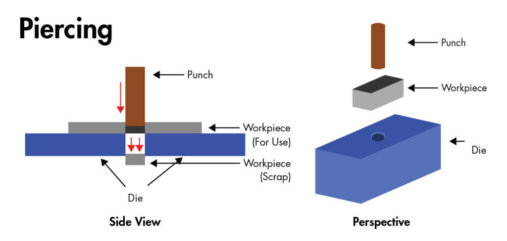
- Piercing punches create holes in the material, with the punched slug becoming scrap. The punch head mounts into a retainer while the cutting end features sharp edges matched to the desired hole shape.
- Blanking punches work opposite to piercing—the cut piece becomes your finished part while the surrounding material is scrap. These punches require extremely tight tolerances since they define your final product dimensions.
- Forming punches don't cut at all. Instead, they bend, draw, or otherwise shape material without separating it. These typically feature radiused edges rather than sharp cutting surfaces.
Here's something many engineers miss: the punch doesn't solely determine hole size. While it's common to assume a 0.500-inch punch produces a 0.500-inch hole, altering the clearance between punch and die button actually affects hole dimensions. Insufficient clearance causes metal to compress before cutting, gripping the punch sides and creating a hole slightly smaller than the punch diameter.
What about punch geometry around corners? If you're piercing square or rectangular holes, you'll notice corners break down first. Why? These areas experience the highest cutting loads because compressive forces concentrate at small radial features. A practical solution: increase clearance in corners to approximately 1.5 times the normal clearance, or avoid dead-sharp corners whenever possible.
Die Button Selection for Extended Tool Life
A button die—sometimes called a die insert or matrix—is the replaceable component that receives the punch and defines the cutting edge on the material's exit side. Think of sheet metal punch dies as a matched pair: the punch enters from above, shearing the material against the button's hardened edge below.
Why use replaceable die buttons instead of machining openings directly into the die plate? Several practical reasons:
- Buttons can be replaced individually when worn, avoiding costly die plate replacement
- Standard button sizes allow inventory stocking for quick maintenance turnarounds
- Premium button materials (carbide, for example) can be used economically in high-wear areas
- Precision grinding of small buttons is more practical than reworking entire plates
Die cut punch and button combinations must be carefully matched. The button's bore diameter exceeds the punch diameter by a specific clearance amount—and getting this relationship right is critical to your success.
The Critical Punch-to-Die Clearance Relationship
Clearance is the distance between the punch's cutting edge and the die button's cutting edge. This gap represents the optimal space required to shear material cleanly rather than tearing or crushing it. According to MISUMI's engineering guidelines, recommended clearance is expressed as a percentage per side—meaning this gap must exist on each edge of the cutting surface.
The standard guideline suggests 10% of material thickness per side as a starting point. However, modern manufacturing research indicates that using 11-20% clearance may considerably reduce tooling strain and increase operational life. The actual optimal clearance depends on multiple factors.
Factors affecting clearance selection include:
- Material type: Harder, higher-strength materials like stainless steel require increased clearance (around 13% per side), while softer metals like aluminum need smaller clearances
- Material thickness: Thicker workpieces require proportionally more clearance since the percentage is calculated against thickness
- Desired edge quality: Tighter clearances produce cleaner cuts but accelerate wear; applications requiring fine-blanking quality may use clearances as low as 0.5% per side
- Tool life requirements: Higher clearances reduce tooling strain, extending component life at some sacrifice to edge finish
- Punch geometry: Smaller punches and features with tight radii require more clearance to compensate for concentrated forces
What happens when clearance is wrong? Insufficient clearance causes the metal to compress and bulge away from the punch before cutting occurs. After the slug separates, the material grips the punch sides, dramatically increasing stripping force and accelerating edge breakdown. The result: premature punch failure, excessive burrs on parts, and potential safety hazards from fractured tooling.
Excessive clearance creates different problems—rough, torn edges rather than clean shear surfaces, plus increased burr height on the die side of the cut. Neither extreme produces acceptable parts.
Calculating Your Clearance Requirements
Once you've determined the appropriate clearance percentage for your application, calculating the actual per-side clearance is straightforward:
Clearance per side = Material thickness × Clearance percentage
For example, piercing 0.060-inch mild steel at 10% clearance per side requires 0.006-inch clearance on each side of the punch. The die button bore diameter would be the punch diameter plus twice this value (0.012 inches total clearance).
Proper clearance delivers multiple benefits: clean cuts with minimal burrs reduce secondary hand-processing time, optimized tool life reduces replacement costs and downtime, and lower cutting forces decrease press energy consumption. These cutting components work in harmony with the alignment systems covered next—because even perfectly specified punches and buttons will fail if they can't maintain precise registration throughout each stroke.
Guiding and Alignment Systems for Precision Registration
You've specified the perfect punch and die button combination with optimal clearance. But here's the challenge: that precision means nothing if the punch can't find the die opening accurately—every single time. This is where guiding and alignment components become essential. These tooling components maintain the precise relationship between upper and lower die assemblies throughout millions of press cycles.
Understanding tool and die meaning goes beyond just cutting elements. The "tool" encompasses the complete system including alignment mechanisms that ensure repeatable accuracy. Without proper guidance, even a dies set built with premium materials will produce inconsistent parts and suffer premature failure.
Guide Posts and Bushings for Repeatable Alignment
Guide posts—sometimes called leader pins or guide pillars—work together with guide bushings to align upper and lower die shoes precisely. According to industry guidelines from Dynamic Die Supply, these cylinder-shaped pins are made from hardened tool steel and precision-ground often within 0.0001 inch. That's about one-tenth the thickness of a human hair.
Here's something critical to understand: guide pins are not intended to compensate for a poorly maintained or sloppy press. The press must be independently guided with precision. Trying to fix press alignment problems by oversizing guide components leads to accelerated wear and eventual failure.
Two basic guide pin types serve different die tooling applications:
Friction pins (plain bearing pins) are slightly smaller than the guide bushing's inside diameter—typically about 0.0005 inch smaller. These pins offer several characteristics:
- Lower initial cost compared to ball bearing alternatives
- Better performance when significant side thrust is expected during forming
- Bushings lined with aluminum-bronze, often containing graphite plugs to reduce friction
- Require high-pressure grease lubrication
- Make die separation more difficult, especially on larger tools
One practical consideration: separating dies with friction pins requires careful technique. The upper and lower shoes must remain parallel during separation to avoid bending guide pins. Larger dies often require a hydraulic die separator to assist with this process.
Ball bearing pins (ultraprecision guide pins) represent the more popular choice for modern die tooling. These pins ride on ball bearings contained in a special aluminum cage that permits rotation without bearing loss. What makes them advantageous?
- Reduced friction allows faster press speeds without excessive heat generation
- Easy die separation for maintenance access
- Greater manufacturing accuracy—the pin and bearing assembly is approximately 0.0002 inch larger than the bushing bore, creating what manufacturers call "negative slop"
- Ideal for high-speed stamping operations
Important maintenance note: unlike friction pins, ball bearing guide pins should never be greased. Lubricate them with light oil only—grease can contaminate the ball cage and actually increase friction.
Heel Blocks and Their Role in Lateral Force Management
While guide posts handle vertical alignment, heel blocks address a different challenge: lateral forces generated during forming operations. According to The Fabricator's die basics guide, heel blocks are precision-machined steel blocks that are screwed, doweled, and often welded to both upper and lower die shoes.
Why are heel blocks necessary? During wipe bending, drawing, and other forming operations, the material resists deformation and pushes back against tooling. This side thrust can deflect guide pins if the force is substantial or one-directional. Deflected guides cause misalignment of critical cutting and forming components—exactly what you're trying to avoid.
Heel blocks contain wear plates made from dissimilar metals. Here's a crucial detail: using two opposing plates made of the same metal type creates high friction, heat, and eventually galling (cold welding) of the wear surfaces. The standard approach uses steel heel plates on one shoe with aluminum-bronze wear plates on the opposing shoe.
For tools running in presses of 400 tons or larger, Marwood's die design guidelines recommend corner heeling blocks to increase stability. Any die with "off balance" forming operations should also incorporate heeling to prevent lateral movement during the press stroke.
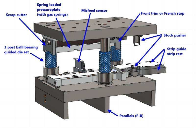
Stripper Plates: Dual-Function Alignment Components
Stripper plates serve two essential purposes in stamping operations. First, they guide punches during the cutting stroke, maintaining alignment as the punch enters the die button. Second, they strip—or remove—material from the punch body during the return stroke.
When metal is cut, it naturally collapses around the punch shank. This gripping action is especially pronounced during piercing operations. The spring-loaded stripper plate surrounds the cutting punches and mounts to the upper die shoe. As the punch withdraws from the material, the stripper holds the workpiece flush against the lower die section, allowing clean punch extraction.
Modern stripper designs incorporate milled windows that allow access to ball-lock punches and pilots without removing the entire plate. These windows should be machined with approximately 0.003-inch clearance to their pocket for easy removal during maintenance. Strippers on all piercing and cutting punches must be mechanically spring-loaded to ensure consistent material control.
Alignment Verification During Die Setup
Understanding tool and die definition includes recognizing that proper setup is as important as proper design. Before running production, verify alignment systematically:
- Inspect guide components visually for wear, scoring, or damage before mounting the die in the press
- Check guide pin fit by hand—pins should slide smoothly without binding or excessive play
- Verify heel block clearances and confirm wear plates show no signs of galling or excessive wear patterns
- Confirm stripper travel and spring pressure meet specifications for the material being processed
- Run a slow-speed test cycle observing punch entry into die buttons for any indication of misalignment
- Check first-off parts for burr location and edge quality as indicators of proper punch-to-die registration
- Monitor running alignment periodically, especially when temperature stabilizes after initial production cycles
When Worn Guides Cause Part Quality Problems
How do you know when guide components need attention? The symptoms often appear in your parts before you notice visible wear on the tooling:
- Inconsistent burr location: Burrs that shift position around hole perimeters indicate guide play allowing punch drift
- Increased punch breakage: When guides wear, punches contact die buttons off-center, creating side loading that fractures cutting edges
- Dimensional variation: Parts measuring differently from one side to another suggest alignment drift during the stroke
- Unusual noise or vibration: Loose guides create audible rattling or hammering as components contact improperly
- Scoring on punch bodies: Visible wear lines indicate the punch is rubbing against stripper openings due to misalignment
Addressing guide wear promptly prevents cascading failures. A worn bushing costs far less to replace than a broken punch—and far less than the production downtime and scrap associated with running misaligned dies. With alignment systems properly specified and maintained, your material handling components can do their job effectively, which we'll examine next.
Material Handling Components for Reliable Strip Control
Your guides are aligned, your punches are sharp, and your clearances are perfect. But here's a question: how does the material know where to go? In progressive stamping dies, the strip must advance precisely from station to station—sometimes dozens of times—before a finished part emerges. Material handling components make this choreography possible, and when they fail, the consequences range from scrap parts to catastrophic die damage.
Think about what happens during each press cycle. The strip feeds forward, stops at exactly the right position, gets pierced or formed, then moves again. Metal stamping dies rely on a family of specialized components to control this movement with repeatability measured in thousandths of an inch. Understanding these elements helps you diagnose feeding problems and prevent the misfeeds that cause costly downtime.
Pilot Pins for Accurate Strip Positioning
Pilots are precision-ground pins that enter previously pierced holes in the strip, locating it accurately for each subsequent operation. While stock guides get material close to position, pilots provide the final, precise registration that ensures every punch hits its target.
How do pilots work? During the press downstroke, pilot pins—typically featuring a bullet-nose or tapered tip—enter holes pierced at an earlier station. As the pilot fully engages, it centers the strip before cutting or forming operations begin. The pilot hole diameter is slightly larger than the pilot body, allowing entry while still constraining strip position.
Here's a critical timing consideration: the coil feeder must release the strip before pilots fully engage. According to The Fabricator's analysis of strip feeding, the feed rollers must unclamp the strip before full pilot entry. However, releasing too early allows the weight of the take-up loop to pull the strip out of position. The feed release must be timed so that the bullet nose of the pilot has entered the strip before the rollers open completely.
What happens when pilot timing is wrong? Improper feed release setup causes:
- Misfeed conditions requiring manual intervention
- Pilot hole elongation in the strip
- Bent, broken, or galled pilots
- Poor location and gauging of finished parts
For types of stamping dies that perform deep drawing, pilot timing becomes even more critical. Deep-drawn parts require substantial vertical lift to feed forward, and the strip must remain unclamped throughout this vertical travel.
Stock Guides and Lifters for Smooth Material Flow
Before pilots can locate the strip precisely, stock guides must deliver it to approximately the right position. These guides—rails mounted to the lower die shoe—constrain the strip's lateral movement as it advances through the die.
A common mistake? Setting stock guides too tightly against the strip edge. Remember that the function of guide rails is to guide the strip to a position where pilots can locate it—not to provide final positioning themselves. Because strip width and camber vary, overly tight guides create binding, buckling, and feeding failures.
Several stop mechanisms control strip advancement:
- Finger stops are spring-loaded pins that catch the strip edge, halting forward motion at predetermined progression distances
- Automatic stops use the press stroke itself to time advancement, retracting during the downstroke and engaging on the return
- Positive stops contact the strip's leading edge, providing a fixed reference for each progression
Lifters serve a different purpose—they raise the strip off the die surface between press strokes, creating clearance for forward feeding. Without lifters, friction between the strip and lower die components would impede advancement. In deep-draw applications, lifters must raise the strip enough to clear formed features before the next feed cycle.
A die is used to transform flat stock into complex shapes, but only if material flows smoothly between stations. Lifter height must match the vertical travel required—too little lift causes strip dragging, while excessive lift can interfere with pilot entry timing.
Understanding Bypass Notches and Their Critical Function
Ever wonder how pilots enter and exit previously pierced holes without tearing the strip? The purpose of bypass notches in stamping dies is to provide clearance for pilot pins as the strip moves forward. These small notches—cut into the strip's edge or internal carrier—allow pilots to slide past material that would otherwise block their path.
When a pilot enters a hole, the strip is stationary. But during feeding, the strip advances while pilots remain in their upper position. Without bypass notches, the strip would jam against pilot pins during this forward movement. The bypass notches in sheet metal stamping dies purpose is essentially creating escape routes that prevent interference during strip progression.
Bypass notch design requires careful consideration of pilot diameter, strip advancement distance, and the geometry of adjacent features. Undersized notches still cause interference, while oversized notches waste material and may weaken the strip's carrier section.
Common Material Handling Problems and Their Causes
When feeding problems occur, systematic troubleshooting identifies the responsible components. Here are frequent issues and their typical component-related causes:
- Strip buckling during feed: Feed line height misaligned with die level; stock guides set too tight; excessive friction from worn lifters
- Inconsistent progression distance: Worn finger stops; incorrect feed release timing; pilot holes not engaging properly
- Strip pulling to one side: Coil camber exceeding guide tolerance; uneven lifter heights; asymmetric pilot placement
- Pilot hole elongation: Feed release occurring after pilot entry; excessive strip tension from take-up loop; worn pilot tips
- Misfeed causing die crashes: Broken or missing lifters; contamination blocking stock guides; pilots sheared from prior misfeed
- Scrap not ejecting properly: Blocked slug openings; insufficient die clearance; vacuum conditions trapping slugs
Each of these symptoms points toward specific components. Addressing root causes—rather than repeatedly clearing jams—prevents the die damage that transforms a minor feeding issue into a major repair project.
Preventing Misfeed-Related Die Damage
Proper material handling does more than produce good parts—it protects your investment in the die itself. When strips misfeed, punches may hit at incorrect locations, striking hardened die steel instead of material. The result? Broken punches, damaged die buttons, and potential harm to structural components.
Several practices minimize misfeed risk:
- Verify feed line height matches die requirements before each run
- Confirm pilot release timing whenever changing material thickness or type
- Inspect lifters for wear and proper spring tension during routine maintenance
- Keep stock guides clean and free of slug fragments or lubricant buildup
- Monitor strip quality for excessive camber that exceeds guide tolerance
Progressive die stamping involves complex interactions between feeding equipment and die components. When these systems work together properly, material flows smoothly from coil to finished part. When they don't, the resulting failures can damage components throughout the die assembly—making material handling a critical focus area for anyone responsible for stamping operations. Next, we'll examine how tool steel selection affects the performance and longevity of all these components.
Tool Steel Selection and Material Specifications
You've learned how stamping die components work together—from structural foundations to cutting elements and alignment systems. But here's the question that determines whether those components last for thousands of cycles or millions: what are they made of? The die tool material you specify influences everything from initial machining costs to long-term maintenance requirements and ultimate failure mode.
Think of tool steel selection like choosing the right athlete for a specific sport. A marathon runner and a weightlifter both need strength and endurance, but in completely different proportions. Similarly, a piercing punch demands extreme hardness to maintain sharp cutting edges, while a die shoe needs toughness to absorb shock loads without cracking. Understanding these distinctions helps you make smarter die making decisions that balance performance with cost.
Matching Tool Steel Grades to Component Demands
The die making industry has developed specialized steel grades optimized for different tooling functions. According to Nifty Alloys' comprehensive tool steel guide, these materials fall into three primary categories based on their operating temperature: cold work steels for operations below 200°C (400°F), hot work steels for elevated temperature applications, and high-speed steels for cutting operations that generate significant heat.
For steel stamping dies, cold work tool steels handle most applications. Let's examine the most common grades and their ideal uses:
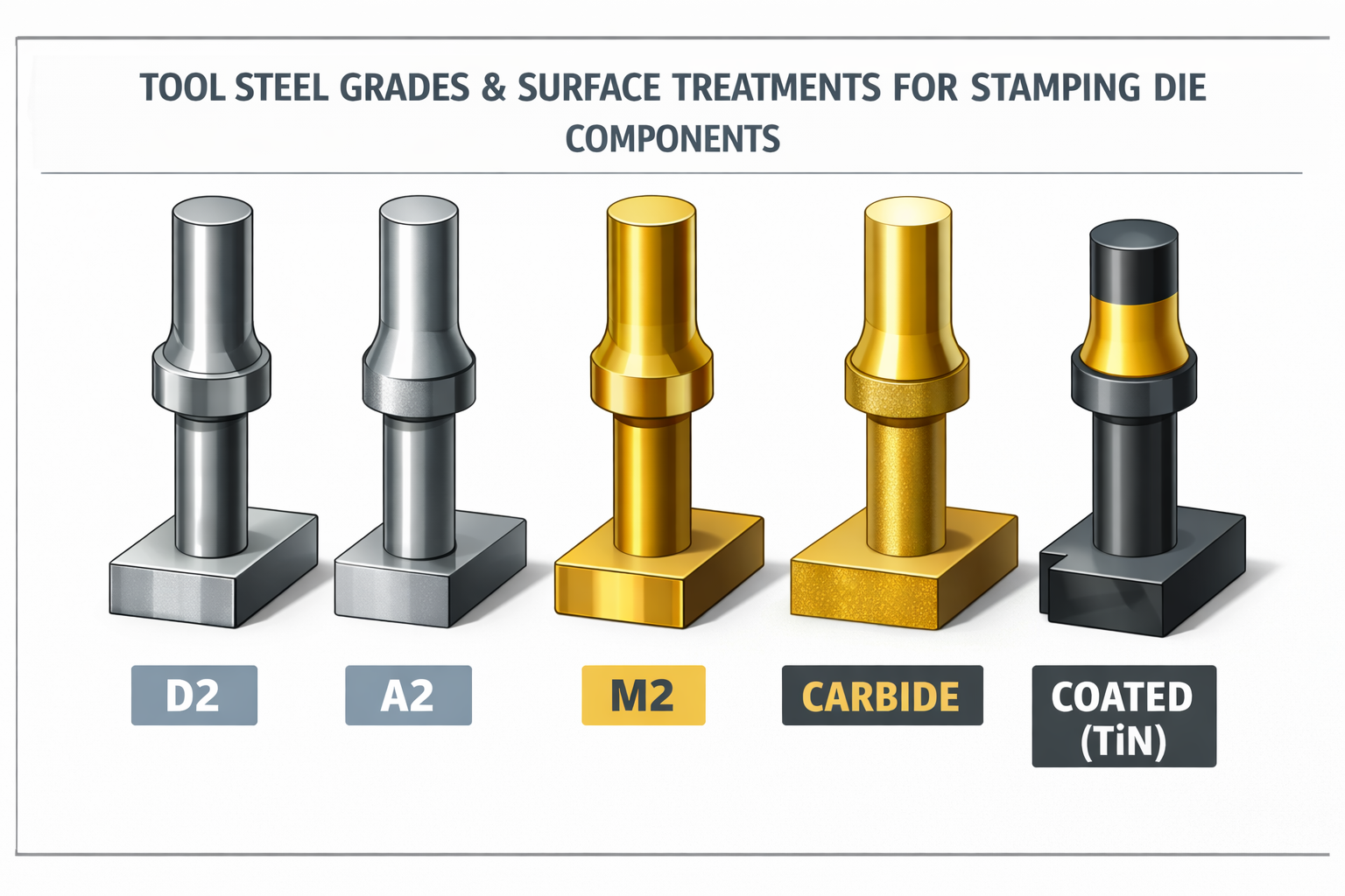
A2 Tool Steel: The Versatile Workhorse
A2 represents the go-to choice for general-purpose die components. As an air-hardening steel, it offers excellent dimensional stability during heat treatment—a critical advantage when machining tolerances must be maintained. According to the Alro Tool & Die Steel Handbook, A2 provides a good combination of wear resistance and toughness while remaining relatively easy to machine and grind.
Where does A2 excel? Consider it for:
- Stripper plates and pressure pads
- Moderate-wear forming components
- Backing plates supporting cutting elements
- Die plates in medium-volume applications
A2's machinability rating of approximately 65% compared to standard carbon steel makes it practical for complex geometries. Its size stability during heat treatment—growth typically not exceeding 0.001 inch per inch—simplifies post-heat-treatment grinding.
D2 Tool Steel: The Wear Resistance Champion
When dies manufacturing demands maximum wear resistance, D2 becomes the standard choice. This high-carbon, high-chromium steel contains substantial carbide formations that resist abrasive wear far better than lower-alloy alternatives. The AHSS Insights tooling guide notes that D2's high carbide content makes it particularly effective for stamping applications involving advanced high-strength steels.
D2 does come with trade-offs. Its machinability rating drops to approximately 40% of standard carbon steel, and its grindability is rated low to medium. These characteristics mean higher manufacturing costs—but for high-volume production of abrasive materials, the extended tool life justifies the investment.
D2 applications include:
- Blanking and piercing punches for long production runs
- Die buttons receiving hardened punches
- Trim steels and shear blades
- Form inserts subject to sliding contact with workpiece material
M2 High-Speed Steel: For Demanding Cutting Operations
When die manufacturing involves high-speed operations or materials that generate significant cutting heat, M2 high-speed steel offers properties that conventional cold work steels cannot match. M2 maintains hardness at elevated temperatures—what metallurgists call "red hardness"—allowing continued performance when friction heats cutting edges.
According to Alro's specifications, M2 achieves working hardness of 63-65 HRC while retaining toughness superior to most other high-speed steels. Its primary applications in stamping include:
- Small-diameter piercing punches in high-speed progressive dies
- Cutting components for high-strength materials
- Applications where heat buildup would soften conventional tool steels
Carbide: Extreme Wear Resistance for Demanding Applications
When even D2 cannot deliver adequate tool life, tungsten carbide inserts provide the ultimate wear resistance. Carbide's hardness—typically 90+ HRA (approximately 68+ HRC equivalent)—far exceeds any tool steel. However, this extreme hardness comes with brittleness that limits carbide to specific applications.
Carbide makes sense for:
- Piercing punches in ultra-high-volume production
- Die buttons for abrasive materials like stainless steel
- Form inserts where wear would otherwise require frequent replacement
The cost of carbide tooling typically runs 3-5 times higher than comparable D2 components. This investment pays off only when production volumes and wear rates justify the premium.
Heat Treatment Specifications for Optimal Performance
Selecting the right grade is only half the equation. Proper heat treatment transforms raw tool steel into functional die components—and improper treatment is a leading cause of premature tool failure.
The heat treatment cycle consists of three critical phases:
- Austenitizing: Heating to the hardening temperature (typically 1725-1875°F depending on grade) and holding until the steel's microstructure transforms completely
- Quenching: Controlled cooling in air, oil, or salt bath to convert austenite to hard martensite
- Tempering: Reheating to a lower temperature (typically 300-1100°F) to relieve internal stresses and adjust final hardness
Each tool steel grade requires specific treatment parameters. A2 hardens from 1725-1750°F and typically tempers at 400-500°F for cold work applications. D2 hardens at higher temperatures (1850-1875°F) and can be tempered either at low temperatures (300-500°F) for maximum hardness or double-tempered at 950-975°F for improved toughness in semi-hot work applications.
Here's a critical point many engineers miss: tempering should begin immediately after the component reaches room temperature following quenching. Delaying tempering allows internal stresses to accumulate, increasing crack risk. The Alro handbook emphasizes double tempering for highly alloyed grades—the first temper converts most retained austenite, while the second temper refines the microstructure for optimal toughness.
Hardness Requirements by Component Function
Different components demand different hardness levels based on their operational stresses:
| Component Type | Recommended Materials | Hardness Range (HRC) | Primary Performance Requirement |
|---|---|---|---|
| Piercing/Blanking Punches | D2, M2, Carbide | 58-62 | Edge retention, wear resistance |
| Die Buttons/Matrices | D2, A2, Carbide | 58-62 | Wear resistance, dimensional stability |
| Forming Punches | A2, D2, S7 | 56-60 | Wear resistance with toughness |
| Stripper Plates | A2, D2 | 54-58 | Wear resistance, guiding accuracy |
| Die Plates | A2, D2 | 58-62 | Flatness retention, wear resistance |
| Backing Plates | A2, 4140 | 45-50 | Load distribution, shock absorption |
| Die Shoes | 4140, A2 | 28-35 | Rigidity, machinability |
| Heel Blocks | A2, D2 | 54-58 | Wear resistance under sliding contact |
Notice the pattern: components that directly contact workpiece material require the highest hardness (58-62 HRC), while structural components supporting these cutting elements operate at lower hardness levels (45-50 HRC) to maintain toughness. Die shoes, which absorb shock loads without experiencing sliding wear, function effectively at even lower hardness.
Surface Treatments for Extended Component Life
Sometimes the base tool steel—even properly heat-treated—cannot deliver adequate performance. Surface treatments and coatings modify the outermost layer of components to enhance specific properties without compromising core toughness.
Nitriding diffuses nitrogen into the steel surface, creating an extremely hard case while maintaining a tough core. According to the AHSS Insights research, ion nitriding (plasma nitriding) offers advantages over conventional gas nitriding: faster processing, lower temperatures reducing distortion risk, and minimized brittle "white layer" formation. Nitriding works particularly well on H13 and similar chromium-containing steels.
Physical Vapor Deposition (PVD) Coatings apply thin, extremely hard films to component surfaces. Common coatings include:
- Titanium Nitride (TiN) – gold-colored coating providing excellent wear resistance
- Titanium Aluminum Nitride (TiAlN) – superior high-temperature performance
- Chromium Nitride (CrN) – excellent corrosion resistance with good wear properties
PVD processing occurs at relatively low temperatures (around 500°F), avoiding the distortion and softening concerns associated with higher-temperature coating methods like CVD. Multiple automotive OEMs now specify PVD coatings exclusively for cutting components used with advanced high-strength steels.
Chrome Plating has historically been used to increase wear resistance, but research shows limitations when forming advanced materials. The AHSS Insights study documents chrome-plated tools failing after 50,000 parts while ion nitrided and PVD-coated alternatives exceeded 1.2 million parts. Environmental concerns further limit chrome plating's future role.
Balancing Initial Cost Against Total Cost of Ownership
Here's where die manufacturing decisions become genuinely strategic. A D2 punch costs more than an A2 punch—but if it lasts three times longer, the total cost per part produced may be substantially lower. Smart material selection considers the complete lifecycle:
- Initial material and machining costs: Higher-alloy steels cost more and are harder to machine
- Heat treatment complexity: Some grades require vacuum or controlled-atmosphere processing
- Coating expenses: PVD and similar treatments add cost but extend service life
- Maintenance frequency: Premium materials reduce sharpening and adjustment intervals
- Downtime costs: Each die change interrupts production—longer-lasting components mean fewer interruptions
- Replacement part lead times: Complex materials may have longer procurement cycles
For short production runs, A2 or even pre-hardened steels may offer the best economics. For million-part production volumes, the investment in D2, carbide, and advanced coatings almost always pays dividends. The key is matching material investment to actual production requirements—neither over-specifying nor under-specifying.
Understanding tool steel selection sets the foundation for recognizing when components fail and why. The wear patterns and failure modes covered next will help you diagnose problems before they escalate into costly production shutdowns.
Component Wear Patterns and Failure Mode Analysis
You've invested in premium tool steels and proper heat treatment. Your die tools are running production—but nothing lasts forever. Every press stroke subjects your components to tremendous forces, and over time, even the best-engineered tooling dies show signs of wear. The question isn't whether wear will occur, but whether you'll detect it before it causes costly failures.
Here's the good news: die components rarely fail without warning. They communicate through wear patterns, part quality changes, and subtle operational differences. Learning to read these signals transforms reactive firefighting into proactive maintenance—and that distinction separates profitable operations from those plagued by unplanned downtime.
Reading Wear Patterns to Predict Component Failure
When you examine die stamp components after production runs, the wear patterns tell a story. According to industry analysis from Keneng Hardware, understanding these patterns enables engineers to predict failures before they occur and implement targeted solutions.
Edge Rounding and Cutting Edge Breakdown
Fresh cutting edges are sharp and well-defined. Over time, the repeated shearing action rounds these edges progressively. You'll notice this first as subtle changes in cut quality—slightly increased burr height or less-defined shear zones on blanked parts. As rounding progresses, cutting forces increase because the punch must compress more material before shearing begins.
What accelerates edge breakdown? Several factors contribute:
- Insufficient punch-to-die clearance causing metal compression before cutting
- Processing abrasive materials like stainless steel or high-strength steel
- Inadequate tool steel hardness for the application
- Running beyond recommended sharpening intervals
Surface Scoring and Galling Patterns
Look closely at punch bodies and die button bores. Vertical scoring lines indicate material transfer between workpiece and tooling—a precursor to galling. Research from CJ Metal Parts confirms that as dies wear, the surface finish of stamped parts becomes rough, uneven, or develops scratches and burrs because the worn die surface no longer provides uniform contact with the metal sheet.
Galling occurs when friction and pressure cause microscopic cold welding between the tool and workpiece. Once galling begins, it accelerates rapidly—the transferred material creates additional friction points, pulling more material with each stroke. Insufficient lubrication is the primary cause, but improper clearances and material compatibility issues also contribute.
Dimensional Changes and Profile Wear
Precision die stamping demands tight tolerances, but wear gradually erodes those dimensions. Die buttons enlarge as material abrades the bore. Punch diameters shrink as cutting edges break down. These changes are often subtle—measured in thousandths of an inch—but they accumulate over millions of cycles.
Monitoring part dimensions provides early warning. According to precision stamping research, even small dimensional variations can have significant impact on fit and performance. In automotive applications, slight deviations may cause assembly problems or affect vehicle safety and reliability.
Common Failure Modes and Their Causes
Beyond gradual wear, several distinct failure modes can sideline your tooling. Recognizing these patterns helps you address root causes rather than just symptoms.
Chipping from Improper Clearance
When die formed edges show chipping rather than gradual wear, suspect clearance problems. Insufficient clearance forces the punch to compress material excessively, creating shock loads that fracture hardened cutting edges. You'll see small pieces breaking away from punch tips or die button edges—sometimes ejecting into the die and causing secondary damage.
Chipping can also result from misalignment. When punches don't enter die buttons squarely, one side of the cutting edge absorbs disproportionate force. This localized overload causes fractures even when overall clearance specifications are correct.
Galling from Inadequate Lubrication
Die stamped parts that suddenly show surface defects, increased dimensional variation, or require higher press tonnage may indicate galling in progress. This adhesive wear mechanism differs fundamentally from abrasive wear—instead of material being ground away, it's being transferred and built up.
Galling prevention requires adequate lubrication reaching all contact surfaces. Dry pockets—areas where lubricant cannot flow—become galling initiation sites. Stripper surfaces, pilot bores, and forming areas with complex geometry are particularly vulnerable.
Fatigue Cracking from Excessive Cycling
Every press stroke creates stress cycles in your components. Eventually, microscopic cracks initiate at stress concentration points—sharp corners, surface defects, or material inclusions. These cracks grow incrementally until the remaining cross-section cannot carry the load, resulting in sudden fracture.
Fatigue failures often occur without obvious warning signs. The component may have been inspected and appeared fine, then failed catastrophically during the next production run. Preventing fatigue failures requires:
- Proper design avoiding sharp internal corners where stresses concentrate
- Adequate material quality with minimal inclusions or defects
- Appropriate hardness—excessively hard components are more susceptible to fatigue crack propagation
- Tracking stroke counts against established replacement intervals
Connecting Symptoms to Root Causes
When parts start showing quality issues, systematic troubleshooting identifies which components need attention. Here's a diagnostic checklist connecting observable symptoms to their likely sources:
- Burrs on part edges: Worn or rounded cutting edges on punches; insufficient punch-to-die clearance; die button bore enlargement
- Burr location shifting around holes: Guide post or bushing wear allowing punch drift; stripper plate wear affecting punch guidance
- Dimensional variation in hole sizes: Die button wear; punch diameter reduction; thermal expansion from inadequate cooling
- Dimensional drift in blanked parts: Progressive die button enlargement; guide wear affecting strip positioning; pilot wear affecting registration
- Increased punching force required: Edge rounding requiring more compression before shearing; galling increasing friction; insufficient clearance
- Surface scratches on formed parts: Galling on forming surfaces; debris in die cavities; worn or damaged forming inserts
- Inconsistent part dimensions side-to-side: Uneven guide wear; heel block wear allowing lateral die shift; press alignment deterioration
- Punch breakage: Misalignment causing side loading; insufficient clearance; material harder than specified; worn guides
- Cracking in formed areas: Worn forming radii; insufficient lubrication; material property variation
- Slug pulling (slugs sticking to punches): Insufficient die clearance; vacuum conditions in closed die sections; worn punch land surfaces
Preventive Replacement Strategies
Waiting for failure is expensive—both in scrap produced and production lost. Effective die tool management anticipates replacement needs based on objective data rather than reactive discovery.
Stroke Count Tracking
Every component has a finite service life measured in press strokes. Establish baseline expectations for each component type based on material being processed, production rates, and historical performance. Modern press controls can track stroke counts automatically, triggering maintenance alerts at predetermined intervals.
Typical replacement intervals vary dramatically by application. A carbide punch piercing mild steel might exceed 2 million strokes between sharpenings, while an A2 punch cutting stainless steel may require attention after 50,000 strokes. Document your actual experience to refine predictions over time.
Quality-Based Monitoring
Part inspection provides real-time feedback on component condition. Establish measurement protocols for critical dimensions and surface characteristics. When measurements approach tolerance limits or show consistent trends, investigate the responsible components before specifications are exceeded.
Statistical process control (SPC) techniques excel at detecting gradual wear. Control charts reveal trends that visual inspection might miss—a dimension drifting 0.0002 inches per 10,000 strokes becomes obvious on a trend chart but invisible to periodic manual checks.
Visual Inspection Protocols
According to die wear analysis best practices, regular visual inspection is the first step in analyzing wear and failure. Establish inspection schedules during die changeovers or maintenance windows. Look for:
- Edge condition on cutting components
- Surface scoring or galling on forming surfaces
- Wear patterns on guide components
- Cracks, chips, or damage on all working surfaces
- Discoloration indicating heat damage
Comparing current condition against previous inspection notes helps identify rates of change. A component that showed minor wear last month but significant wear this month warrants investigation—something may have changed in the process.
Proactive Component Replacement
Smart maintenance replaces components before they fail, scheduling work during planned downtime rather than emergency stops. Develop replacement schedules based on:
- Historical stroke counts to failure for each component type
- Quality data indicating approaching limits
- Visual inspection findings compared to rejection criteria
- Production schedules—replace before long runs, not during them
Stock critical spare components to enable quick replacement. A $200 die button sitting on the shelf costs far less than the $5,000-per-hour production loss waiting for emergency procurement.
Understanding wear patterns and failure modes equips you to catch problems early. But preventing those problems in the first place requires systematic maintenance practices—the focus of our next section.
Maintenance Best Practices for Extended Component Life
You've learned to recognize wear patterns and predict failures. But here's the real question: what separates operations that constantly fight die problems from those that run smoothly month after month? The answer lies in systematic maintenance—a proactive investment that pays dividends through reduced downtime, consistent quality, and extended component life.
What is die making without proper maintenance? It's building expensive tooling destined for premature failure. According to industry maintenance guidelines, the distinction between die maintenance and die repair is critical. Repair is reactive—fixing broken components after they've already caused production problems. Maintenance is proactive—scheduled actions designed to prevent those failures from ever occurring.
Establishing Effective Maintenance Intervals
Every stamping die requires attention at multiple intervals. Some tasks happen every shift, others weekly, and comprehensive overhauls occur periodically based on stroke counts or calendar schedules. The key is matching maintenance frequency to component wear rates and production demands.
How often should you service your metal die assemblies? Production volume and material type drive the answer. High-volume automotive applications stamping advanced high-strength steels may require maintenance every 50,000 strokes. Lower-volume operations processing mild steel might extend intervals to 100,000 strokes or beyond. Calendar-based scheduling—weekly or monthly inspections—works better for intermittent production runs.
IATF 16949-certified suppliers like Shaoyi incorporate rigorous maintenance protocols directly into their die design and manufacturing processes. This forward-thinking approach ensures components are engineered for serviceability from the start—easy access to wear items, standardized replacement parts, and clear maintenance documentation that supports extended production life.
Here's a systematic maintenance checklist organized by frequency:
-
Every production run (daily tasks):
- Inspect the last part and end of strip from the previous run for burrs, dimensional issues, or surface defects
- Check lubrication levels and verify proper lubricant distribution
- Clear debris, slugs, and metal slivers from all die surfaces
- Verify safety guards are in place and functional
- Confirm all cutting punches are secure in their retainers
-
Weekly maintenance tasks:
- Thorough cleaning of all die equipment surfaces including hidden areas where slugs accumulate
- Visual inspection of cutting edges for rounding, chipping, or damage
- Check guide pins and bushings for wear, scoring, or excessive play
- Inspect springs for fatigue, broken coils, or reduced tension
- Verify stripper plate travel and pressure
- Examine heel blocks and wear plates for galling
-
Periodic maintenance (based on stroke counts):
- Comprehensive disassembly and cleaning of all components
- Precision measurement of critical dimensions against original specifications
- Sharpening of cutting edges per established schedules
- Replacement of worn guide bushings, springs, and pilots
- Verification of punch-to-die clearances
- Surface treatment or coating reapplication as needed
-
Annual or major overhaul tasks:
- Complete die tear-down and inspection of all components
- Dimensional verification of die shoes and plates for flatness and parallelism
- Replacement of all wear items approaching end of service life
- Recalibration of die height and shut height specifications
- Update maintenance records with findings and component replacements
Sharpening Schedules and Regrind Allowances
Cutting components require periodic sharpening to maintain edge quality and part specifications. But when should you sharpen, and how much material can you remove before the component needs replacement?
According to punch press maintenance research, experts recommend sharpening tools when cutting edges wear to a 0.004-inch (0.1 mm) radius. At this point, you'll typically need to remove only 0.010 inches (0.25 mm) of material to restore sharpness. Waiting longer means more material removal and shorter overall tool life.
Three signs indicate your machine die components need sharpening:
- Feel the cutting edge: Run your finger carefully across the punch face—you'll feel the rounded edge that indicates wear
- Watch part quality: Increasing burr height and excessive rollover signal dull cutting edges
- Listen to the press: Louder punching noise often indicates the tool is working harder to cut through material
Proper sharpening technique matters as much as timing. Use flood coolant to prevent heat buildup that can damage heat treatment. Dress the grinding wheel before each session to present a clean, flat surface. Take light passes—0.001 to 0.002 inches per pass—to avoid overheating. Clamp components securely to minimize vibration and chatter marks.
Every die component has a regrind allowance—the total material that can be removed through successive sharpenings before the component falls below minimum dimension specifications. Track cumulative material removed during each sharpening cycle. When approaching the regrind limit, schedule replacement rather than squeezing out one more sharpening that leaves the component undersized.
In-Press Inspection Techniques
You don't need to pull the die for every inspection. Experienced operators develop the ability to detect problems while the stamping die remains in the press—saving time while catching issues early.
What should you monitor during production?
- Part quality indicators: Check first-off parts against specifications, then sample periodically throughout the run. Burr height, edge condition, and dimensional accuracy reveal component condition
- Press tonnage readings: Increasing tonnage requirements suggest dull cutting edges or galling—the press is working harder to accomplish the same work
- Sound changes: Dies develop characteristic sounds during normal operation. Changes in pitch, volume, or rhythm often precede failures
- Strip condition: Examine the strip between stations for pilot hole elongation, edge damage, or feeding irregularities
- Slug ejection: Consistent slug drop indicates proper die clearance and timing. Slugs sticking or ejecting erratically signal developing problems
In-press inspection works best when operators know what "normal" looks and sounds like. Document baseline conditions for each die so deviations become obvious. Train operators to report anomalies immediately rather than waiting for quality failures to confirm suspicions.
Cleaning, Lubrication, and Storage Practices
Proper cleaning removes debris that causes accelerated wear and interference with component function. After each run, clean all die machining surfaces thoroughly. Pay particular attention to:
- Slug drop openings where debris accumulates
- Stripper pockets and pilot bores
- Guide pin and bushing surfaces
- Forming surfaces where lubricant residue builds up
After cleaning, dry all surfaces completely to prevent rust formation. Apply a light protective oil coating to all steel surfaces before storage.
Lubrication requirements vary by component type. Guide pins with ball bearings require light oil only—never grease, which can contaminate the ball cage. Friction guide pins need high-pressure grease. Forming surfaces may require die lubricants compatible with your workpiece material and any downstream processes like welding or painting.
Storage practices significantly impact long-term component condition:
- Store dies in climate-controlled environments to prevent rust and corrosion
- Keep dies closed to protect cutting edges from accidental damage
- Use protective covers for dies stored in open areas
- Maintain dies in press-ready condition—don't postpone repairs until the next run
- Store spare components in organized, labeled containers for quick access during maintenance
The Maintenance Investment Equation
Every hour spent on preventive maintenance represents production time invested—but it's an investment that pays substantial returns. Consider the math: a scheduled 4-hour maintenance window costs the equivalent of 4 hours of lost production. An unplanned breakdown might cost 24 hours of emergency repair plus scrap from the failed run plus expedited shipping for replacement components.
According to industry maintenance analysis, implementing a formal preventive maintenance program delivers:
- Extended die life: Regular upkeep reduces wear and tear on critical components
- Consistent part quality: Well-maintained dies produce parts that consistently meet specifications
- Reduced downtime: Proactive maintenance catches problems before breakdowns occur
- Significant cost savings: Preventing major failures avoids emergency repair costs and lost production
Maintenance Records and Lifecycle Tracking
Documentation transforms maintenance from an art into a science. Every time die equipment is serviced, record what was done, what was found, and what was replaced. This historical data becomes invaluable for:
- Predicting component life: Track actual stroke counts between sharpenings or replacements to refine maintenance intervals
- Identifying recurring problems: Patterns emerge when you can see maintenance history across multiple runs
- Planning spare parts inventory: Know which components wear fastest and stock accordingly
- Justifying tooling investments: Compare maintenance costs across dies to identify design improvements
- Supporting warranty claims: Documented maintenance history demonstrates proper care
Modern die maintenance systems use digital tracking tied to press stroke counters. Alerts trigger automatically when maintenance intervals approach, and the system maintains complete service history accessible to maintenance technicians, engineers, and management.
Effective maintenance doesn't happen by accident—it requires commitment, documentation, and consistent execution. But for operations serious about maximizing stamping die performance, the investment in systematic maintenance protocols delivers measurable returns in uptime, quality, and component longevity. With maintenance practices established, the final step is matching components to your specific application requirements.
Selecting Components for Your Specific Stamping Applications
You've explored how stamping die components function, wear, and require maintenance. But here's the critical question that brings everything together: how do you specify the right components for your particular application? The answer isn't one-size-fits-all. A progressive die running 2 million automotive brackets demands entirely different component specifications than a compound die producing 50,000 electronic enclosures annually.
Think about it this way: buying a sports car to haul construction materials wastes money, while using an economy sedan for racing courts disaster. Sheet metal stamping dies work the same way—matching components to actual requirements optimizes both performance and cost. Let's build a systematic approach to component selection that serves your specific production needs.
Matching Components to Your Production Requirements
Your die type fundamentally shapes component selection. According to industry analysis from Worthy Hardware, understanding the difference between stamping tool and die configurations helps you specify appropriate components from the start.
Progressive Die Applications
Progressive dies perform multiple operations at different stations while the strip remains attached to the carrier material. These metal stamping die sets face unique demands:
- Components must maintain alignment across all stations simultaneously
- Pilot pins experience heavy use as the strip advances station-to-station
- Stripper plates require precise coordination with multiple punch configurations
- Material handling components work continuously throughout high-speed operation
For progressive die components, premium materials and coatings typically justify their cost. A single worn pilot can cause misregistration affecting every downstream station—cascading quality failures across the entire part. D2 tool steel or carbide pilots, combined with TiN or TiAlN coatings, deliver the wear resistance these demanding applications require.
Transfer Die Applications
Transfer dies cut the part from the strip first, then use mechanical fingers to move individual parts between stations. This approach offers advantages for certain applications. According to the Worthy Hardware comparison, transfer die stamping offers more flexibility and lower tool costs, making it ideal for lower volumes or larger parts.
Transfer die component selection differs from progressive dies:
- Forming components experience higher loads during deep drawing operations
- Guide systems must handle lateral forces from complex forming sequences
- Individual station components can be specified independently rather than as integrated systems
- Heel blocks become critical for managing side thrust during heavy forming
Compound Die Applications
Compound dies perform multiple cutting operations in a single press stroke—all cutting happens simultaneously. These metal stamping tooling configurations prioritize:
- Perfect alignment between punch and die elements since everything cuts at once
- Consistent hardness across all cutting components to ensure uniform wear
- Robust structural components to handle concentrated forces during simultaneous cutting
- Precision die plates maintaining flatness under heavy loading
Volume Considerations: When Premium Components Pay Off
Production volume dramatically influences the economics of component selection. According to Jeelix's comprehensive cost analysis, pursuing the lowest Total Cost of Ownership (TCO)—not the lowest initial price—should guide strategic procurement decisions.
Here's the math that drives volume-based decisions:
Low Volume (Under 100,000 parts)
For shorter production runs, initial component cost weighs heavily in the equation. The premium for D2 over A2, or carbide over D2, may never be recovered through extended tool life. Consider:
- A2 tool steel for most cutting components
- Standard friction guide pins rather than ball bearing assemblies
- Minimal surface treatments—perhaps nitriding on high-wear areas only
- Pre-hardened die shoes to reduce machining costs
Medium Volume (100,000 to 1,000,000 parts)
At this volume level, the balance shifts. Sharpening intervals, replacement frequency, and maintenance downtime become significant cost factors. Upgrading high-wear components often makes economic sense:
- D2 tool steel for blanking and piercing punches
- Carbide die buttons in areas processing abrasive materials
- Ball bearing guide pins for faster press speeds and easier maintenance
- TiN or similar coatings on cutting components
High Volume (Over 1,000,000 parts)
For million-part production runs, component longevity dominates the economics. Every maintenance event interrupts production, every sharpening cycle consumes capacity, every unplanned failure creates costly scrambles. Invest in:
- Carbide cutting components wherever feasible
- Advanced PVD coatings (TiAlN, AlCrN) for extreme wear resistance
- Premium ball bearing guide systems with precision preload
- Hardened and ground die shoes eliminating deflection concerns
This is where advanced simulation capabilities prove their value. Shaoyi's CAE simulation capabilities help optimize component selection before manufacturing begins—predicting wear patterns, stress concentrations, and potential failure points. This simulation-driven approach, combined with rapid prototyping available in as little as 5 days, allows validation of component specifications before committing to production tooling. The result: a 93% first-pass approval rate for automotive OEM applications, demonstrating how upfront engineering investment prevents costly trial-and-error.
Material Properties That Drive Component Specifications
What you're stamping matters as much as how many you're stamping. The workpiece material's characteristics directly influence component requirements.
Material Thickness Effects
Thicker materials require:
- Increased punch-to-die clearances (percentage of thickness remains similar, but absolute clearance grows)
- More robust structural components to handle higher cutting forces
- Stiffer die shoes to prevent deflection under load
- Stronger stripper systems to handle increased stripping forces
Tensile Strength Considerations
High-strength steels, stainless steels, and work-hardened materials dramatically accelerate component wear. Processing these materials demands:
- Premium tool steels (D2 minimum, carbide preferred for critical cutting elements)
- Advanced surface treatments (ion nitriding, PVD coatings)
- Increased clearances to reduce cutting forces
- Robust guide systems to handle higher operational loads
Work Hardening Characteristics
Materials like stainless steel and certain aluminum alloys work-harden during forming—they become harder and stronger as they're deformed. This creates unique challenges:
- Forming components must be harder than the work-hardened material condition
- Multiple forming stages may require progressively harder tooling
- Surface treatments become essential to prevent galling with work-hardened surfaces
Component Selection Decision Matrix
Bringing these factors together, the following decision matrix connects your application characteristics to specific component recommendations:
| Application Factor | Low Volume / Mild Steel | Medium Volume / Standard Materials | High Volume / Advanced Materials |
|---|---|---|---|
| Cutting Punches | A2 tool steel, 58-60 HRC | D2 tool steel with TiN coating | Carbide or PM tool steel with TiAlN |
| Die Buttons | A2 or D2 tool steel | D2 with surface treatment | Carbide inserts |
| Guide Systems | Friction pins with bronze bushings | Ball bearing guides | Precision ball bearing with preload |
| Stripper Plates | A2 tool steel, 54-56 HRC | D2 with nitriding | D2 with PVD coating |
| Die Shoes | Pre-hardened 4140 steel | A2 tool steel, precision ground | Hardened A2 or D2, stress relieved |
| Forming Inserts | A2 or S7 tool steel | D2 with surface treatment | Carbide or coated D2 |
| Pilots | A2 tool steel | D2 with TiN coating | Carbide with advanced coating |
| Surface Treatments | Minimal—nitriding on critical areas | Nitriding plus TiN on cutting edges | Full PVD coating system |
Building a Component Specification Checklist
Before finalizing stamping die design specifications, work through this checklist to ensure all factors are considered:
Production Requirements
- What is the total expected production volume over the die's lifetime?
- What annual or monthly volumes will the die need to support?
- What press speeds are required to meet production targets?
- How critical is uptime—what's the cost of unplanned downtime?
Material Characteristics
- What material type will be processed (steel, stainless, aluminum, other)?
- What is the material thickness range?
- What are the material's tensile strength and hardness specifications?
- Does the material work-harden during forming operations?
- Are there surface finish requirements on the workpiece?
Part Complexity
- How many operations are required to complete the part?
- What tolerances must the die maintain throughout production?
- Are there deep drawing or complex forming operations?
- What is the smallest feature size (affects minimum punch diameters)?
Maintenance Considerations
- What maintenance resources are available in-house?
- What is the acceptable maintenance interval based on production scheduling?
- Are spare components available for quick replacement?
- Is component standardization possible across multiple dies?
Total Cost of Ownership: The Complete Picture
Smart metal stamping die design balances initial investment against long-term operational costs. According to cost analysis research, a low-priced die typically signals compromises that return as multiplied costs during production.
Consider the full cost equation:
Initial Costs
- Component materials and heat treatment
- Precision machining and grinding
- Surface treatments and coatings
- Assembly and tryout
Operational Costs
- Sharpening labor and consumables
- Planned maintenance downtime
- Component replacement parts
- Quality inspection and verification
Failure Costs
- Unplanned downtime (often 5-10x the cost of planned maintenance)
- Scrap produced before failure detection
- Emergency repair labor and expediting
- Secondary damage to other die components
- Customer impact from missed deliveries
Premium progressive die components cost more upfront but often deliver the lowest total cost per part produced. A carbide punch costing $500 that produces 2 million parts delivers a per-part tooling cost of $0.00025. An A2 punch costing $100 that requires replacement every 200,000 parts—with each change taking 30 minutes of production time—may actually cost more over the same production volume.
The goal isn't spending the least—or the most. It's matching component investment to actual production demands. Specify A2 where A2 suffices. Invest in carbide where wear rates justify the premium. Apply coatings where they deliver measurable life extension. And partner with suppliers who understand this balance—those who can analyze your application and recommend the right components rather than simply quoting whatever you request.
By systematically evaluating your production requirements, material characteristics, and total cost considerations, you'll specify stamping die components that deliver reliable performance throughout their intended service life—avoiding both the false economy of under-specification and the waste of over-engineering.
Frequently Asked Questions About Stamping Die Components
1. What are the basic components of a stamping die?
A stamping die consists of several integrated component categories: structural foundation elements (die shoes, die plates, and die sets), cutting elements (punches and die buttons), guiding systems (guide posts, bushings, and heel blocks), and material handling components (pilots, stock guides, and lifters). These components work together as a system to transform flat sheet metal into precision parts through cutting, bending, and forming operations.
2. How do I determine the correct punch-to-die clearance?
Punch-to-die clearance is calculated as a percentage of material thickness per side. The standard starting point is 10% per side, though 11-20% clearance can reduce tooling strain and extend operational life. Key factors include material type (stainless steel needs around 13% per side), material thickness, desired edge quality, and tool life requirements. Calculate clearance using: Clearance per side = Material thickness × Clearance percentage.
3. What tool steel grades are best for stamping die components?
Tool steel selection depends on component function. A2 tool steel works well for general-purpose components like stripper plates and moderate-wear forming tools. D2 provides superior wear resistance for blanking punches, die buttons, and trim steels. M2 high-speed steel handles high-speed operations where heat buildup is a concern. Carbide delivers extreme wear resistance for ultra-high-volume production, though at 3-5 times the cost of D2 components.
4. How often should stamping die components be maintained?
Maintenance intervals depend on production volume and material type. High-volume automotive applications stamping advanced high-strength steels may require maintenance every 50,000 strokes, while lower-volume operations with mild steel can extend to 100,000 strokes or more. Daily tasks include inspecting parts for burrs and checking lubrication. Weekly tasks cover cleaning, visual inspection of cutting edges, and checking guide components. Periodic overhauls based on stroke counts include sharpening and component replacement.
5. What causes premature punch breakage in stamping dies?
Punch breakage typically results from several factors: misalignment causing side loading when punches contact die buttons off-center, insufficient clearance creating shock loads that fracture hardened cutting edges, worn guide components allowing punch drift, and processing materials harder than specified. Worn guide posts and bushings are often the root cause, as they allow punches to enter die buttons at incorrect angles, concentrating stress on one side of the cutting edge.