 Small batches, high standards. Our rapid prototyping service makes validation faster and easier —

Punch And Die Clearance Chart: Stop Guessing, Start Cutting Clean
Understanding Punch and Die Clearance Fundamentals
Ever wonder why some stamped parts come out with perfectly clean edges while others look ragged and torn? The secret often lies in a measurement so small you might overlook it entirely. We're talking about punch and die clearance—a critical specification that separates professional-grade metalworking from frustrating trial-and-error.
What Punch and Die Clearance Actually Means
Simply put, punch and die clearance refers to the gap between the cutting punch and the corresponding die opening. When you're working with a blanking die or any stamping operation, this gap exists on all sides of the punch. The measurement is typically expressed as a percentage of material thickness per side—not the total gap, but the space on each individual side.
Imagine sliding a piece of sheet metal between the punch and die. The clearance determines how much "breathing room" exists around the punch as it drives through the material. Too tight, and you're forcing metal where it doesn't want to go. Too loose, and you lose control over how the material separates.
For example, if you're punching 0.060-inch mild steel with a 10% clearance per side, your total die opening would be 0.012 inches larger than your punch diameter (0.006 inches on each side). These numbers might seem insignificant, but they're the difference between a smooth operation and a maintenance nightmare.
Why Thousandths of an Inch Matter in Metal Stamping
You might be thinking: "It's just a few thousandths of an inch. How much could it really matter?" The answer is—everything. When a die punch penetrates sheet metal, it initiates a complex sequence of deformation and fracture. Proper clearance ensures that fracture lines originating from both the punch edge and the die edge meet cleanly in the middle of the material.
When clearance is correctly specified, fracture lines from the punch and die propagate toward each other and meet cleanly, creating a smooth, consistent edge with minimal burr formation.
This clean meeting of fracture zones directly impacts three critical production factors:
- Part Quality: Correct clearance produces edges with controlled shear zones and minimal burrs, reducing or eliminating secondary finishing operations.
- Tool Life: When metal punches and dies operate within optimal clearance ranges, wear distributes evenly, extending service intervals significantly.
- Production Efficiency: Fewer rejected parts, less downtime for tool changes, and reduced operator intervention all stem from dialing in the right clearance from the start.
Throughout this guide, you'll find comprehensive reference charts organized by material type, thickness considerations, and troubleshooting tables you can apply immediately on the shop floor. Whether you're setting up a new blanking die or diagnosing edge quality problems on an existing operation, this resource gives you the data and methodology to stop guessing and start cutting clean.
The Science Behind Proper Die Clearance
Understanding why clearance matters goes beyond simple measurements—it requires looking at what actually happens inside the metal during a punching operation. When a metal die punch drives into sheet material, it triggers a fascinating sequence of mechanical events at the microscopic level. Grasping this science helps you predict outcomes and select clearances that deliver consistently clean results.
The Three Zones of a Punched Edge
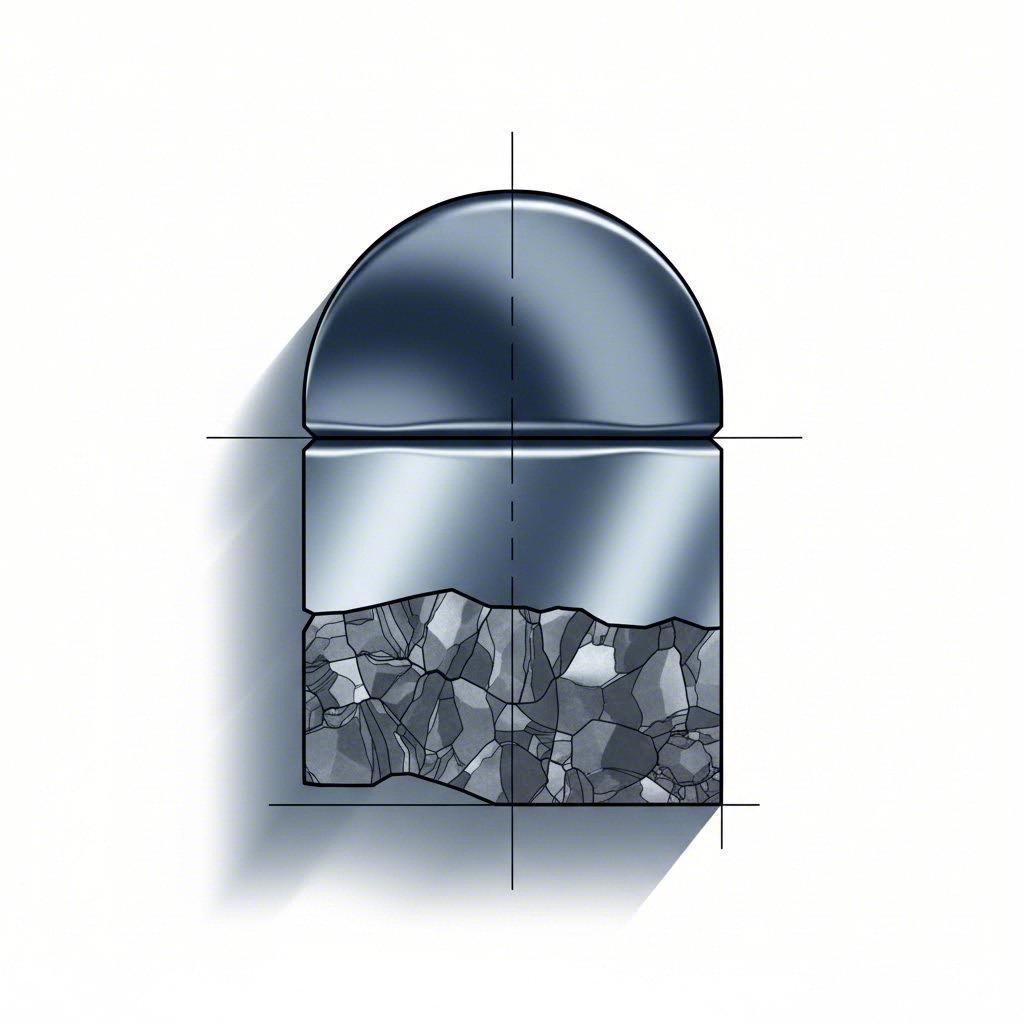
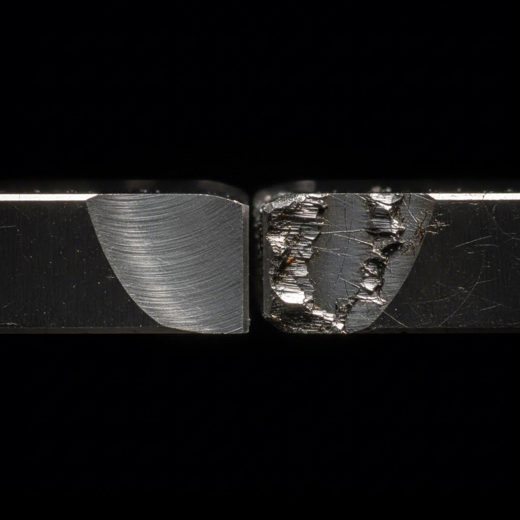
Take a close look at any punched edge under magnification, and you'll notice it isn't uniform. The edge profile reveals three distinct zones, each created during a different phase of the punching process. Recognizing these zones helps you diagnose problems and understand why your current clearance settings produce specific results.
- Roll-Over Zone (Burnish Radius): This is the rounded portion at the top of the cut edge where the punch first contacts the material. As the punch begins its descent, it draws the material downward before cutting begins. This zone typically represents 5-10% of total material thickness and appears as a smooth, slightly curved surface.
- Shear Zone (Burnish Band): Directly below the roll-over, you'll find the shear zone—a smooth, shiny band where the punch actually cut through the metal. This zone represents true shearing action and typically accounts for 25-50% of material thickness when clearance is properly set. The smoother and larger this zone, the cleaner your cut.
- Fracture Zone (Break): The remaining portion of the edge shows a rougher, crystalline appearance where the material fractured rather than sheared. This zone typically represents 40-60% of material thickness. When clearance is correct, fracture lines from the punch edge and die edge meet cleanly, creating a consistent break angle.
The relative proportions of these zones tell you everything about your clearance setup. A die cut punch operation with optimal clearance produces a balanced edge profile with clean transitions between zones. When you see irregularities—excessive rollover, minimal shear band, or jagged fracture zones—you're looking at clearance problems waiting to be solved.
How Metal Fractures During the Punching Process
Here's where metallurgy meets real-world stamping. Sheet metal isn't a uniform solid—it's composed of countless tiny crystalline grains packed together in a polycrystalline structure. When your punch applies force, these grains respond in predictable ways that depend heavily on clearance settings.
During the initial punch descent, compressive stress builds in the material directly beneath the punch edge and above the die edge. With proper clearance, these stress concentrations create fracture initiation points that propagate toward each other at controlled angles. The fractures meet in the middle of the material thickness, completing the separation cleanly.
When clearance is too tight, problems emerge quickly. The punch and die edges are positioned so close together that the natural fracture propagation gets interrupted. Instead of fractures meeting cleanly, the material undergoes secondary shear—essentially being cut twice. This doubles the stress on your tooling edges, accelerating wear dramatically. You'll notice increased punching force requirements and see punch edges developing micro-chips or premature rounding.
Loose clearance creates the opposite problem. When the gap between punch and die exceeds optimal ranges, fracture lines don't align properly. The material bends and tears rather than shearing cleanly, producing heavy burrs on the die side of your workpiece. These burrs aren't just cosmetic issues—they represent wasted material, potential handling injuries, and often require secondary deburring operations that add cost to every part.
The maximum punch penetration before fracture also depends on clearance. With correct settings, the punch typically penetrates 30-50% of material thickness before fractures complete the separation. Too-tight clearance forces deeper penetration and higher forces. Too-loose clearance allows excessive material deformation before separation occurs.
Understanding this science transforms clearance selection from guesswork into predictable engineering. You're not just following a chart—you're controlling the physics of metal fracture to achieve the edge quality your application demands.
Complete Material Clearance Percentage Reference Chart
Now that you understand the science behind how metal fractures during punching, it's time to put that knowledge into action. The following punch die clearance recommendations give you reliable starting points for virtually any material you'll encounter on the shop floor. Think of these percentages as your foundation—solid enough to build on, flexible enough to adjust when specific applications demand it.
Standard Clearance Percentages by Material
Every material responds differently to shearing forces based on its unique grain structure, hardness, and ductility. The chart below organizes clearance percentages per side for the most common sheet metal punches and dies applications. Remember, these values represent the gap on each side of the punch—not the total clearance.
| Material Type | Clearance Percentage Per Side | Notes/Considerations |
|---|---|---|
| Mild Steel (Low Carbon) | 5-10% | Standard baseline for most stamping operations. Use lower end for thinner gauges and precision work; higher end for heavy gauge and roughing operations. |
| Stainless Steel (300 Series) | 10-14% | Work hardening requires increased clearance to prevent excessive tool wear. Austenitic grades particularly demanding on tooling. |
| Stainless Steel (400 Series) | 8-12% | Ferritic and martensitic grades slightly more forgiving than austenitic. Still requires elevated clearance compared to mild steel. |
| Aluminum (Soft Tempers) | 3-6% | Soft, ductile material cuts cleanly with tighter clearance. Excessive clearance causes significant burring and edge rollover. |
| Aluminum (Hard Tempers) | 5-8% | Heat-treated alloys like 6061-T6 and 7075 require slightly more clearance than annealed grades. |
| Brass | 4-7% | Excellent shearing characteristics. Lower clearance produces exceptionally clean edges suitable for decorative applications. |
| Copper (Soft) | 3-6% | Similar to soft aluminum. Gummy material may benefit from slightly tighter clearance to prevent burr adhesion. |
| Copper (Half-Hard to Hard) | 5-8% | Work-hardened copper requires clearance adjustment upward to prevent excessive punch wear. |
| Galvanized Steel | 6-10% | Base clearance similar to mild steel. Zinc coating may cause slight burring; clearance at higher end helps minimize coating damage. |
| Silicon Steel (Electrical) | 3-6% | Brittle material fractures cleanly with tight clearance. Critical for lamination applications where edge quality affects magnetic performance. |
You'll notice that softer, more ductile materials generally require tighter clearances, while harder materials need more room for fractures to propagate correctly. This pattern holds true across most metal punches and dies applications, though specific alloy compositions can shift these recommendations.
Special Considerations for High-Strength Steels
Here's where many operators run into trouble. Advanced High-Strength Steels (AHSS) and exotic alloys have become increasingly common in automotive and aerospace applications, yet clearance guidance for these materials remains scarce. Experienced toolmakers at facilities like Cleveland Tool and Die have long recognized that standard charts don't tell the whole story when you're punching today's demanding materials.
| Material Type | Clearance Percentage Per Side | Notes/Considerations |
|---|---|---|
| HSLA Steel | 8-12% | High-Strength Low-Alloy steels require elevated clearance. Punch life significantly affected by clearance optimization. |
| Dual Phase (DP) Steel | 10-15% | Martensite islands in ferrite matrix demand generous clearance. Expect higher punching forces than tensile strength alone suggests. |
| TRIP Steel | 12-16% | Transformation-induced plasticity creates unpredictable edge behavior. Start at higher clearance and adjust based on results. |
| Martensitic Steel | 12-18% | Extremely hard material requires maximum clearance ranges. Tool steel selection critical for punch survival. |
| Inconel/Nickel Alloys | 12-16% | Work hardening severe. Carbide tooling often required. Clearance optimization essential for any reasonable tool life. |
| Titanium Alloys | 10-15% | Springback significant. Material galls easily; clearance and lubrication both critical for success. |
When working with AHSS materials, the traditional approach of selecting clearance based solely on material type often falls short. Hardness testing provides more actionable guidance than generic material categories. As a general rule, increase your baseline clearance by 1-2% for every 10 HRC points above 30. This adjustment accounts for the increased brittleness and fracture resistance that accompanies higher hardness levels.
Temper conditions also play a significant role that material type alone doesn't capture. An annealed stainless steel blank behaves dramatically differently than the same alloy in a cold-worked condition. Shops like Cleveland Tool and Die often maintain separate clearance specifications for different temper states of the same base material—a practice worth adopting if you regularly work with materials in varying conditions.
Keep in mind that these percentages represent starting points, not absolute rules. Your specific application may demand adjustments based on hole size relative to material thickness, required edge quality specifications, acceptable burr height, and production volume considerations that affect how aggressively you can push tool life. The next section explores how material thickness itself influences optimal clearance selection and walks through the calculations you'll need to convert these percentages into actual die opening dimensions.

Die Clearance Calculations and Thickness Variables
You've got your material clearance percentages dialed in—but here's the catch. Those percentages only tell part of the story. Material thickness introduces a critical variable that can shift your optimal clearance significantly. A 10% clearance that works perfectly for 0.060-inch mild steel might produce entirely different results when you're punching 0.250-inch plate of the same material. Let's break down exactly how thickness affects your calculations and walk through the math you'll use every time you set up a new job.
Calculating Die Opening from Punch Size
Every punch calculator or die calculator starts with the same fundamental formula. Once you understand this relationship, you can derive die opening dimensions for any combination of punch size, material thickness, and clearance percentage.
The core formula is straightforward:
Die Opening = Punch Size + (2 × Clearance Per Side)
Why multiply by two? Because clearance exists on both sides of the punch. When you specify 10% clearance per side, that gap appears around the entire punch circumference—so your total die opening grows by twice the per-side clearance value.
Here's how to apply this formula step by step:
- Identify your punch diameter or dimension. For this example, let's use a 0.500-inch round punch.
- Determine material thickness. We'll work with 0.062-inch mild steel.
- Select clearance percentage from your reference chart. Mild steel typically uses 5-10%. For this medium-gauge material, we'll use 8%.
- Calculate clearance per side in inches. Multiply thickness by percentage: 0.062 × 0.08 = 0.00496 inches (round to 0.005 inches).
- Calculate total clearance. Multiply per-side clearance by 2: 0.005 × 2 = 0.010 inches.
- Add total clearance to punch size. Die Opening = 0.500 + 0.010 = 0.510 inches.
Your die size calculator output: a 0.510-inch die opening for a 0.500-inch punch in 0.062-inch mild steel at 8% clearance per side.
When working with fractional dimensions, the same logic applies—though you'll want to convert to decimals for accuracy. Wondering about comparisons like 23/32 vs 5/8? Converting these fractions (0.71875 vs 0.625 inches) before running your calculations prevents costly errors. Similarly, questions like "is 15/32 the same as 5/8" come up regularly in the shop. Quick answer: no—15/32 equals 0.46875 inches while 5/8 equals 0.625 inches. Always verify your dimensional conversions before calculating die openings.
Thickness Considerations for Thin vs Heavy Gauge
Here's where experience separates good toolmakers from great ones. The clearance percentages in standard charts assume mid-range thicknesses—roughly 0.040 to 0.125 inches for most materials. Step outside that range, and you'll need to adjust your approach.
Thin Gauge Materials (Under 1mm / 0.040 inches): Thin materials present unique challenges. The fracture zone becomes proportionally smaller, and even slight clearance variations produce noticeable edge quality differences. Most experienced operators reduce their baseline clearance percentage by 1-3% when working with thin gauge stock. This tighter clearance helps maintain the shear-to-fracture ratio that produces clean edges.
Heavy Gauge Materials (Over 0.125 inches): Thicker materials require more clearance to allow proper fracture propagation. The increased material mass resists shearing, and tight clearances force the punch to work harder—accelerating wear and increasing required tonnage. Adding 1-3% to your baseline percentage for heavy gauge work extends tool life without sacrificing acceptable edge quality.
The following table shows how clearance recommendations shift across thickness ranges for common materials:
| Material | Thin Gauge (<0.040") | Medium Gauge (0.040-0.125") | Heavy Gauge (>0.125") |
|---|---|---|---|
| Mild Steel | 4-7% | 5-10% | 8-12% |
| Stainless Steel (300 Series) | 8-11% | 10-14% | 12-16% |
| Aluminum (Soft) | 2-4% | 3-6% | 5-8% |
| Aluminum (Hard) | 4-6% | 5-8% | 7-10% |
| Brass | 3-5% | 4-7% | 6-9% |
| Copper (Soft) | 2-4% | 3-6% | 5-8% |
| HSLA Steel | 6-9% | 8-12% | 10-15% |
Notice the pattern? As thickness increases, optimal clearance percentages shift upward across all material types. This adjustment accounts for the increased energy required to initiate and propagate fractures through more material mass.
One more practical consideration: when your size die calculations produce dimensions that fall between standard tooling increments, round to the nearest available size—but always round toward more clearance rather than less. Slightly loose clearance produces manageable burrs you can address. Excessively tight clearance causes tool damage that shuts down production.
With your calculations complete, the next critical step is recognizing when something goes wrong. Edge defects, unusual wear patterns, and production problems often trace directly back to clearance issues—and knowing how to diagnose these symptoms saves hours of troubleshooting.
Troubleshooting Common Clearance-Related Defects
You've done the calculations, selected your percentages, and set up your tooling—but the parts coming off the press tell a different story. Burrs that catch your gloves, edges that look torn rather than cut, punches wearing out faster than they should. Sound familiar? These symptoms aren't random manufacturing headaches. They're your parts telling you exactly what's wrong with your clearance settings.
Learning to read these defects turns frustrating production problems into straightforward fixes. Every edge quality issue, every unusual wear pattern, traces back to the physics of how metal separates during punching. Once you understand what each symptom means, you can diagnose problems in minutes instead of hours.
Diagnosing Clearance Problems from Part Defects
Think of punched part defects as diagnostic messages from your tooling. Each problem type points toward a specific clearance condition—too tight, too loose, or sometimes uneven across the punch profile. The table below connects common symptoms directly to their likely causes and recommended corrections.
| Problem/Symptom | Likely Clearance Issue | Recommended Correction |
|---|---|---|
| Excessive burr height on die side | Clearance too loose | Reduce clearance by 1-3%. Material is bending and tearing rather than shearing cleanly. Fracture lines aren't meeting properly. |
| Burr on punch side (reverse burr) | Clearance too tight | Increase clearance by 2-4%. Secondary shearing is occurring, forcing material upward around the punch. |
| Rough, torn edge appearance | Clearance too loose or uneven | Verify clearance uniformity around punch perimeter. Reduce clearance if consistently loose. Check die/punch alignment. |
| Excessive rollover zone | Clearance too loose | Tighten clearance to reduce material deformation before fracture initiates. Consider hold-down pressure adjustment as secondary factor. |
| Minimal shear band (mostly fracture) | Clearance too loose | Reduce clearance to extend the shearing phase. Clean shear zones require punch and die edges to work in closer proximity. |
| Premature punch edge wear/rounding | Clearance too tight | Increase clearance to reduce side pressure on punch. Tight clearance forces punch to do extra work, accelerating wear. |
| Die edge chipping or spalling | Clearance too tight | Increase clearance immediately. Chipping indicates severe stress concentration. Verify die steel hardness is appropriate for material. |
| Slug pulling (slug sticks to punch) | Clearance too tight | Increase clearance by 2-3%. Tight clearance creates vacuum effect and compression fit. Consider adding slug ejection if problem persists. |
| Slug pushing (slug doesn't eject cleanly) | Clearance too loose | Tighten clearance for better slug control. Loose slugs may also indicate worn die opening or insufficient die relief. |
| Inconsistent edge quality around hole | Uneven clearance (misalignment) | Check punch-to-die concentricity. Regrind or replace components showing uneven wear. Verify press alignment and guide system condition. |
| Higher than expected punching force | Clearance too tight | Increase clearance to reduce required tonnage. Use a punch force calculator to verify expected versus actual force requirements. |
When using a punching force calculator to estimate tonnage requirements, remember that clearance affects more than just edge quality. Tight clearance can increase your required pounds per square inch punch force by 20-30% compared to optimal settings. If your press is struggling with what should be routine work, clearance is often the culprit.
When Burrs and Rough Edges Signal Wrong Clearance
Burrs deserve special attention because they're the most common clearance-related complaint—and the most misunderstood. Not all burrs indicate the same problem, and the burr location tells you which direction to adjust.
Die-side burrs (bottom of workpiece): These form when clearance is too loose. The material bends into the oversized die opening before fracturing, leaving a raised edge that points downward. The fix is straightforward: reduce your clearance percentage and watch burr height decrease.
Punch-side burrs (top of workpiece): Less common but more troubling. These reverse burrs indicate clearance so tight that secondary shearing occurs. Metal actually flows upward around the punch during retraction. You'll also notice increased punch wear when this happens. Open up your clearance immediately—this condition damages tooling quickly.
Rough or torn edges often accompany loose clearance, but they can also signal uneven clearance around the punch perimeter. Before adjusting your overall clearance percentage, check alignment. A punch that's 0.001 inches off-center creates dramatically different clearance on opposing sides, producing good edges on one side and torn edges on the other.
Here's when to intentionally deviate from standard percentages:
- Precision hole applications: When hole location and diameter tolerances are critical, tighter clearance (lower end of recommended range) produces more consistent results. Accept slightly higher tool wear in exchange for dimensional accuracy.
- Rough blanking operations: When edge quality is secondary to production speed and tool longevity, running at the higher end of clearance ranges extends sharpening intervals. The extra burr is acceptable if parts go to secondary finishing anyway.
- High-volume production: Consider starting with slightly loose clearance to maximize initial tool life, then tighten as edges wear. This approach maintains acceptable quality longer between sharpening cycles.
- Prototype or short runs: Tighter clearance makes sense when you need the best possible parts and tool life is less critical. Optimize for quality when quantity isn't the priority.
The defects you observe today contain all the information you need to improve tomorrow's production. But diagnosis only matters if you can accurately measure your current clearance settings—which brings us to the practical techniques for verification on the shop floor.
How to Measure and Verify Die Clearance in Your Shop
Diagnosing clearance problems from part defects gives you direction—but confirming your actual clearance values requires hands-on measurement. Surprisingly few shops have systematic procedures for verifying die clearance, yet this step separates consistent production from ongoing guesswork. Whether you're setting up new tooling, investigating quality issues, or confirming wear hasn't shifted your specifications, these practical techniques put real numbers behind your clearance settings.
Methods for Measuring Existing Die Clearance
Several measurement approaches work on the shop floor, each with distinct advantages depending on your accuracy requirements and available equipment. Think of the clearance lab as wherever you perform these checks—whether that's a dedicated quality room or right at the press.
Feeler Gauge Method: The most accessible approach for quick verification. Insert calibrated feeler gauge blades between the punch and die opening to measure the gap directly. This method works best for larger clearances (above 0.003 inches) and provides immediate feedback during setup.
Optical Comparator Method: When precision matters, an optical comparator magnifies the punch and die profiles for accurate measurement. This technique reveals not just clearance values but also edge wear patterns invisible to the naked eye. Ideal for quality audits and troubleshooting persistent edge quality issues.
Paper/Shim Technique: A practical field method using calibrated shim stock or paper of known thickness. By testing which shim thicknesses fit the clearance gap, you can bracket the actual clearance value quickly. Less precise than other methods but useful for rapid checks when dedicated measuring equipment isn't available.
Required measurement tools for comprehensive clearance verification:
- Feeler gauge set (0.001 to 0.025 inch increments)
- Calibrated shim stock in various thicknesses
- Dial indicator with magnetic base for alignment checks
- Optical comparator or toolmaker's microscope (for precision work)
- Pin gauges matching your standard punch sizes
- Inside micrometers for die opening measurements
Verification Techniques for Quality Assurance
Measuring clearance once during setup isn't enough. Wear changes clearance over time, and what started as optimal specifications can drift into problem territory without warning. Establishing verification procedures catches these changes before they affect part quality.
Step-by-step verification procedure:
- Remove the punch and die set from the press for accurate measurement
- Clean all surfaces thoroughly—debris creates false readings
- Measure punch diameter at multiple points to detect wear or out-of-round conditions
- Measure die opening using pin gauges or inside micrometers
- Calculate actual clearance: (Die Opening - Punch Diameter) ÷ 2 = Clearance Per Side
- Compare measured values against documented specifications
- Record all measurements with date and stroke count for trend analysis
How often should you verify? High-volume operations punching abrasive materials like stainless steel benefit from weekly checks. Standard mild steel applications typically need monthly verification. Any time edge quality changes noticeably, immediate measurement helps identify whether clearance has shifted. Unlike a creepage clearance calculator used in electrical applications or a piston to valve clearance calculator for engine work, die clearance verification requires physical measurement—no calculation substitutes for actual inspection.
Signs that clearance has changed due to wear include gradual burr height increase, edge quality degradation over time, and increased punching force requirements. Punch edges round off and die openings enlarge as material flows through the tooling. For a 10 clearance hole specification, even 0.0005-inch wear on the punch combined with 0.0005-inch die enlargement shifts your per-side clearance noticeably.
Document your clearance specifications thoroughly. Recording initial clearance values, material processed, stroke counts between measurements, and observed wear patterns creates invaluable data for predicting maintenance needs. When you're running a 3 8 punch or any standard size, historical records help you anticipate when regrinding or replacement becomes necessary—before quality suffers.
With measurement and documentation systems in place, you've built the foundation for consistent, predictable stamping operations. The next step connects these practices to the broader goal of precision tooling that delivers defect-free production run after run.

Precision Tooling and Optimal Clearance Engineering
You've mastered the fundamentals—clearance percentages, thickness calculations, defect diagnosis, and measurement techniques. Now comes the question that separates good stamping operations from exceptional ones: how do you translate all this knowledge into tooling that performs flawlessly from the first stroke? The answer lies in precision engineering that builds optimal clearance into every punch and die set before it ever touches your press.
Clearance Precision in High-Volume Production
When you're running thousands or millions of parts, the margin for error shrinks dramatically. A clearance specification that's slightly off might produce acceptable parts during a prototype run—but multiply that small deviation across a production campaign, and problems compound quickly.
Consider what proper clearance engineering delivers in high-volume scenarios:
- Reduced scrap rates: Precision-engineered punch and die tooling with optimized clearance specifications produces consistent edge quality from first part to last. You're not adjusting on the fly or sorting out marginal parts.
- Extended tool life: When clearance is engineered correctly from the start, wear distributes evenly across cutting edges. Dies and punches reach their full service potential rather than failing prematurely from stress concentrations caused by improper gaps.
- Improved first-pass approval rates: Parts that meet specifications immediately reduce rework, secondary operations, and quality holds. Every percentage point improvement in first-pass approval translates directly to bottom-line savings.
- Lower per-part costs: Combining reduced scrap, extended tool life, and fewer quality interventions drives your cost per piece down—exactly where competitive manufacturing demands it.
The challenge? Achieving this level of precision requires more than selecting the right percentage from a chart. It demands tooling designed and manufactured to hold those specifications consistently across the entire die and punch profile.
Engineering Excellence for Defect-Free Stamping
Here's where modern manufacturing technology transforms clearance selection from educated guessing into predictable engineering. Advanced simulation technologies—particularly Computer-Aided Engineering (CAE)—now allow toolmakers to model exactly how material will behave during punching before any steel is cut.
CAE simulation predicts fracture propagation paths, identifies stress concentration points, and optimizes clearance values for specific material and thickness combinations. Instead of building a die, testing it, finding problems, and regrinding, simulation catches issues digitally. The result? Tooling that works correctly the first time.
This simulation-first approach becomes especially valuable when working with challenging materials like AHSS or exotic alloys where standard clearance charts provide only rough guidance. CAE models account for material-specific fracture behavior, work hardening characteristics, and thickness variations that no static chart can address.
Manufacturers holding IATF 16949 certification—the automotive industry's quality management standard—increasingly rely on these simulation capabilities to meet demanding OEM specifications. For example, Shaoyi's precision stamping die solutions combine advanced CAE simulation with rigorous quality systems to optimize clearance specifications before physical tooling production begins. Their approach achieves a 93% first-pass approval rate—demonstrating what's possible when engineering precision replaces trial-and-error adjustment.
What does this mean for your operation? When evaluating punch dies suppliers, look beyond basic tooling capabilities. Ask about simulation and analysis processes. Inquire how clearance specifications are determined and validated. Suppliers who engineer clearance rather than simply machining to generic values deliver tooling that performs from day one.
Whether you're sourcing new die and punch sets or upgrading existing tooling, the integration of CAE simulation, quality certification, and clearance optimization represents the current state of the art. Rapid prototyping capabilities—sometimes delivering functional tooling in as little as five days—mean you can validate performance quickly without committing to full production quantities.
The bottom line: precision-engineered tooling with optimized clearance doesn't cost more in the long run. It costs less—through reduced scrap, extended service life, and parts that pass inspection the first time. That's the payoff for moving beyond charts and calculations to true engineering excellence.
Applying Clearance Knowledge to Your Stamping Operations
You've journeyed through the science of metal fracture, studied material-specific clearance percentages, learned calculation methods, mastered defect diagnosis, and explored measurement techniques. Now it's time to pull everything together into a workflow you can follow for any punching application—whether you're setting up a new die cut puncher or troubleshooting an existing operation that's giving you problems.
Your Clearance Selection Workflow
Think of clearance selection as a systematic process rather than a one-time decision. Each step builds on the previous one, and skipping steps leads to the kind of guesswork this guide aims to eliminate. Here's the complete workflow:
- Identify material type and hardness. Start by confirming exactly what you're punching. Generic material names aren't enough—know the specific alloy, temper condition, and if possible, actual hardness values. A 304 stainless in annealed condition behaves very differently from the same alloy that's been cold-worked. When in doubt, test hardness directly.
- Determine material thickness. Measure your actual stock thickness rather than relying on nominal specifications. Sheet metal tolerance variations can shift your optimal clearance. For critical applications, measure multiple samples from your material lot.
- Select base clearance percentage. Using your material identification and the reference charts provided earlier, establish your starting clearance percentage per side. Remember to adjust for thickness—thin gauge materials typically need tighter percentages, while heavy gauge benefits from slightly looser settings.
- Calculate die opening. Apply the formula: Die Opening = Punch Size + (2 × Clearance Per Side). Convert your percentage to actual inches by multiplying clearance percentage by material thickness. Double-check your math—calculation errors here propagate through your entire operation.
- Consider application-specific adjustments. Ask yourself: Does this application prioritize edge quality or tool longevity? Precision holes may justify tighter clearance despite faster wear. High-volume roughing operations might benefit from the upper end of clearance ranges. Match your clearance strategy to your production priorities.
- Verify and document. Measure your actual tooling to confirm specifications match your calculations. Record clearance values, material processed, and date in your tooling documentation. This baseline becomes invaluable for tracking wear and planning maintenance.
Putting It All Together for Production Success
Following this workflow transforms clearance selection from an art into a science. But here's the reality check: even perfect initial settings change over time. Dies and punches wear. Material lots vary. Production demands shift. The workflow doesn't end at documentation—it cycles back through verification as your tooling accumulates strokes.
Optimal clearance is always a balance between part quality and tool longevity. Tighter clearance delivers cleaner edges but accelerates wear. Looser clearance extends tool life but increases burr formation. Your job is finding the sweet spot where both remain acceptable.
When problems arise—and they will—return to your defect diagnosis skills. Burrs, rough edges, premature wear, and slug issues all point back to clearance. The troubleshooting table from earlier in this guide becomes your diagnostic tool. Match symptoms to causes, apply corrections, and verify results.
This guide has equipped you with everything needed to approach any stamping application with confidence. You understand why clearance matters at the metallurgical level. You have material-specific reference charts covering common alloys and advanced high-strength steels. You know how to calculate die openings, diagnose problems, and measure existing tooling. Whether you're working with standard dies and punches or specialized tooling for demanding materials, the principles remain consistent.
Stop guessing. Start with the science. Follow the workflow. Verify your results. That's how you cut clean—every time.
Frequently Asked Questions About Punch and Die Clearance
1. What is the significance of clearance between the punch and die?
Clearance determines how fracture lines from the punch and die edges meet during metal separation. Proper clearance ensures these fractures propagate toward each other and meet cleanly, creating smooth edges with minimal burrs. When clearance is optimized, you achieve three critical outcomes: superior part quality with controlled shear zones, extended tool life through even wear distribution, and improved production efficiency with fewer rejected parts. Incorrect clearance causes either excessive burring (too loose) or premature tool wear and secondary shearing (too tight).
2. How do you calculate punch and die size?
Use the formula: Die Opening = Punch Size + (2 × Clearance Per Side). First, determine your punch diameter, then identify material thickness and select the appropriate clearance percentage from reference charts. Calculate clearance per side by multiplying thickness by the percentage. For example, a 0.500-inch punch in 0.062-inch mild steel at 8% clearance: 0.062 × 0.08 = 0.005 inches per side. Total clearance is 0.010 inches, so the die opening equals 0.510 inches. IATF 16949 certified manufacturers like Shaoyi use CAE simulation to optimize these calculations before tooling production.
3. What is the die clearance for punching plastic?
Plastic materials require significantly tighter clearance than metals—typically no more than 10% of material thickness, often even less. Punches and dies must be extremely sharp to prevent material deformation. Unlike metals that fracture in predictable zones, plastics tend to deform and tear if clearance is too loose. Reduce clearance below standard metal recommendations, ensure tooling edges are freshly sharpened, and consider material-specific properties like brittleness or flexibility when fine-tuning your settings.
4. What clearance percentage should I use for stainless steel?
Stainless steel requires higher clearance percentages than mild steel due to work hardening characteristics. For 300 series austenitic stainless (304, 316), use 10-14% clearance per side. For 400 series ferritic and martensitic grades, 8-12% is typically appropriate. Adjust toward the higher end for thicker gauges and the lower end for precision applications. Work hardening makes stainless particularly demanding on tooling, so optimized clearance significantly impacts both edge quality and punch life.
5. How do I diagnose clearance problems from part defects?
Part defects directly indicate clearance conditions. Excessive burrs on the die side (bottom) signal loose clearance—material bends before fracturing. Reverse burrs on the punch side indicate tight clearance causing secondary shearing. Rough or torn edges suggest loose or uneven clearance. Premature punch wear and die chipping point to excessively tight settings. Slug pulling (slugs sticking to punch) typically means tight clearance creating compression fit. Match each symptom to its cause using diagnostic tables, then adjust clearance accordingly.