 Small batches, high standards. Our rapid prototyping service makes validation faster and easier —

Stripper Plate Function In Stamping: Why Your Parts Stick And How To Fix It
What Is a Stripper Plate and Why Does It Matter
Have you ever wondered why stamped parts sometimes refuse to release cleanly from the punch? The answer lies in one of the most critical yet often overlooked components in metal stamping: the stripper plate. Whether you're a seasoned tool and die maker or an engineer optimizing production efficiency, understanding the stripper plate function in stamping is essential for achieving consistent, high-quality results.
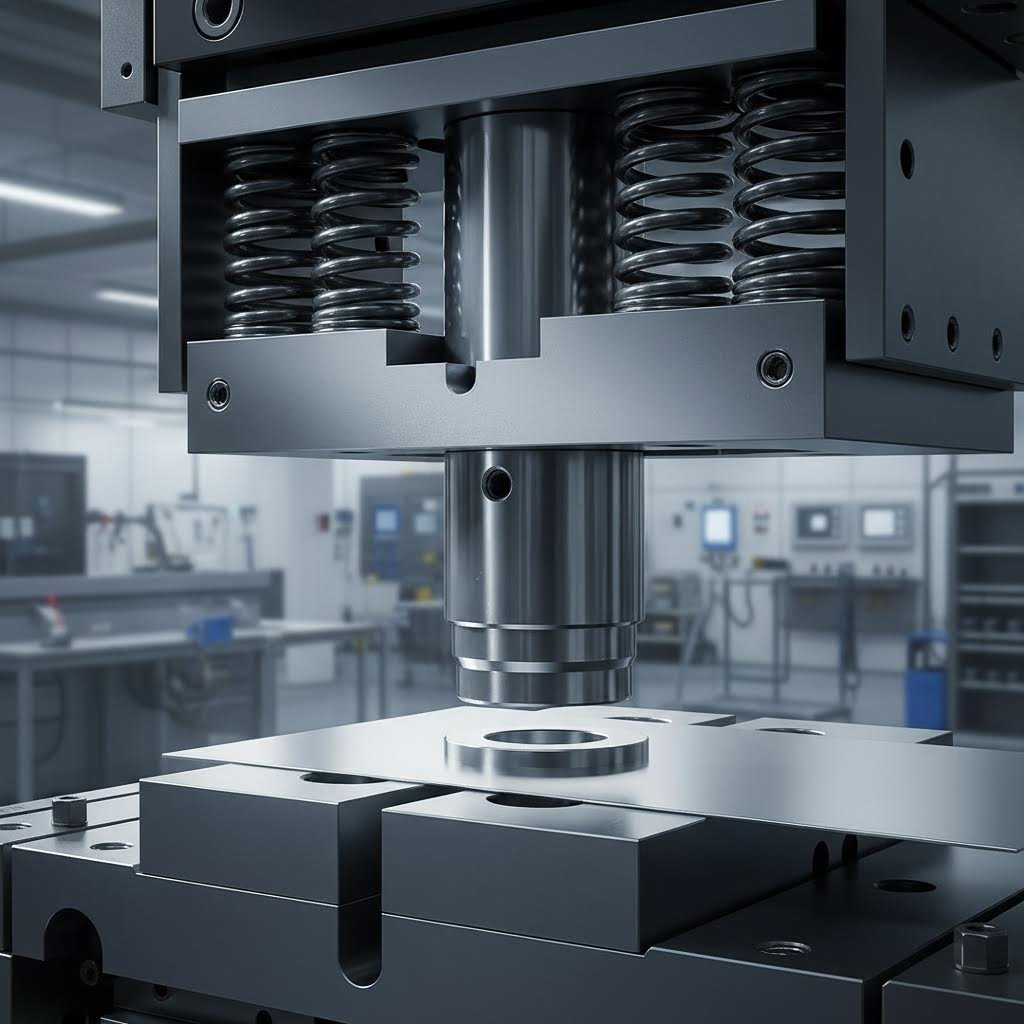
A stripper plate is a precision-machined die component positioned between the punch holder and die block, specifically designed to remove (strip) the workpiece material from the punch after each stamping stroke.
This seemingly simple definition conceals a sophisticated mechanical function that directly impacts your production quality, cycle times, and tooling longevity. Without an effective stripper plate, your stamping operation would face constant interruptions from stuck parts, damaged components, and frustrating downtime.
The Core Mechanical Principle Behind Stripping Action
Imagine punching through a sheet of metal. As the punch descends and penetrates the material, it creates a tight interface between the punch walls and the freshly cut edges. When the punch begins its upward retraction, two forces work against clean separation:
- Friction: The close contact between punch and material creates significant frictional resistance
- Elastic recovery: After deformation, the sheet metal attempts to spring back to its original shape, effectively gripping the punch
The stripper plate counteracts these forces elegantly. As the punch retracts upward, the stripper plate holds the sheet metal firmly down against the die surface. This opposing action cleanly separates the workpiece from the punch, ensuring smooth material release with every stroke. For any tool & die professional, mastering this principle is foundational to die design success.
Why Every Stamping Die Needs Effective Material Release
You'll notice that improper stripping causes a cascade of problems throughout your operation. Parts that cling to punches can become distorted, scratched, or completely destroyed. Worse still, stuck material can cause catastrophic die damage when the next stroke occurs.
Every experienced die maker understands that the stripper plate isn't just about removing parts—it's about maintaining control throughout the entire stamping cycle. An effective stripper plate ensures:
- Consistent part quality across thousands of cycles
- Protection for expensive punch and die components
- Stable material positioning for subsequent operations
- Maximum production speeds without quality compromise
This comprehensive guide consolidates the essential knowledge about stripper plate function in stamping that's typically scattered across multiple resources. Whether you're troubleshooting existing dies or designing new tooling, you'll find the technical depth needed to optimize your operations. Note that some incorrectly search for "tool and dye" information—proper terminology matters when seeking accurate technical guidance in the tool and die industry.
How the Stripper Plate Works Through Each Stamping Cycle
Now that you understand what a stripper plate is and why it matters, let's break down exactly how it functions during each stamping stroke. Understanding this sequence helps you diagnose problems, optimize timing, and appreciate how all die components work together as an integrated system.
The Complete Stamping Stroke Sequence Explained
Think of each stamping cycle as a carefully choreographed dance between multiple components. The stripper plate plays a starring role at a very specific moment—but its positioning and pressure matter throughout the entire sequence. Here's how the complete cycle unfolds:
- Initial Position and Material Feeding: The press ram sits at top dead center. Sheet material advances into position, guided by pilots and stock guides. The stripper plate hovers above the workpiece, ready for engagement.
- Punch Descent and Stripper Contact: As the ram descends, spring-loaded stripper plates contact the material first, applying controlled pressure to hold the sheet firmly against the die surface. This pre-loading prevents material movement during cutting.
- Material Penetration: The punch continues downward through the stripper plate openings. It contacts the sheet metal and begins pushing material into the die opening. At this stage, the yielding force required to initiate deformation depends directly on the material's yield strength.
- Shearing or Forming Action: The punch completes its stroke, either shearing through the material or forming it into the desired shape. During this phase, the workpiece experiences significant stress, and work hardening occurs in the deformation zone.
- Bottom Dead Center: The punch reaches maximum penetration. The cut slug passes through the die opening or the formed feature reaches its final shape. Material stress peaks at this moment.
- Punch Retraction Begins: Here's where the stripper plate truly earns its name. As the punch starts moving upward, the sheet metal's elastic modulus causes it to spring back slightly, gripping the punch walls.
- Stripping Action: The stripper plate maintains downward pressure on the workpiece while the punch continues retracting. This opposing motion cleanly separates the part from the punch. The timing here is critical—too early and the part isn't fully formed, too late and material damage occurs.
- Return to Initial Position: The punch fully retracts through the stripper plate. Material advances for the next cycle. The sequence repeats.
Understanding Material Behavior During Punch Retraction
Why does material cling so stubbornly to the punch during retraction? The answer lies in fundamental material science. When you deform sheet metal beyond its yield stress and yield strength threshold, you permanently change its structure. But elastic recovery—that springback tendency—still occurs in the surrounding material.
During punching, the hole edges experience extreme compression against the punch walls. When the cutting force releases, these edges attempt to recover elastically. Since the punch is still inside the hole, this recovery creates a gripping effect. The tighter the punch-to-die clearance, the more pronounced this phenomenon becomes.
Additionally, work hardening during the stamping process increases the material's yield strength in the deformation zone. This localized strengthening further intensifies the gripping force on the punch. Materials with higher elastic modulus values—like stainless steel compared to aluminum—exhibit stronger springback and require more aggressive stripping action.
The stripper plate must apply sufficient downward force at precisely the right moment to overcome these combined effects. This is why understanding both the yield stress and yield strength characteristics of your workpiece material directly influences stripper plate design decisions.
Component Integration: How Everything Works Together
The stripper plate doesn't operate in isolation. It coordinates with several other die components to ensure successful operation:
- Punches: Must pass freely through stripper plate openings with controlled clearance. Too tight causes binding; too loose allows material pull-up.
- Pilots: These locating pins often extend through the stripper plate, entering pilot holes in the strip before stripping occurs. The stripper plate must accommodate pilot timing perfectly.
- Die Block: Provides the opposing surface that the stripper plate presses material against. Proper alignment between stripper and die ensures even pressure distribution.
- Springs or Pressure Systems: Generate the yielding force that allows the stripper plate to apply consistent pressure regardless of minor thickness variations in the stock material.
When these components work in harmony, you achieve the clean, consistent stripping action that keeps production running smoothly. But what happens when you need to choose between different stripper plate configurations? Let's explore your options in the next section.
Fixed vs Spring-Loaded vs Urethane vs Gas Spring Configurations
Choosing the right stripper plate configuration can make or break your stamping operation. Each type offers distinct advantages depending on your production requirements, material characteristics, and quality expectations. Whether you're running progressive die stampings at high speeds or handling delicate hot dipped galvanized materials that scratch easily, selecting the optimal stripper system directly impacts your bottom line.
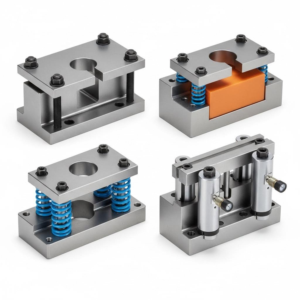
Let's explore the four main configurations you'll encounter in modern stamping operations—and more importantly, when each one makes the most sense for your application.
Fixed Stripper Plates for High-Speed Precision
Fixed stripper plates—also called solid strippers—represent the simplest and most robust configuration available. These plates mount rigidly to the die set without any spring mechanism, maintaining a constant relationship with the punch throughout the stroke.
How does a fixed stripper work? The plate positions just below the punch tips when the die is open. As material feeds into position, it slides between the fixed stripper and die surface. The punch descends through precisely machined holes in the stripper, performs its operation, and retracts. The fixed stripper physically blocks the material from traveling upward with the punch.
You'll find fixed strippers excel in specific scenarios:
- High-speed progressive die tooling: The rigid design eliminates spring oscillation at rapid cycle rates
- Thin materials: No risk of over-compression from excessive spring pressure
- Simple blanking operations: Where material hold-down isn't critical during the cutting stroke
- Applications requiring maximum punch guidance: The fixed relationship provides superior punch support
However, fixed strippers have limitations. They don't apply pressure to hold material flat during forming, and clearance settings are less forgiving of material thickness variations. For progressive stamping dies running hot dip galvanized zinc coating materials with variable coating thickness, this rigidity can become problematic.
Spring-Loaded Systems for Part Protection
Spring-loaded stripper plates—sometimes called floating strippers—add a critical capability: controlled, variable pressure application. Coil springs or die springs mount between the stripper plate and punch holder, allowing the plate to "float" while maintaining consistent downward force.
When the ram descends, the spring-loaded stripper contacts the material first, compressing slightly as it applies holding pressure. This pre-loading keeps the sheet flat against the die surface throughout the punching or forming operation. During retraction, the springs push the stripper plate down, maintaining contact with the workpiece while the punch withdraws.
Spring-loaded configurations shine in these applications:
- Forming operations: Where material must stay flat to prevent wrinkling or distortion
- Variable material thickness: Springs accommodate minor variations without binding
- Cosmetic parts: Controlled pressure minimizes surface marking
- Complex progressive die stampings: Multiple operations benefit from consistent hold-down
The primary consideration with spring-loaded systems involves spring selection and maintenance. Springs fatigue over millions of cycles, and force consistency degrades over time. Regular inspection and replacement scheduling become essential maintenance tasks.
Urethane Stripper Systems: The Versatile Middle Ground
Urethane strippers replace metal springs with polyurethane elastomer pads or buttons. These systems combine aspects of both fixed and spring-loaded designs, offering unique advantages for specific applications.
Urethane provides progressive resistance—the harder you compress it, the more force it generates. This characteristic creates a self-adjusting effect that accommodates material variations while still providing substantial stripping force. Unlike metal springs, urethane won't break suddenly or lose force as dramatically over time.
Consider urethane systems when you need:
- Compact designs: Urethane pads require less vertical space than coil springs
- Moderate stripping forces: Sufficient for most light-to-medium gauge materials
- Reduced maintenance: No individual springs to track and replace
- Cost-effective solutions: Lower initial investment than gas spring systems
The trade-off involves heat sensitivity. Urethane loses resilience at elevated temperatures, making it unsuitable for high-speed operations that generate significant friction heat or applications involving warm forming processes. Additionally, urethane doesn't match the force-per-size capability of gas springs for heavy-duty applications.
Gas Spring Configurations: Maximum Force and Control
Gas springs—also called nitrogen cylinders—represent the premium option for demanding applications. These self-contained units use compressed nitrogen gas to generate consistent, high-force stripping action with precise control.
Unlike mechanical springs that lose force as they compress, gas springs maintain nearly constant pressure throughout their stroke. This characteristic proves invaluable for operations like deep drawing, spin forming, and heavy blanking where consistent force application is critical to part quality.
Gas spring systems deliver advantages that justify their higher cost:
- High force in compact packages: Generate forces mechanical springs can't match in the same space
- Consistent pressure: Nearly flat force curve throughout the stroke
- Long service life: Millions of cycles with minimal force degradation
- Adjustable force: Some designs allow pressure modification for process optimization
The investment consideration matters here. Gas springs cost significantly more than mechanical alternatives and require specialized knowledge for proper sizing and installation. They also need periodic recharging or replacement as nitrogen slowly permeates through seals over extended use.
Comprehensive Configuration Comparison
When evaluating stripper plate options for your progressive die tooling or standalone die applications, this comparison table provides the decision-making data you need:
| Configuration Type | Force Mechanism | Best Applications | Material Thickness Range | Speed Capability | Relative Cost |
|---|---|---|---|---|---|
| Fixed (Solid) | Rigid mounting—no spring action | High-speed blanking, thin materials, maximum punch guidance | 0.005" - 0.060" | Excellent (1000+ SPM) | Low |
| Spring-Loaded | Coil or die springs | Forming operations, variable thickness, cosmetic parts | 0.010" - 0.125" | Good (up to 600 SPM) | Low to Moderate |
| Urethane | Polyurethane elastomer compression | Compact dies, moderate forces, cost-sensitive applications | 0.015" - 0.090" | Moderate (up to 400 SPM) | Low to Moderate |
| Gas Spring | Compressed nitrogen gas | Heavy blanking, deep drawing, spin forming, high-force stripping | 0.030" - 0.250"+ | Good (up to 500 SPM) | High |
Making the Right Selection for Your Application
Your configuration choice ultimately depends on balancing several factors: production speed requirements, material characteristics, part quality expectations, and budget constraints. For high-volume progressive die stampings running at maximum speed, fixed strippers often prove ideal. For operations requiring careful material control—especially when processing hot dipped galvanized steel or other coated materials where surface protection matters—spring-loaded or gas spring systems provide the controlled pressure you need.
Don't overlook the importance of matching your stripper configuration to the specific workpiece material. This connection between stripper design and material properties extends directly into your next critical decision: selecting the right stripper plate material and hardness specification for long-term performance.
Material Selection and Hardness Requirements for Stripper Plates
You've selected the right stripper plate configuration—but have you considered what it's actually made of? The material you choose for your stripper plate directly impacts wear resistance, service life, and ultimately your cost-per-part. Selecting inappropriate tool steel grades leads to premature wear, unexpected downtime, and compromised part quality. Understanding material selection criteria helps you make informed decisions that pay dividends across millions of stamping cycles.
Tool Steel Selection for Optimal Wear Resistance
Stripper plates endure constant abrasive contact with sheet metal, repeated impact loading, and significant compressive forces. These demanding conditions require tool steels specifically engineered for wear resistance and toughness. Three steel grades dominate stripper plate applications: D2, A2, and O1—each offering distinct performance characteristics.
D2 Tool Steel: This high-carbon, high-chromium steel represents the premium choice for most stripper plate applications. With chromium content around 12%, D2 offers exceptional wear resistance and maintains hardness at elevated temperatures. You'll find D2 particularly valuable when stamping abrasive materials or running extended production campaigns. Some manufacturers specify Japanese D2 tool steel powdered version for applications demanding superior uniformity and enhanced toughness beyond conventional D2.
A2 Tool Steel: When you need a balance between wear resistance and toughness, A2 delivers. This air-hardening steel offers better impact resistance than D2 while still providing respectable wear performance. A2 machines more easily than D2 and exhibits less distortion during heat treatment—advantages that translate to lower manufacturing costs.
O1 Tool Steel: This oil-hardening tool steel represents the economical option for less demanding applications. O1 machines exceptionally well and achieves good hardness, but its wear resistance falls short of D2 and A2. Consider O1 for prototype tooling, short-run production, or applications stamping soft materials like aluminum alloys.
The steel modulus of elasticity also factors into your selection. Stripper plates must maintain dimensional stability under repeated loading cycles. All three common tool steels share similar elastic modulus values around 30 million psi, but their fatigue resistance and wear characteristics differ significantly based on composition and heat treatment.
Hardness Requirements and Heat Treatment
Achieving proper hardness is non-negotiable for stripper plate performance. Working surfaces typically require hardness values between 58-62 HRC (Rockwell C scale) to resist wear from constant material contact. But here's something many engineers overlook: hardness alone doesn't guarantee performance.
Consider these hardness guidelines for different applications:
- High-volume production (1M+ parts): Target 60-62 HRC for maximum wear life
- Standard production runs: 58-60 HRC provides good balance of wear resistance and toughness
- Impact-prone applications: Consider 56-58 HRC to reduce chipping risk
- Prototype or short-run tooling: 54-58 HRC often suffices
Heat treatment quality matters as much as the target hardness number. Improper heat treatment creates soft spots, internal stresses, or brittle zones that lead to premature failure. Always verify hardness at multiple locations on finished stripper plates and request heat treatment certifications from your supplier.
Matching Stripper Plate Material to Your Workpiece
Here's where material selection becomes application-specific. The workpiece you're stamping directly influences stripper plate wear patterns and longevity. Different materials present vastly different challenges:
Stamping Aluminum Alloys: Aluminum's softness seems like it would be easy on tooling, but appearances deceive. Aluminum tends to gall—transferring material onto tool surfaces through adhesive wear. This buildup creates surface irregularities that mark parts and accelerate further wear. For aluminum alloys, polished stripper plate surfaces and sometimes specialized coatings outperform raw tool steel. O1 or A2 at moderate hardness often suffices since abrasive wear remains minimal.
Stamping Mild Steel: Standard carbon steels present moderate wear challenges. D2 at 58-60 HRC handles most mild steel applications effectively. Material thickness becomes the primary consideration—thicker stock generates higher stripping forces and accelerates wear on punch hole edges.
Stamping Stainless Steel: Stainless steel's strain hardening and work hardening characteristics create particularly demanding conditions. As you punch through stainless, the deformation zone work hardens significantly, increasing local hardness and abrasiveness. This phenomenon accelerates stripper plate wear compared to equivalent-thickness mild steel. Specify D2 at maximum practical hardness (60-62 HRC) for stainless steel applications.
Stamping High-Strength Steels: Advanced high-strength steels (AHSS) and ultra-high-strength steels used in automotive applications push tooling to its limits. These materials exhibit extreme strain hardening and work hardening behavior, with localized hardness sometimes exceeding the original stripper plate surface. Consider specialized tool steels or surface treatments for these demanding applications.
Tool Steel Comparison for Stripper Plate Applications
This comparison helps you match tool steel grades to your specific requirements:
| Tool Steel Grade | Typical Hardness (HRC) | Wear Resistance | Toughness | Machinability | Recommended Applications |
|---|---|---|---|---|---|
| D2 | 58-62 | Excellent | Moderate | Difficult | High-volume production, abrasive materials, stainless steel stamping |
| A2 | 57-62 | Good | Good | Moderate | General purpose, impact-prone applications, balanced performance needs |
| O1 | 57-61 | Fair | Good | Excellent | Short runs, prototypes, aluminum alloys, cost-sensitive applications |
| S7 | 54-58 | Fair | Excellent | Good | High-impact applications, shock loading conditions |
| M2 (HSS) | 60-65 | Excellent | Moderate | Difficult | Extreme wear conditions, high-speed operations |
How Material Thickness Affects Stripper Plate Specifications
Thicker workpiece materials demand more robust stripper plates. As material thickness increases, so do the forces involved in stripping. Consider these relationships:
- Light gauge (under 0.030"): Standard tool steel grades at moderate hardness perform well. Focus on surface finish quality to prevent marking.
- Medium gauge (0.030" - 0.090"): D2 or A2 at 58-60 HRC recommended. Pay attention to punch hole clearances as stripping forces increase.
- Heavy gauge (0.090" - 0.187"): Specify D2 at 60-62 HRC minimum. Consider larger clearances and reinforced stripper plate thickness.
- Plate stock (over 0.187"): Premium tool steels essential. Evaluate surface treatments like nitriding or PVD coatings for extended life.
Remember that thicker materials experience more pronounced strain hardening during the punching process. This work hardening effect means the material actively becomes harder and more abrasive as you stamp it—explaining why heavy-gauge stamping wears stripper plates faster than thickness alone would suggest.
With your stripper plate material properly specified, the next critical step involves calculating the force requirements and dimensional tolerances that ensure reliable performance throughout your production run.
Design Specifications and Force Calculations
You've selected the right stripper plate material—but how do you know if it's properly sized and configured for your application? Getting the design specifications right separates reliable tooling from problem-prone dies. The calculations and tolerances covered here form the engineering foundation that ensures your stripper plate performs consistently across millions of cycles.
Calculating Required Stripping Force for Your Application
How much force does your stripper plate actually need to generate? This fundamental question drives spring selection, gas cylinder sizing, and overall die design. The answer connects directly to your punching force and material characteristics.
As a practical starting point, stripping force typically needs to fall between 10-20% of your total punching force. This range accounts for the friction and elastic recovery forces that cause material to cling to the punch. However, several factors push requirements toward either end of this spectrum:
- Material type: Stainless steel and high-strength materials require forces toward the 20% range due to pronounced springback. Softer aluminum alloys often strip cleanly at 10% or below.
- Punch-to-die clearance: Tighter clearances increase material grip on the punch, demanding higher stripping forces.
- Hole geometry: Complex shapes with irregular perimeters create more surface contact and require additional stripping force.
- Material thickness: Thicker stock generates proportionally higher stripping resistance.
- Surface finish: Rougher punch surfaces increase friction, raising force requirements.
The punching force itself depends on the yield stress of steel or whatever material you're cutting. For blanking and punching operations, you can estimate this force using the formula: Punching Force = Perimeter × Material Thickness × Shear Strength. Since shear strength typically equals 60-80% of the material's yield strength of steel (or other workpiece material), you can derive reasonable estimates from published material specifications.
Consider this example: You're punching a 1-inch diameter hole through 0.060" mild steel with a shear strength of 40,000 psi. The punching force calculates as: 3.14 inches (perimeter) × 0.060 inches × 40,000 psi = approximately 7,540 pounds. Your stripping force requirement falls between 754 and 1,508 pounds (10-20% of punching force).
Understanding the relationship between tensile strength vs yield strength helps refine these calculations. While tensile strength represents the maximum stress before failure, yield stress indicates when permanent deformation begins—the threshold that matters for stripping force estimation. The yielding load your stripper system must overcome correlates directly with these material properties.
Critical Clearance and Tolerance Specifications
The clearance between stripper plate holes and punches might seem like a minor detail, but improper tolerances cause major headaches. Too tight, and punches bind or wear prematurely. Too loose, and material pulls up into the gap, creating burrs and quality defects.
Industry practice establishes clearance tolerances between stripper plate holes and punches at 0.001-0.003 inches per side. This specification means a 0.500" diameter punch requires a stripper plate hole between 0.502" and 0.506" diameter. Where you fall within this range depends on your specific application:
- Precision blanking (0.001" per side): Provides maximum punch guidance and support. Best for thin materials and high-precision requirements. Demands excellent alignment and minimal thermal expansion.
- General stamping (0.0015-0.002" per side): Balances guidance with operational forgiveness. Accommodates normal thermal variation and minor alignment imperfections.
- Heavy-duty applications (0.002-0.003" per side): Allows for greater thermal expansion and potential misalignment. Reduces binding risk but sacrifices some punch support.
The elastic modulus of steel—both the stripper plate and workpiece—influences how these clearances perform under load. Materials with higher modulus of elasticity of steel values deflect less under equivalent forces, meaning clearance specifications can run tighter without binding issues. The elastic modulus of steel hovers around 29-30 million psi, providing the baseline for most calculations.
Key Design Parameters Checklist
When specifying stripper plate dimensions and performance requirements, ensure you've addressed each of these critical parameters:
- Stripping force requirement: Calculate based on 10-20% of punching force, adjusted for material and geometry factors
- Punch hole clearance: Specify 0.001-0.003" per side based on application precision requirements
- Plate thickness: Typically 0.75-1.5× the punch diameter for adequate rigidity; thicker for heavy-duty applications
- Material specification: Define tool steel grade, hardness range, and any surface treatment requirements
- Spring or gas cylinder sizing: Match force output to calculated stripping requirements with appropriate safety margin
- Travel distance: Ensure sufficient stripper travel to accommodate material thickness plus clearance for strip advancement
- Mounting provisions: Specify bolt patterns, dowel locations, and alignment features
- Surface finish: Define bottom surface finish requirements (typically 32 microinch Ra or better for cosmetic applications)
Thickness Considerations for Structural Rigidity
Stripper plate thickness isn't arbitrary—it directly affects operational stability and longevity. An undersized plate flexes under stripping loads, causing uneven material release and accelerated wear. Oversized plates waste material and add unnecessary die weight.
For most applications, stripper plate thickness should equal 0.75 to 1.5 times the largest punch diameter in the die. This guideline ensures adequate rigidity while keeping weight manageable. Consider these adjustments:
- Increase thickness when working with heavy-gauge materials, using gas springs with high preload forces, or spanning long unsupported distances between mounting points
- Decrease thickness for compact die designs, light-gauge materials, or when die weight constraints apply
The yield stress of steel used in your stripper plate determines how much load it can handle before permanent deformation occurs. Harder tool steels offer higher yield strength of steel values, allowing thinner sections to carry equivalent loads. However, remember that increased hardness reduces toughness—a balance must be struck based on your specific loading conditions.
With force requirements calculated and tolerances specified, you're ready to apply these principles to the unique challenges of progressive die systems—where stripper plate function becomes significantly more complex.
Stripper Plate Function in Progressive Die Systems
Progressive dies present a unique engineering challenge: multiple operations occurring simultaneously across different stations, all relying on a single stripper plate to maintain control. Unlike standalone dies where you're managing one punch and one operation, progressive die components must work in perfect coordination—and the stripper plate sits at the center of this orchestration.
When you're running a die in progressive mode, the stripper plate doesn't just strip material from one punch. It manages varying punch sizes, different operation types, and critical timing relationships across every station. Getting this right means the difference between consistent first-pass approval rates and frustrating quality escapes that halt production.
Multi-Station Stripping Challenges in Progressive Dies
Imagine a ten-station progressive die producing an automotive bracket. Station one might pierce small pilot holes, station three blanks a large opening, station six performs a deep form, and station ten cuts off the finished part. Each station presents different stripping demands—yet one stripper plate must handle them all simultaneously.
What makes this so challenging? Consider these factors unique to progressive tooling:
- Variable punch sizes: Small piercing punches require different clearances than large blanking punches. The stripper plate must accommodate both without compromising guidance for either.
- Mixed operation types: Piercing, blanking, forming, and embossing operations each create different material-to-punch interactions. Forming stations may need holding pressure while piercing stations primarily need clean stripping action.
- Cumulative strip distortion: As the strip advances through stations, prior operations create stress patterns that affect material behavior. Work hardening from earlier stations influences stripping characteristics at later stations.
- Station-to-station force variation: Stripping force requirements differ dramatically between a 0.125" diameter pilot hole and a 2" square blank. The stripper plate spring system must balance these competing demands.
- Timing synchronization: All stations must strip simultaneously as the ram retracts. Uneven stripping action causes strip misalignment that cascades through subsequent stations.
Materials like high-strength steel—which exhibit pronounced yield point for steel characteristics—amplify these challenges. The localized hardening around pierced holes at early stations affects how material behaves during forming operations downstream.
Coordinating Stripper Action with Pilots and Lifters
Progressive die operation depends on precise strip positioning at every stroke. Two critical systems interact directly with the stripper plate: pilot pins and stock lifters. Understanding these relationships helps you design stripper plates that support—rather than fight—accurate strip advancement.
Pilot Pin Coordination: Pilot pins locate the strip precisely before any punches engage the material. In most progressive dies, pilots extend through the stripper plate and enter previously pierced holes in the strip before the stripper plate contacts the material surface. This sequence ensures accurate positioning before hold-down pressure applies.
Your stripper plate design must account for pilot timing by providing:
- Sufficient pilot clearance holes—typically 0.003-0.005" larger than pilot diameter per side
- Adequate stripper travel to allow pilots to fully engage before material contact
- Proper spring preload that doesn't resist pilot entry into strip holes
Stock Lifter Integration: Stock lifters raise the strip between press strokes, allowing material to advance to the next station. The stripper plate must release cleanly and quickly enough for lifters to function—any delayed stripping action causes feed timing problems.
When coordinating with lifters, consider:
- Stripper plate return speed must exceed lifter actuation timing
- No interference between stripper plate edges and lifter components
- Consistent stripping force that doesn't vary with lifter position
Maintaining Strip Flatness Between Stations
One often-overlooked stripper plate function in progressive dies involves maintaining strip flatness as material moves through stations. Warped or buckled strip causes misfeeds, quality defects, and potential die damage.
The stripper plate contributes to strip flatness by applying uniform pressure across the strip width during each stroke. This controlled compression flattens minor material variations and stress-induced distortions. For materials near their yield point for steel threshold, this flattening action can actually improve part quality by relieving residual stresses.
Effective flatness control requires:
- Uniform spring pressure distribution across the stripper plate surface
- Sufficient stripper plate rigidity to prevent flexing under load
- Proper stripper-to-die parallelism within 0.001" across the plate length
- Adequate dwell time at bottom dead center for material to settle
Key Considerations for Progressive Die Stripper Plates
When designing or specifying stripper plates for progressive die applications, address these critical factors:
- Spring force balancing: Calculate total stripping force requirements by summing individual station needs, then distribute springs to achieve uniform pressure. Avoid concentrating all spring force near one end of the plate.
- Clearance standardization: Where possible, standardize punch hole clearances to simplify manufacturing and replacement. Group similar-sized punches in adjacent stations.
- Sectional stripper design: For complex dies, consider sectional stripper plates that allow individual station adjustment without removing the entire assembly.
- Wear monitoring provisions: Include inspection windows or removable sections that allow wear assessment at critical stations without full die disassembly.
- Thermal expansion accommodation: Long stripper plates spanning many stations may require expansion relief features to prevent binding as die temperature rises during production.
- Pilot timing verification: Design stripper travel to ensure pilots engage a minimum of two material thicknesses before stripper contact occurs.
Impact on Production Quality and Approval Rates
In high-volume automotive and precision applications, stripper plate performance directly influences your first-pass approval rates. Progressive tooling running thousands of parts per hour cannot tolerate inconsistent stripping—every quality escape represents rework, scrap, or worse, a defective part reaching the customer.
Proper stripper plate function in progressive die systems delivers measurable benefits:
- Consistent hole positioning across all stations
- Uniform part dimensions from first piece to last
- Reduced surface marking and cosmetic defects
- Extended die life through controlled material handling
- Higher sustainable production speeds without quality degradation
When your progressive die stripper plate works correctly, you'll notice fewer interruptions, more consistent measurements, and higher confidence in your production quality. When it doesn't, the problems compound rapidly—mislocated features, stuck parts, and damaged tooling that brings production to a halt.
Of course, even the best-designed stripper plate eventually encounters problems. Knowing how to diagnose and resolve common issues keeps your progressive dies running at peak performance—which brings us to practical troubleshooting strategies.
Troubleshooting Common Stripper Plate Problems
Even perfectly designed stripper plates eventually develop issues—and when they do, production grinds to a halt while you scramble to identify the root cause. The frustrating reality? Many stripper plate problems share similar symptoms but require completely different solutions. Knowing how to quickly diagnose and resolve these issues separates experienced toolmakers from those stuck in endless trial-and-error cycles.
Let's walk through the most common problems you'll encounter, connecting each issue back to the mechanical principles we've already covered. Understanding why problems occur makes fixing them—and preventing recurrence—far more straightforward.
Diagnosing Slug Pulling and Retention Issues
Slug pulling ranks among the most dangerous stripper plate problems you'll face. When slugs stick to the punch and pull back through the stripper plate, they can cause catastrophic die damage on the next stroke. Even worse, these errant slugs create safety hazards for operators.
What causes slugs to follow the punch upward instead of dropping cleanly through the die? Several factors contribute:
- Insufficient die clearance: When punch-to-die clearance runs too tight, the shearing action creates a polished slug edge that grips the punch tightly. The relationship between yield strength vs tensile strength matters here—materials with higher elongation percentages tend to grip more aggressively.
- Vacuum effect: As the punch retracts rapidly, it creates a partial vacuum beneath the slug. Without proper venting or vacuum relief features, this suction overcomes gravity and pulls slugs upward.
- Magnetism: Ferrous materials can magnetize during repeated stamping cycles. This residual magnetism attracts slugs to punch faces.
- Punch surface condition: Worn or damaged punch faces with rough surfaces increase friction, holding slugs tighter.
- Inadequate stripping force: Remember those force calculations from earlier? Insufficient stripping pressure allows material—including slugs—to travel with the retracting punch.
Solutions vary by root cause. For vacuum-related issues, add vacuum relief grooves to punch faces or small vent holes through the die block. Demagnetizing punches periodically addresses magnetic retention. Increasing stripper force through spring replacement or pressure adjustment handles grip-related problems. When elongation characteristics of your material contribute to excessive slug grip, consider adjusting die clearance to optimize the shear-versus-fracture ratio.
Solving Material Marking and Surface Quality Problems
Surface marks, scratches, and witness lines on finished parts often trace directly back to stripper plate issues. For cosmetic components or parts requiring secondary finishing, these defects mean scrapped material and frustrated customers.
Material marking typically occurs when:
- Excessive stripper pressure: Over-compression leaves witness marks matching stripper plate surface imperfections
- Rough stripper surface finish: Machining marks or wear patterns transfer to workpiece surfaces
- Debris accumulation: Metal chips, lubricant residue, or foreign particles trapped between stripper and material create localized pressure points
- Misalignment: Uneven stripper contact causes concentrated pressure zones that mark parts
When deformation hardening occurs during stamping, material becomes more susceptible to surface marking. The work-hardened zones around pierced holes or formed features show marks more readily than virgin material. This phenomenon explains why marking problems sometimes appear only at specific part locations.
Address marking issues by polishing stripper plate contact surfaces to 16 microinch Ra or better. Verify spring force calculations haven't resulted in excessive pressure—remember, more force isn't always better. Implement regular cleaning protocols to prevent debris buildup, and check stripper-to-die parallelism if marking appears uneven across the part.
Comprehensive Stripper Plate Troubleshooting Guide
This reference table consolidates the most common problems you'll encounter, helping you quickly identify root causes and implement effective solutions:
| Problem | Symptoms | Common Causes | Solutions |
|---|---|---|---|
| Slug Pulling | Slugs found on die surface or in stripper area; double-hits on parts; die damage | Vacuum effect; magnetism; tight die clearance; worn punch faces; low stripper force | Add vacuum relief features; demagnetize tooling; adjust clearances; resurface punches; increase spring force |
| Material Marking/Scratching | Witness lines on parts; surface scratches; pressure marks matching stripper features | Excessive pressure; rough stripper surface; debris accumulation; misalignment | Reduce spring preload; polish contact surfaces; implement cleaning schedule; verify parallelism |
| Uneven Stripping | Parts cock or tilt during stripping; localized material pull-up; inconsistent part dimensions | Unbalanced spring distribution; worn springs; unequal punch lengths; stripper plate warpage | Redistribute or replace springs; verify punch heights; resurface or replace stripper plate |
| Premature Wear | Enlarged punch holes; visible wear patterns; increased burr formation; declining part quality | Inadequate hardness; abrasive workpiece material; insufficient lubrication; misalignment causing galling | Upgrade tool steel grade; increase hardness specification; improve lubrication; correct alignment issues |
| Part Distortion | Warped or bent parts; dimensional variation; flatness problems | Insufficient hold-down pressure; delayed stripping timing; uneven force distribution | Increase stripper force; adjust timing relationship; balance spring placement |
| Punch Binding | Punches stick in stripper; galling on punch surfaces; increased press load | Insufficient clearance; thermal expansion; misalignment; burr buildup in holes | Open clearances per specifications; allow thermal stabilization; realign components; deburr holes |
| Inconsistent Stripping Force | Variable part quality; intermittent problems; force readings fluctuate | Fatigued springs; contaminated gas cylinders; urethane degradation; loose mounting | Replace springs on schedule; service gas cylinders; replace urethane components; verify all fasteners |
Connecting Problems to Mechanical Principles
Notice how many troubleshooting solutions circle back to the fundamentals we've discussed? Insufficient stripping force relates directly to those spring selection and force calculations—if you sized springs based on 10% of punching force but your material's yield strength vs tensile strength ratio runs higher than typical, you may need to target the upper 20% threshold instead.
Similarly, premature wear issues connect to material selection decisions. When stamping materials that exhibit significant deformation hardening, standard O1 tool steel at moderate hardness simply won't last. The formability limit diagram for your workpiece material influences not just part design but stripper plate wear patterns as well.
Uneven stripping problems often stem from inadequate attention to spring placement during design. Distributing springs uniformly across the stripper plate sounds obvious, but complex die layouts sometimes force compromises. When troubleshooting reveals uneven stripping, revisiting spring distribution—and potentially adding supplemental springs in problem areas—frequently resolves the issue.
Preventing Recurrence Through Root Cause Analysis
Quick fixes get production running, but they don't prevent problems from returning. For each issue you resolve, ask: what allowed this condition to develop? Tapered cutting edges on punches, for example, might temporarily solve slug pulling—but if the underlying vacuum issue remains unaddressed, problems will resurface when punches wear past their tapered zone.
Document your troubleshooting findings and solutions. Track which dies experience recurring issues and correlate problems with specific materials, production volumes, or operating conditions. This data reveals patterns that point toward systemic improvements rather than repeated Band-Aid fixes.
Materials with higher elongation values and pronounced work hardening characteristics—like stainless steels and some aluminum alloys—consistently challenge stripper plate systems more than mild steel. If your production mix includes these materials, proactive stripper plate upgrades often cost less than reactive troubleshooting over time.
Of course, even the best troubleshooting skills can't fix problems that proper maintenance would have prevented. Establishing robust inspection and maintenance procedures keeps small issues from becoming production-stopping failures.
Maintenance Procedures and Inspection Criteria
Troubleshooting solves immediate problems—but wouldn't you rather prevent them entirely? Consistent maintenance and systematic inspection keep your stripper plates performing reliably across millions of cycles. The difference between reactive firefighting and proactive prevention often comes down to a few minutes of regular attention that saves hours of unplanned downtime.
Understanding elastic modulus metals behavior helps explain why maintenance matters so much. Tool steels maintain their stiffness characteristics throughout their service life—until localized wear, fatigue cracks, or surface degradation compromise that consistency. By the time you notice quality problems, significant damage has already occurred. Catching issues early through systematic inspection prevents cascading failures that damage expensive die components.
Essential Inspection Points for Stripper Plate Longevity
What should you actually look for during stripper plate inspections? Focus your attention on these critical areas where problems develop first:
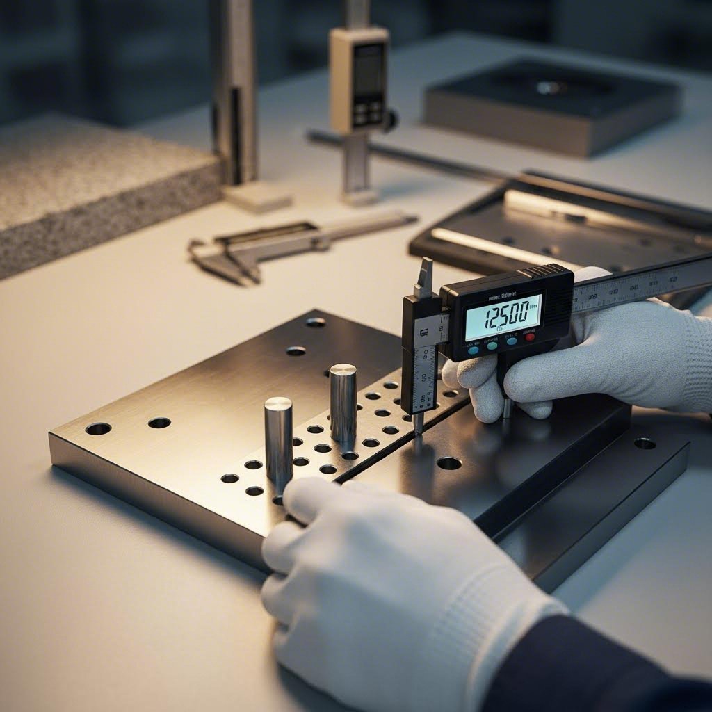
Punch Hole Condition: Examine every punch hole for signs of wear, galling, or enlargement. Use calibrated pin gauges to verify clearances remain within specification—typically 0.001-0.003" per side as discussed earlier. Worn holes allow material pull-up and reduce punch guidance, accelerating wear on both components. Pay particular attention to holes serving high-wear stations like blanking operations on abrasive materials.
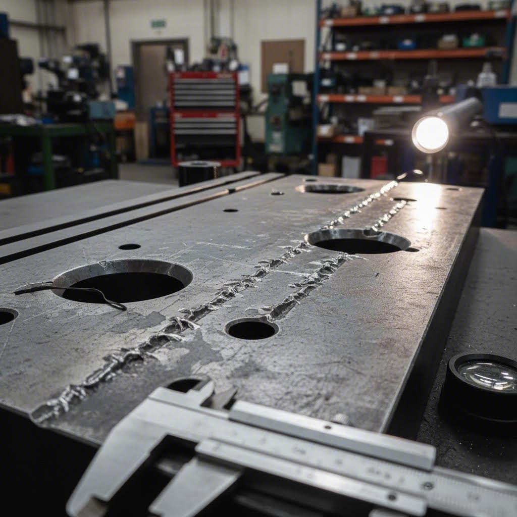
Surface Condition: Inspect the stripper plate bottom surface for scratches, gouges, or embedded debris. These imperfections transfer directly to your parts as witness marks. Check for galling patterns that indicate misalignment or insufficient lubrication. Materials with high yield strain steel characteristics—like stainless and high-strength steels—tend to cause more aggressive surface wear than mild steel.
Spring Force Consistency: Test spring forces using a force gauge at multiple locations across the stripper plate. Force variation exceeding 10% between springs indicates replacement need. For gas spring systems, verify pressure readings fall within manufacturer specifications. Degraded springs cause uneven stripping that produces dimensional variation and quality defects.
Crack Detection: Examine stressed areas—particularly around punch holes and mounting bolt locations—for fatigue cracks. Use dye penetrant inspection for critical applications or when visual inspection proves inconclusive. Small cracks propagate rapidly under repeated loading, leading to catastrophic plate failure.
Parallelism and Flatness: Measure stripper plate flatness across its length using precision straightedges or coordinate measuring equipment. Warped plates cause uneven material contact and inconsistent stripping. The modulus of steel ensures plates maintain their shape under normal loading—deviation indicates overloading, improper heat treatment, or accumulated stress damage.
Maintenance Interval Guidelines
How often should you inspect stripper plates? The answer depends on your production volume, workpiece material, and quality requirements. These guidelines provide starting points—adjust based on your specific experience:
- High-volume production (100,000+ parts/week): Visual inspection every shift; detailed measurement inspection weekly; comprehensive evaluation monthly
- Medium-volume production (25,000-100,000 parts/week): Visual inspection daily; detailed measurement inspection bi-weekly; comprehensive evaluation quarterly
- Low-volume or prototype production: Visual inspection before each production run; detailed measurement inspection monthly; comprehensive evaluation annually
Workpiece material significantly influences maintenance frequency. Stamping stainless steel, high-strength steel, or abrasive coated materials accelerates wear—consider doubling inspection frequency compared to mild steel applications. The tensile modulus steel characteristics of your workpiece affect how aggressively material interacts with stripper plate surfaces.
Stripper Plate Maintenance Checklist
Use this comprehensive checklist during your inspection routines:
- Verify all punch hole diameters remain within clearance specifications using calibrated gauges
- Check for galling, scoring, or material buildup in punch holes
- Inspect bottom contact surface for scratches, gouges, or embedded debris
- Test spring force at each spring location—replace any showing greater than 10% force loss
- Examine gas cylinders for leakage, proper pressure, and smooth operation
- Check urethane components for compression set, cracking, or heat damage
- Verify mounting bolt torque meets specifications
- Inspect for cracks at stress concentration points
- Measure overall flatness and parallelism to die surface
- Document all measurements and compare against baseline specifications
- Clean all surfaces and apply appropriate lubricants per maintenance schedule
- Verify proper alignment with punches and die block
When to Refurbish vs Replace Your Stripper Plates
Not every worn stripper plate needs replacement—refurbishment often restores performance at a fraction of replacement cost. But knowing when each option makes sense saves both money and frustration.
Refurbishment candidates:
- Surface scratches or wear that doesn't exceed 0.005" depth
- Punch holes worn within 0.002" of maximum allowable clearance
- Minor galling that responds to polishing
- Flatness deviation under 0.003" that grinding can correct
Replacement indicators:
- Visible cracks at any location—cracks cannot be reliably repaired
- Punch holes worn beyond maximum clearance specifications
- Severe galling or material transfer that polishing cannot remove
- Warpage exceeding 0.005" that grinding would reduce plate thickness below minimum
- Multiple worn areas suggesting overall material fatigue
- Heat damage from excessive friction or improper lubrication
When calculating refurbishment versus replacement economics, factor in not just direct costs but also risk. A refurbished plate that fails during production costs far more than the savings achieved—including lost production time, potential die damage, and quality escapes.
Proper maintenance directly impacts both part quality and die longevity. A well-maintained stripper plate delivers consistent performance across its full service life, while neglected plates create quality problems that compound over time. The few minutes invested in regular inspection pay dividends in reduced scrap, fewer production interruptions, and extended tooling life.
With maintenance protocols established, you're ready to consider how advanced engineering approaches—including simulation and expert die design partnerships—can optimize stripper plate performance before production even begins.

Optimizing Stripper Plate Performance for Production Excellence
You've now explored the complete picture of stripper plate function in stamping—from fundamental mechanics through material selection, design calculations, progressive die applications, troubleshooting, and maintenance. But here's the real question: how do you bring all this knowledge together to achieve production excellence in your specific application?
The answer lies in two connected strategies: applying systematic optimization principles and partnering with die makers who possess the advanced capabilities needed for demanding applications. Let's consolidate what you've learned and explore how modern engineering approaches eliminate guesswork from stripper plate design.
Leveraging Simulation for Optimized Stripper Plate Design
Traditional die development relied heavily on trial-and-error. You'd build tooling based on experience and calculations, run test parts, identify problems, modify the die, and repeat until results met specifications. This approach works—but it's expensive, time-consuming, and frustrating when dealing with complex applications or demanding materials.
Computer-Aided Engineering (CAE) simulation transforms this paradigm. Modern simulation tools predict stripper plate performance before any steel gets cut. By modeling material behavior, force interactions, and timing relationships digitally, engineers identify potential problems during design rather than during expensive production trials.
What can simulation reveal about stripper plate performance?
- Force distribution analysis: Visualize how stripping forces distribute across the plate surface, identifying areas needing additional spring support or reinforcement
- Material flow prediction: Understand how workpiece material behaves during stripping, predicting potential marking, distortion, or retention issues
- Timing optimization: Model the precise sequence of pilot engagement, stripper contact, and punch retraction to ensure proper coordination
- Deflection analysis: Calculate stripper plate deflection under load, verifying thickness specifications provide adequate rigidity
- Thermal effects: Predict temperature rise during high-speed production and its impact on clearances and material properties
Understanding what yield strength means for your specific workpiece material becomes crucial during simulation setup. Engineers input material properties—including yield strength, young's modulus of steel values, and elongation characteristics—to create accurate models. For aluminum applications, the modulus of elasticity of aluminum (approximately 10 million psi, compared to steel's 29-30 million psi) significantly affects springback behavior and stripping force requirements.
The simulation advantage extends beyond initial design. When problems arise during production, CAE analysis helps identify root causes without destructive testing or extended trial runs. This capability proves especially valuable for yield in engineering applications where material behavior near the elastic limit directly influences stripping characteristics.
Partnering with Experienced Die Makers for Complex Applications
Even with comprehensive knowledge, some applications demand expertise beyond in-house capabilities. Complex progressive dies, tight-tolerance automotive components, and high-volume production tooling benefit from partnership with specialized die makers who invest in advanced design and manufacturing capabilities.
What should you look for when selecting a die partner for demanding applications?
- Quality system certification: IATF 16949 certification demonstrates commitment to automotive-grade quality management systems
- Simulation capabilities: In-house CAE simulation for predicting and optimizing die performance before production
- Rapid prototyping: Ability to deliver prototype tooling quickly for validation before full production investment
- First-pass approval rates: Track record of delivering tooling that meets specifications without extensive modification cycles
- Technical depth: Engineering team that understands material science, including concepts like young's modulus of steel and their practical implications
Consider how these capabilities translate to real-world results. Manufacturers like Shaoyi exemplify this integrated approach—their IATF 16949-certified operations combine advanced CAE simulation with precision manufacturing to optimize all die components including stripper plates. Their rapid prototyping capabilities deliver functional tooling in as little as 5 days, enabling fast validation cycles. Perhaps most tellingly, their 93% first-pass approval rate demonstrates that simulation-driven design actually delivers defect-free results in production.
For automotive and OEM applications where quality requirements leave no room for compromise, exploring comprehensive mold design and fabrication capabilities from experienced partners often proves more cost-effective than extended in-house development cycles. The investment in proper engineering upfront prevents the exponentially higher costs of production problems, quality escapes, and tooling modifications.
Key Selection Criteria Summary
As you apply what you've learned about stripper plate function in stamping, keep these consolidated selection criteria in mind:
- Configuration: Match fixed, spring-loaded, urethane, or gas spring systems to your speed requirements, material characteristics, and quality expectations
- Material: Select tool steel grades and hardness specifications appropriate for your workpiece material and production volume—D2 at 60-62 HRC for demanding applications, A2 or O1 for less aggressive requirements
- Force calculations: Size spring or gas cylinder systems for 10-20% of punching force, adjusted for material properties and geometry
- Clearances: Specify punch hole clearances at 0.001-0.003" per side based on precision requirements and thermal considerations
- Thickness: Design for 0.75-1.5× largest punch diameter to ensure adequate rigidity under stripping loads
- Maintenance planning: Establish inspection intervals appropriate for production volume and material abrasiveness
Understanding what yield strength means for both your stripper plate material and workpiece enables informed decisions throughout the selection process. The relationship between material properties, force requirements, and wear characteristics determines long-term tooling success.
Moving Forward with Confidence
Stripper plate function in stamping may seem like a narrow technical topic—but as you've discovered, it connects to nearly every aspect of die design and production quality. From the fundamental physics of elastic recovery through advanced simulation optimization, mastering stripper plate design delivers measurable improvements in quality, productivity, and tooling longevity.
Whether you're troubleshooting existing dies or specifying new tooling, the principles covered here provide the foundation for confident decision-making. Combine this knowledge with advanced engineering capabilities—whether developed in-house or accessed through experienced die partners—and you'll achieve the consistent, high-quality stamping results that drive manufacturing success.
The next time parts stick to your punches or quality issues trace back to stripping problems, you'll know exactly where to look and what to do about it. That's the practical value of truly understanding how this critical die component works.
Frequently Asked Questions About Stripper Plate Function in Stamping
1. What is the function of a stripper plate in a stamping die?
A stripper plate serves multiple critical functions in stamping operations. It holds the metal firmly against the die during cutting or piercing to prevent material movement and distortion. Most importantly, it strips the workpiece from the punch during the return stroke by applying downward force that counteracts friction and elastic recovery forces. This ensures clean material release, protects both the punch and workpiece from damage, and enables consistent high-speed production cycles.
2. What is stripping force in a press tool?
Stripping force is the force required to separate the stamped material from the punch after the cutting or forming operation. This force must overcome friction between the punch walls and material, plus elastic recovery that causes the sheet metal to grip the punch. Industry standards recommend stripping force equal to 10-20% of the total punching force, though exact requirements vary based on material type, thickness, punch geometry, and clearances. Proper stripping force calculation ensures reliable material release without damaging parts.
3. What is the difference between fixed and spring-loaded stripper plates?
Fixed stripper plates mount rigidly without spring action, offering maximum punch guidance and stability for high-speed operations exceeding 1000 strokes per minute. They excel with thin materials and simple blanking. Spring-loaded stripper plates use coil or die springs to apply controlled, variable pressure, making them ideal for forming operations, variable material thickness, and cosmetic parts requiring surface protection. The choice depends on your production speed, material characteristics, and quality requirements.
4. How do you troubleshoot slug pulling in stamping dies?
Slug pulling occurs when cut slugs stick to the punch and travel upward instead of dropping through the die. Common causes include tight punch-to-die clearance creating polished slug edges, vacuum effect during rapid punch retraction, magnetized tooling, worn punch faces, or insufficient stripping force. Solutions include adding vacuum relief grooves to punch faces, demagnetizing tooling periodically, adjusting die clearances, resurfacing worn punches, and increasing spring force in the stripper system.
5. What tool steel grades are best for stripper plates?
D2 tool steel at 60-62 HRC is the premium choice for high-volume production and abrasive materials like stainless steel, offering excellent wear resistance. A2 provides a balance of wear resistance and toughness for general-purpose applications. O1 suits short runs, prototypes, or soft materials like aluminum. The optimal choice depends on your workpiece material, production volume, and budget. IATF 16949-certified manufacturers like Shaoyi use advanced CAE simulation to optimize material selection for specific applications.