 Small batches, high standards. Our rapid prototyping service makes validation faster and easier —

Progressive Die Process Decoded: From Strip Layout To Finished Part
What Is Progressive Die Stamping and How Does It Work
Ever wondered how manufacturers produce millions of identical metal components with remarkable speed and precision? The answer lies in a powerful metalworking technique that has revolutionized high-volume production across countless industries.
Progressive die stamping is a metal forming process where sheet metal continuously advances through multiple stations within a single die, with each station performing a specific operation—such as bending, punching, or cutting—until a finished part emerges.
This die process stands as the backbone of modern precision manufacturing. Unlike single-stage operations that require multiple setups and handling, progressive stamping completes complex parts in one continuous flow. The result? Dramatically faster production speeds, tighter tolerances, and significantly lower costs per piece.
How Progressive Dies Transform Sheet Metal
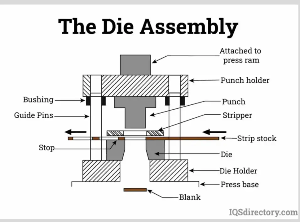
Imagine a coiled strip of metal entering a stamping press and emerging seconds later as a precisely formed component. That's exactly what happens during progressive die stamping. The magic begins when skilled toolmakers create a specialized die set containing all the tools needed for the entire production sequence.
Here's how the transformation unfolds:
- A coiled metal strip feeds automatically into the progressive die
- The stamping press opens, allowing the strip to advance incrementally
- When the press closes, multiple stations simultaneously perform their designated operations
- Each press stroke moves the strip forward by a precise, predetermined distance
- The finished part is eventually cut free from the carrier strip
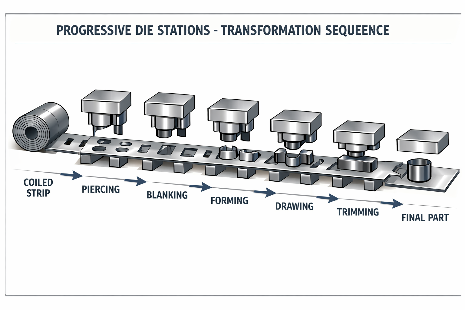
This elegant system means that while one section of the strip undergoes initial piercing, another section further along might be bent, and yet another receives its final forming—all in the same press stroke. The efficiency gains are substantial, enabling manufacturers to produce sheet metal pressings at rates that would be impossible with traditional methods.
The Station-by-Station Forming Principle
What makes sheet metal stamping dies in progressive systems so effective is their station-by-station approach. Each workstation within the die performs one specific task, progressively building upon the work of previous stations. Think of it like an assembly line compressed into a single tool.
As the metal strip advances through the die, it undergoes various operations including:
- Piercing: Creating holes and openings
- Bending: Forming angles and flanges
- Coining: Compressing material for precise dimensions
- Embossing: Adding raised or recessed features
- Cutting: Separating the finished part from the strip
The part remains attached to the carrier strip throughout this journey, ensuring precise positioning at each station. This continuous connection eliminates the need for manual handling between operations and maintains consistent alignment—a critical factor in achieving the tight tolerances that progressive stamping is known for.
Throughout this guide, you'll discover the engineering principles behind strip layout design, essential die components, material selection criteria, and practical troubleshooting techniques. Whether you're evaluating this technology for a new project or looking to optimize existing operations, understanding these fundamentals will help you make informed decisions about your manufacturing processes.
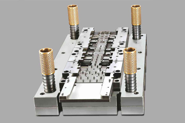
Essential Die Components and Their Functions
What actually happens inside that precision tool that transforms flat metal into complex finished parts? Understanding the anatomy of progressive dies is essential for anyone involved in stamping operations—from engineers designing new tooling to maintenance professionals keeping production running smoothly.
A prog die may appear straightforward from the outside, but inside lies a sophisticated assembly where every component serves a specific engineering purpose. When these stamping die components work in harmony, the result is consistent part quality at remarkable production speeds. When even one element fails or wears prematurely, the entire operation suffers.
Let's examine the critical components that make metal stamping dies such effective production tools:
- Die Block: The central foundation that all other components attach to, forming the die into a single working piece
- Punches: Male components that perform piercing, blanking, and forming operations
- Die Buttons: Precision-ground bushings with profiles matching punch geometry plus required clearance
- Stripper Plate: Holds material down and removes it from punches during retraction
- Pilots: Position the strip accurately for each operation
- Stock Guides: Ensure consistent material positioning throughout the die
- Backing Plates: Hardened plates behind punches providing structural support
- Guide Pins and Bushings: Maintain precise alignment between upper and lower die halves
Punches and Die Blocks Explained
Think of punches as the workhorses of any stamp die—they're the male components that directly contact and shape the material. In a die stamping machine, punches must withstand enormous repeated stresses while maintaining their precise geometry over millions of cycles.
Several punch types perform distinct functions within stamping dies:
- Pierce Punch: Collaborates with the pierce die to remove material from blanked areas, creating holes and openings
- Blank Punch: Works with the blank die to produce the overall part shape
- Forming Punch: Shapes material through bending, drawing, or embossing operations
The die block serves as the female counterpart in cutting operations. According to industry specifications, die buttons are precision-ground bushings with holes matching punch profiles plus a calculated clearance—typically measured in thousandths of an inch. This clearance is critical: too tight causes excessive wear and galling, while too loose produces burrs and dimensional variation.
Behind every punch sits a backing plate—a hardened component that prevents the punch from driving into the softer punch holder under repeated impact. This seemingly simple element significantly extends punch life by distributing forces across a larger area.
How Pilots and Stock Guides Ensure Precision
Here's where the engineering gets particularly interesting. Pilots are among the most important progressive die components because they determine whether every subsequent operation lands exactly where it should. Their function? Positioning the stock strip with precision for each die operation.
The piloting process works through a clever mechanical interaction. As the press descends, the pilot's bullet-shaped nose enters a previously pierced opening in the strip. The tapered profile then cams or pushes the strip opening into perfect alignment. This registration must occur before any cutting or forming punches contact the material—which is why pilots are always longer than working punches in the same die.
Pilot fit tolerances depend on part requirements. For precision work, pilots fit openings with clearances as tight as 0.001 to 0.002 inches per side. This close relationship minimizes lateral movement during registration while preventing excessive friction that accelerates wear. Larger, less critical parts may use greater clearances to accommodate minor construction variations.
Stock guides—also called back gauges or finger stops—complement pilot action by ensuring material enters the die in a consistent position with each stroke. These components control the strip's lateral position and prevent misfeeding that would cascade into registration errors throughout subsequent stations.
The interplay between these components reveals the engineering elegance of progressive dies. The stripper plate holds material firmly against the die surface during forming while simultaneously stripping it from punches during retraction. Guide pins and bushings—precision-ground components on opposing die shoes—ensure the upper and lower halves meet with perfect alignment every time the press cycles.
Understanding how these stamping die components interact helps explain why progressive dies require such careful design and maintenance. A few micrometers of wear in one component can trigger a cascade of quality issues, from dimensional variation to premature failure of adjacent parts. This reality makes component selection and preventive maintenance strategies essential topics—which brings us to how strip layout and station sequencing decisions influence overall die performance.
Strip Layout Design and Station Sequencing Logic
Now that you understand the components working inside a progressive stamping die, here's a critical question: how do engineers decide where each operation happens and in what order? The answer lies in strip layout design—arguably the most intellectually challenging aspect of progressive die engineering.
Think of strip layout as the master blueprint that orchestrates every action within the die. According to industry research, a well-designed layout directly impacts material cost, production speed, part quality, and overall operational efficiency. Get this wrong, and you'll face excessive scrap, inconsistent parts, premature tool wear, and costly production stoppages. Get it right, and you've created a robust process capable of running millions of cycles with minimal intervention.
Strip Layout Engineering Principles
What separates an optimized progressive die design from a merely functional one? It starts with understanding the fundamental calculations and constraints that govern every layout decision.
The primary objectives of effective strip layout include:
- Maximizing material utilization: Target efficiency rates above 75% wherever possible
- Maintaining strip integrity: Ensure the carrier can transport parts through all stations without distortion
- Achieving dimensional accuracy: Position operations to minimize cumulative error
- Optimizing station count: Reduce tooling cost by minimizing the number of required stations
Several critical calculations drive these objectives. The bridge—that small section of material left between parts and between parts and strip edges—must be precisely sized. A common formula determines minimum bridge thickness (B) based on material thickness (t): B = 1.25t to 1.5t. For example, with 1.5mm thick material, you'd design bridges between 1.875mm and 2.25mm. Too thin, and the scrap twists and jams the die. Too thick, and you're wasting expensive raw material.
Strip width (W) follows a straightforward relationship: W = Part Width + 2B. The progression or pitch (C)—the distance the strip advances with each press stroke—typically equals C = Part Length + B. These seemingly simple formulas become complex when applied to parts with irregular geometries or multiple orientations.
Carrier Strip Design Considerations
The carrier strip is the skeletal framework transporting your part from station to station. Its design fundamentally affects whether your stamping die design succeeds or fails. According to design guidelines, carrier width should be at least 2 times the material thickness—larger dies may require even wider carriers to facilitate smooth strip progression.
Two primary carrier types address different production scenarios:
- Solid Carrier: Used when the strip must remain flat throughout processing—ideal for basic cutting and simple bending operations offering maximum stability
- Stretch Web Carrier: Engineered with strategic cuts or loops allowing flexibility and deformation—essential for deep drawing or complex forming where material must flow from the carrier into the part
Practical carrier design tips that experienced toolmakers follow include:
- If using multiple carriers, design them with consistent lengths to prevent strip twisting
- Make carriers long enough to accommodate any stretch or bend during press operations
- Design loops with the largest practical radius while maintaining necessary clearances
- Attach carriers at points allowing easy removal with manageable burr formation
- Use stiffening beads or lance-form edges when fabricating large parts from thin materials
Pilot Hole Positioning Strategy
Where you place pilot holes—and when you create them—directly determines the accuracy of every subsequent operation. The first station in virtually every progressive stamping dies layout performs pilot hole piercing. Why? Because every following operation depends on these reference points for precise positioning.
Strategic pilot positioning follows these engineering principles:
- Punch both pilot holes simultaneously when two sets are required—this ensures better accuracy than sequential piercing
- Space pilots on the carrier to account for any strip elongation during forming operations
- When part holes are large enough, they can serve as pilots—but recognize this may cause slight elongation affecting tight tolerances
- Position pilots to provide maximum registration accuracy at critical forming stations
Station Sequencing for Optimal Results
Sounds complex? It is—but the sequencing logic follows established manufacturability rules that have evolved over decades of progressive metal stamping experience. Research on optimization shows that proper sequencing minimizes die stations, reducing tooling costs while satisfying all precedence and adjacency constraints.
Here's the typical station sequence logic that governs most progressive punch operations:
- Pilot Hole Piercing: Always first—these holes establish registration for all subsequent operations
- Piercing Operations: Create all holes and openings before any forming occurs—piercing through flat material produces cleaner edges than piercing through formed sections
- Notching and Lancing: Remove material to create clearances needed for upcoming bends or draws
- Embossing (if required): When embosses exist, they're often stamped early to prevent deformation of other features
- Forming and Bending: Shape the part progressively—smaller forms before larger ones to maintain strip stability
- Coining and Sizing: Final precision operations that refine critical dimensions
- Cutoff or Blanking: Separate the finished part from the carrier strip
Why this specific order? The reasoning is both mechanical and practical:
- Piercing before forming ensures holes maintain their intended geometry—forming after piercing would distort hole shapes
- Notching before bending creates necessary material clearances and prevents tearing during forming
- Smaller forms before larger forms maintains strip flatness longer, improving registration accuracy at subsequent stations
- Cutoff last keeps the part attached to the carrier for maximum positioning control throughout all operations
Adjacency and Precedence Constraints
Beyond simple sequencing, engineers must consider which operations can share a station and which must remain separated. Two critical constraint types govern these decisions:
- Precedence constraints: The mandatory order of operations based on part features—piercing must precede forming of adjacent areas
- Adjacency constraints: Prohibitions against performing specific operations at the same station—features too close together require separate stations to prevent die weakening
When holes or scraps to be pierced are close to each other, they should be shifted to separate die stations. This prevents the "weak die problem" where insufficient material between punch locations causes premature tool failure. Empty stations can actually improve die performance by distributing forces more evenly and allowing space for future operation additions.
Modern CAD and CAE software has transformed how engineers approach these complex decisions. Simulation allows designers to validate entire strip layouts virtually—predicting how metal will flow, stretch, and thin before any steel is cut. This "predict-and-optimize" approach replaces costly trial-and-error methods, significantly reducing development time and improving first-pass success rates.
Understanding these strip layout principles sets the foundation for evaluating whether your part designs are truly optimized for progressive die production—which brings us to practical manufacturability guidelines that separate excellent designs from problematic ones.
Design for Manufacturability Guidelines
You've seen how strip layouts and station sequencing determine progressive die efficiency. But here's the reality that many engineers learn the hard way: even the most elegant tooling design can't compensate for a poorly conceived part. The features you specify—bend radii, hole locations, material thickness, tolerances—ultimately determine whether your progressive die stampings will be produced efficiently or become a constant source of headaches.
Design for manufacturability (DFM) isn't about limiting creativity. It's about understanding which features excel in progressive die production and which ones drive up costs, increase scrap rates, or cause outright failures. Let's explore the practical guidelines that separate precision die stamping successes from expensive lessons.
Part Features That Excel in Progressive Dies
What makes a part ideally suited for progressive die production? According to industry guidelines, the best candidates share common characteristics that align with the process's inherent strengths.
Material Thickness Sweet Spot
Progressive stamping operations work most efficiently with material thicknesses between 0.127 mm (0.005 in) and 6.35 mm (0.25 in). Within this range, you'll achieve optimal balance between formability and structural integrity. Thinner materials require more careful handling to prevent distortion, while thicker stock demands more robust tooling and higher press forces—both increasing costs.
Ideal Feature Characteristics
Parts that run smoothly through progressive dies typically include:
- Generous bend radii: Inside bend radius should equal or exceed material thickness—larger radii reduce springback and cracking risk
- Adequate hole-to-edge distance: Maintain minimum distance of 1.5 times material thickness from holes to edges or bends
- Consistent material grain orientation: Bends perpendicular to grain direction are stronger and less prone to cracking
- Simple, repeatable geometries: Features that can be formed in single operations reduce station count and tooling complexity
- Symmetrical designs: Balanced parts reduce uneven forces that can cause strip feeding issues
An excellent example of stamping design optimization involves positioning holes away from formed areas. When holes must exist near bends, piercing them after forming prevents distortion—but this requires additional stations. Smart designers relocate holes when possible, reducing tooling complexity.
Avoiding Costly Design Mistakes
Sounds straightforward so far? Here's where things get interesting. Certain design choices that seem minor on CAD models create significant manufacturing challenges. Understanding these pitfalls before finalizing your design saves substantial time and money.
The following table compares ideal features with challenging ones, along with practical recommendations:
| Feature Type | Ideal Design | Problematic Design | Recommendation |
|---|---|---|---|
| Bend Radius | ≥ Material thickness | Sharp corners (< 0.5t) | Specify minimum 1t radius; use 2t for high-strength materials |
| Hole Diameter | ≥ Material thickness | < 0.8 × material thickness | Increase hole size or consider secondary drilling operation |
| Hole-to-Edge Distance | ≥ 1.5 × material thickness | < 1 × material thickness | Relocate holes or add material to edge |
| Hole-to-Bend Distance | ≥ 2 × material thickness + bend radius | Holes adjacent to bend lines | Move holes away from bend areas or pierce after forming |
| Part Geometry | Uniform wall thickness, simple forms | Extreme aspect ratios, undercuts | Simplify geometry or consider alternative processes |
| Tolerance Specification | ±0.127 mm (±0.005 in) standard | ±0.025 mm (±0.001 in) throughout | Apply tight tolerances only to critical features |
Tolerance Capabilities and Realistic Expectations
Understanding achievable tolerances prevents both over-specification (which drives up costs) and under-specification (which causes assembly problems). According to precision die and stamping standards, standard blanking and forming operations typically achieve tolerances of ±0.127 mm (±0.005 in). With specialized equipment like fineblanking and tight process control, critical features can be held to ±0.025 mm (±0.001 in).
However, several factors affect achievable accuracy:
- Material springback: Elastic recovery after forming varies by material type and thickness
- Die wear: Progressive degradation affects dimensions over production runs
- Temperature variation: Thermal expansion impacts both tooling and material
- Cumulative positioning error: Registration variations compound through multiple stations
When tighter tolerances are absolutely required—say ±0.0127 mm (±0.0005 in)—secondary operations become necessary. Precision stamp applications may incorporate CNC machining, grinding, or specialized finishing after primary stamping operations.
Geometry Considerations That Reduce Problems
Complex progressive die stampings often require intricate tooling that increases production costs and extends lead times. According to metal stamping die design experts, simplifying part geometry wherever possible reduces die wear and improves production efficiency.
Practical strategies include:
- Eliminating unnecessary details that don't affect part function
- Combining features where possible to reduce station count
- Standardizing dimensions across product families for tooling commonality
- Avoiding features requiring opposite-direction forming within the same station
- Designing with draft angles that allow smooth part ejection from dies
One often-overlooked consideration: grain direction alignment. Bends made perpendicular to the material grain are significantly stronger and far less susceptible to cracking than bends parallel to the grain. Critical bends must be correctly aligned in the strip layout, which sometimes means orienting parts at angles that increase material usage but dramatically improve part quality.
Prototyping Before Full Production
Here's practical advice that saves significant expense: validate designs through prototyping before committing to progressive die tooling. Creating functional samples using alternative methods—3D printing, CNC machining, or single-stage stamping—allows testing of form, fit, and function under real conditions. This approach identifies potential issues early when design changes are inexpensive rather than after tooling is complete.
With these manufacturability principles in mind, you're equipped to evaluate whether your designs are truly optimized for progressive die production. But how does this process compare to other stamping methods? Understanding when progressive dies outperform alternatives—and when they don't—requires examining the full spectrum of available technologies.
Progressive Die vs Transfer Die vs Compound Die Stamping
You've now mastered the fundamentals of progressive die design and manufacturability. But here's the question every manufacturing engineer eventually faces: is progressive stamping actually the right choice for your specific application? The answer depends on understanding how this process compares to alternatives—and when each method truly excels.
Choosing between different types of stamping dies isn't simply about preference. It's about matching process capabilities to your specific part geometry, production volume, quality requirements, and budget constraints. According to industry comparisons, each stamping method has unique strengths suited to different manufacturing scenarios.
Let's break down the four primary stamping approaches and examine exactly when each one makes sense.
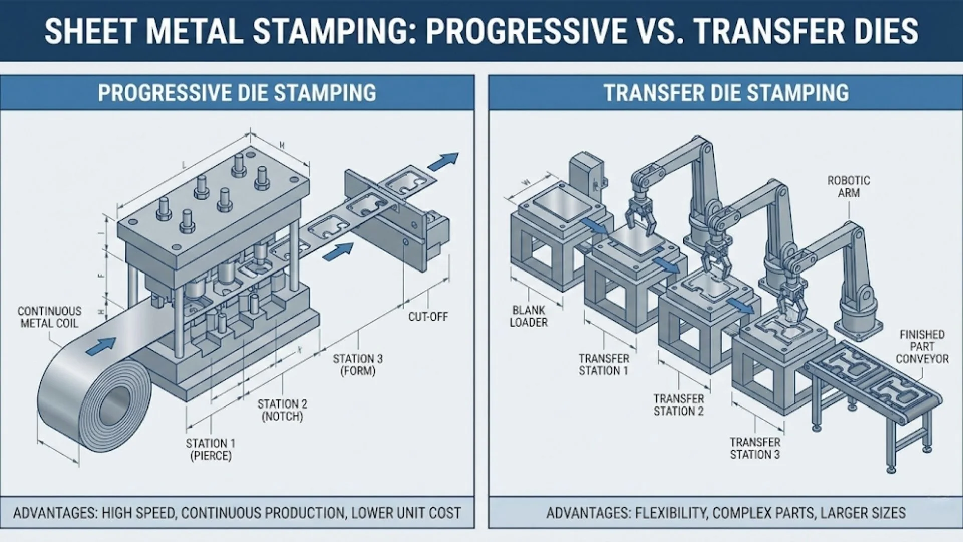
Progressive vs Transfer Die Operations
Progressive Die Stamping
As you've learned throughout this guide, progressive stamping moves a continuous metal strip through sequential stations within a single die. The part remains attached to the carrier strip until the final cutoff operation. A progressive stamping press cycles rapidly—often 100+ strokes per minute—making this method unmatched for high-volume production of small to medium-sized components.
Key characteristics include:
- Continuous strip feeding enables extremely fast cycle times
- Parts stay connected to carrier strip, ensuring precise positioning throughout operations
- Ideal for complex parts requiring multiple operations (bending, piercing, forming)
- High initial tooling investment offset by low per-part costs at volume
- Best suited for parts that fit within strip width constraints
Transfer Die Stamping
Transfer die stamping takes a fundamentally different approach. According to industry experts, this process either begins with a pre-cut blank or separates the part from the strip early in the operation. Once detached, mechanical transfer systems move the individual part between stations.
Think of transfer stamping as an assembly line where each station contributes something specific to the final product. This flexibility comes with trade-offs:
- Parts move independently, allowing more complex shapes and deeper draws
- Larger part sizes are feasible—not constrained by strip width
- Multiple orientations possible during forming operations
- Slower cycle times compared to progressive stamping
- Higher operational costs due to transfer mechanism complexity
When would you choose a transfer die over progressive stamping? Transfer press stamping excels with larger components that require substantial material deformation—automotive body panels, structural brackets, and deep-drawn housings that simply won't work within progressive die constraints.
Compound Die Stamping
Compound die stamping represents the simplest approach in this comparison. Multiple cutting and forming operations happen simultaneously in a single press stroke. Unlike progressive dies with their sequential stations, compound dies perform everything at once.
This simplicity offers specific advantages:
- Lower tooling costs than progressive or transfer dies
- Excellent for flat parts requiring precise cut edges
- High accuracy for simple geometries
- Efficient material utilization with minimal scrap
However, compound die stamping has clear limitations. According to tooling specialists, this method is restricted to simpler, flat parts. Complex 3D geometries or parts requiring multiple forming operations aren't candidates for compound dies.
Single-Stage Operations
Single-stage stamping—performing one operation per press stroke—remains viable for specific situations:
- Very low production volumes where tooling investment isn't justified
- Prototype and development work before committing to production tooling
- Extremely large parts exceeding transfer die capabilities
- Simple operations like blanking or basic bending
The trade-off? Much higher per-part costs and longer production times due to multiple handling and setup requirements between operations.
Choosing the Right Stamping Method
The following table provides a comprehensive comparison across the critical decision criteria for die and stamping method selection:
| Criteria | Progressive Die | Transfer Die | Compound Die | Single-Stage |
|---|---|---|---|---|
| Production Volume | High to very high (100,000+ parts) | Medium to high (10,000-500,000 parts) | Low to medium (1,000-100,000 parts) | Low (prototypes to 5,000 parts) |
| Part Complexity | Simple to complex with multiple features | Highly complex, deep draws, large parts | Simple, flat parts only | Simple single operations |
| Part Size Range | Small to medium (limited by strip width) | Medium to large (fewer size constraints) | Small to medium flat parts | Any size |
| Tooling Cost | High initial investment | High (complex transfer mechanisms) | Moderate | Low per tool, high cumulative |
| Per-Part Cost | Very low at volume | Low to moderate | Low for simple parts | High |
| Cycle Time | Very fast (100+ strokes/min possible) | Moderate (transfer time required) | Fast (single stroke completion) | Slow (multiple setups) |
| Setup Time | Moderate to long | Long (complex alignment required) | Short to moderate | Short per operation |
| Tolerance Capability | ±0.127 mm standard, tighter possible | ±0.127 mm standard | Excellent for cut features | Varies by operation |
| Best Applications | Electrical connectors, brackets, clips, terminals, automotive components | Body panels, structural components, large housings, deep-drawn parts | Washers, simple brackets, flat precision parts | Prototypes, low-volume specialty parts |
Decision Framework: Which Method Fits Your Needs?
Selecting the optimal stamping method involves evaluating several interconnected factors. Here's a practical decision framework:
Choose Progressive Die Stamping when:
- Annual volumes exceed 100,000 parts
- Parts require multiple operations (piercing, bending, forming)
- Part dimensions fit within practical strip width limits
- Consistent, repeatable quality is critical
- Per-part cost reduction is a primary goal
Choose Transfer Die Stamping when:
- Parts are too large for progressive die strip constraints
- Deep draws or complex 3D geometries are required
- Part orientation must change during forming operations
- Medium to high volumes justify transfer mechanism investment
Choose Compound Die Stamping when:
- Parts are flat or require minimal forming
- Edge quality and dimensional accuracy are paramount
- Lower tooling investment is preferred
- Production volumes are moderate
Choose Single-Stage Operations when:
- Volumes are too low to justify dedicated tooling
- Parts are prototypes or developmental samples
- Extreme part sizes exceed other method capabilities
- Flexibility to modify designs is required
Understanding these trade-offs helps you make informed decisions that balance quality requirements, production economics, and delivery timelines. But regardless of which stamping method you select, material choice fundamentally affects both process performance and final part quality—a topic that deserves careful examination.
Material Selection for Progressive Die Operations
You've determined that progressive die stamping fits your production requirements. Now comes a decision that will influence everything from die longevity to part performance: which material should you run? Selecting the right metal isn't just about meeting part specifications—it directly affects how your steel stamping tools perform, how much progressive scrap metal you generate, and ultimately, your production economics.
According to industry experts, manufacturers can use brass, aluminum, copper, and various types of steel in progressive stamping operations. However, each material brings distinct characteristics that affect formability, die wear, and finished part quality. Understanding these trade-offs helps you balance performance requirements against production realities.
Several key factors should guide your material selection:
- Formability: How easily the material bends, draws, and shapes without cracking
- Tensile strength: Resistance to pulling forces during and after forming
- Corrosion resistance: Environmental durability for the intended application
- Cost and availability: Budget constraints and supply chain considerations
- Machinability: How smoothly the material processes through your sheet metal die
Steel Grades for Progressive Stamping
Steel remains the workhorse material for steel stamping dies operations, offering an exceptional balance of strength, formability, and cost-effectiveness. Different grades serve different purposes—understanding these distinctions prevents costly mismatches between material and application.
Carbon Steel
Carbon steel combines iron with carbon to create a highly durable alloy offering superior strength and design flexibility. According to material specifications, this material is cost-effective and compatible with many metal-forming processes. The trade-off? Carbon steel requires protective coatings—zinc, chrome, or nickel—to enhance corrosion resistance for applications exposed to moisture or chemicals.
Common applications include automotive stamping dies components, structural brackets, and general-purpose formed parts where strength matters more than inherent corrosion protection.
Stainless Steel
When corrosion resistance is non-negotiable, stainless steel delivers. This material offers exceptional mechanical properties including magnetism resistance, an attractive smooth finish, and surfaces that are easy to maintain. Stainless steel proves ideal for food handling equipment and medical device applications where hygiene and durability are paramount.
However, stainless steel presents stamping challenges. Higher strength requires greater press forces, and work hardening during forming can cause premature die wear. Steel stamping tools running stainless grades need more frequent maintenance and sometimes specialized coatings to maintain productivity.
Non-Ferrous Material Considerations
Non-ferrous metals—those without iron—offer properties that steel simply cannot match. Electrical conductivity, lightweight construction, and decorative appeal make these materials essential for specific applications.
Aluminum
This silvery-white, soft metal offers a high strength-to-weight ratio, excellent formability, resilience, and an attractive finish. Aluminum excels in lightweight stamped components and thermal or electrical conductors. Aerospace, automotive, and electronics industries rely heavily on aluminum progressive stampings.
The challenge? Aluminum's softness can cause galling—material transfer to die surfaces—requiring special lubricants and sometimes die coatings to maintain quality.
Copper and Copper Alloys
Copper progressive stamping dominates electrical connector and component manufacturing. Why? Copper offers unmatched electrical and thermal conductivity combined with corrosion resistance and ductility. The soft, malleable nature makes it ideal for complex forming operations.
Beryllium copper—a specialized alloy—provides high-stress tolerance for bearings, aircraft engine components, and springs requiring resistance to stress relaxation. This material offers the conductivity benefits of copper with significantly enhanced mechanical properties.
Brass
Brass contains varying amounts of zinc and copper, providing adjustable proportions of malleability and hardness. This versatility makes it suitable for bearings, locks, gears, and valves. Beyond functional applications, brass offers visual appeal for decorative hardware and ornamental items.
The following table compares common materials used in progressive stamping operations:
| Material | Formability Rating | Typical Applications | Key Considerations |
|---|---|---|---|
| Carbon Steel | Good | Structural brackets, automotive components, general-purpose parts | Requires coating for corrosion protection; excellent cost-effectiveness |
| Stainless Steel | Moderate | Food handling equipment, medical devices, corrosive environments | Higher press forces required; work hardens during forming; increased die wear |
| Aluminum | Excellent | Lightweight components, thermal conductors, aerospace parts | Prone to galling; requires specialized lubricants; springback considerations |
| Copper | Excellent | Electrical connectors, thermal components, food processing equipment | Soft and malleable; easy to form; excellent conductivity |
| Beryllium Copper | Good | Springs, bearings, aircraft engine components | High stress tolerance; corrosion resistant; specialized handling required |
| Brass | Good to Excellent | Bearings, locks, gears, valves, decorative hardware | Adjustable hardness via zinc content; thermal and electrical conductivity |
Material Properties Affecting Die Performance
Beyond selecting the right material for your part's application, consider how material properties affect your progressive die operation itself. According to forming specialists, several characteristics directly impact production efficiency:
- Bend rating: Measures formability based on ability to bend without breaking—higher ratings mean easier processing
- Work hardening tendency: Some materials strengthen during deformation, requiring adjusted forming sequences
- Surface finish requirements: Material choice affects available finishing options like passivation, anodizing, or plating
- Springback characteristics: Elastic recovery after forming varies significantly between materials
Matching material properties to your specific forming requirements minimizes progressive scrap metal generation and extends die life. This careful alignment between material and process sets the stage for consistent, trouble-free production—though even optimized operations occasionally encounter challenges that require systematic troubleshooting approaches.
Troubleshooting Common Progressive Die Problems
Even the most carefully designed progressive die metal stamping operations encounter problems. The difference between production teams that struggle and those that thrive? A systematic approach to diagnosing issues and implementing effective solutions. When your die stamping operation starts producing rejects, knowing exactly where to look—and what corrective actions actually work—saves hours of frustration and prevents costly scrap.
According to industry research, most stamping die problems fall into predictable categories with well-established solutions. Let's examine the issues you're most likely to encounter and the proven fixes that get production back on track.
Diagnosing Strip Feed Issues
When the metal strip doesn't advance properly, everything downstream suffers. Material jammed in your metal stamping die creates cascading failures—misregistered holes, incomplete forms, and damaged tooling. What causes these feeding nightmares?
Common strip feeding problems include:
- Feeder misadjustment: Incorrect feed distance, pressure settings, or release timing
- Material quality issues: Curved strips, excessive width variation, or large burrs on incoming coil
- Sickle bend: Strip curves laterally due to uneven burrs or stamping forces
- Strip warping: Thin materials warp during feeding, especially between feeder and die
- Guide plate interference: Improper stripping function causes material to lift onto the strip
Solutions vary by root cause. Re-adjusting feeder settings often resolves simple timing issues. When material quality is the culprit, working with suppliers to control incoming specifications—or adding trimming devices to the die—addresses the source rather than symptoms. For thin materials prone to warping, adding upper and lower pressing mechanisms between feeder and die provides the stability needed for consistent advancement.
Solving Dimensional Accuracy Problems
When die stamped parts start drifting out of tolerance, production quality suffers immediately. Dimensional variation stems from multiple sources, making systematic diagnosis essential.
The following table organizes common progressive die problems with their root causes and corrective actions:
| Problem | Root Causes | Corrective Actions |
|---|---|---|
| Burr Formation | Knife edge wear; excessive clearance; edge collapse; misaligned punches and dies | Grind cutting edges; control machining precision; adjust punch-die clearance; replace worn guide components |
| Dimensional Variation | Worn pilot pins with insufficient diameter; guide wear; improper feeder adjustment; stripping insert wear | Replace pilot pins; replace guide posts and bushings; re-adjust feeder settings; grind or replace stripping inserts |
| Chip/Slug Sticking | Excessive clearance; oil viscosity issues; magnetized die; worn punch compressing scrap | Control clearance precision; adjust oil amount or change lubricant type; demagnetize after sharpening; re-grind punch end face |
| Material Blockage | Undersized slug hole; oversized hole causing rollback; worn edges creating burrs; rough die surfaces | Modify slug escape holes; re-grind cutting edges; polish die surfaces; reduce surface roughness |
| Punch Breakage | Chip blocking; insufficient punch strength; clearance too small; uneven clearance causing interference | Solve chip ejection issues; increase punch cross-section; adjust clearances; check forming part accuracy |
| Bending Deformation | Worn guide pins; bending guide wear; material slip without preload; excessive shim stacking | Replace guide pins; add lead-in and preload functions; use solid steel shim plates; adjust bending inserts |
Die Processing Maintenance That Extends Tool Life
Prevention beats correction every time. Regular maintenance practices dramatically reduce troubleshooting frequency and extend your metal stamping die investment:
- Scheduled edge inspection: Check cutting edges before wear creates burrs—proactive grinding extends intervals between major repairs
- Demagnetization after sharpening: Particularly critical for ferrous materials; magnetized components attract chips that cause blocking and wear
- Lubrication optimization: Match oil viscosity to material and speed; excessive lubricant causes sticking while insufficient lubricant accelerates wear
- Clearance verification: Periodically measure punch-die clearances; worn components create progressive quality degradation
- Documentation discipline: Mark components during disassembly; record shim quantities and positions; maintain written logs for inquiry
One often-overlooked maintenance consideration: foolproofing your die assembly. According to production specialists, molds without foolproof features lead to reverse direction assembly and station misalignment. Modifying dies to include anti-error features—and implementing confirmation checks after assembly—prevents costly mistakes that damage tooling and produce scrap.
Understanding these troubleshooting fundamentals prepares you to maintain consistent quality. But beyond day-to-day operations, making sound progressive die investments requires clear economic analysis—evaluating when tooling costs justify themselves against production volumes and alternative manufacturing methods.
Cost Analysis and ROI Considerations
You've mastered the technical fundamentals—now comes the question that ultimately drives manufacturing decisions: does progressive die investment make financial sense for your production needs? Understanding the metal stamping manufacturing process economics separates informed decision-makers from those who either overspend on unnecessary tooling or miss cost-saving opportunities.
According to industry analysis, the economic model of progressive stamping follows a classic trade-off: you accept a high initial cost to secure an extremely low price per piece across long production runs. This front-loaded investment structure means that break-even calculations—not just technical capability—determine whether progressive tooling is your optimal path.
Calculating Progressive Die ROI
What factors actually drive progressive die tooling costs? Understanding these variables helps you evaluate quotes accurately and identify opportunities for cost optimization.
Key cost factors to evaluate when considering stamping tooling investment include:
- Part complexity: Number of stations required directly impacts die size and construction cost
- Material type and thickness: Harder materials require premium die steels and specialized coatings
- Tolerance requirements: Tighter specifications demand precision machining and additional tryout time
- Production volume expectations: Higher lifetime volumes justify enhanced die materials for longevity
- Secondary operation elimination: Progressive die components that combine operations reduce total manufacturing cost
- Die complexity features: Cams, lifters, and in-die tapping add cost but may eliminate downstream operations
- Engineering and design time: Complex strip layouts require more upfront analysis
According to manufacturing research, progressive dies fundamentally alter cost composition. While upfront design and build costs represent substantial capital investment, once production begins, unit variable costs drop to bare minimums. Labor costs plummet since operators manage the feeder and press rather than handling individual parts. Material utilization improves through optimized strip layouts. Quality costs decrease as die-controlled precision replaces operator-dependent accuracy.
The ROI calculation framework follows this logic:
- Total Tooling Investment: Die design + die construction + tryout + modifications
- Per-Part Cost Savings: (Alternative method cost per part) - (Progressive die cost per part)
- Break-Even Volume: Total Tooling Investment ÷ Per-Part Cost Savings
- Payback Period: Break-Even Volume ÷ Annual Production Volume
Volume Thresholds for Tooling Investment
When does long run metal stamping investment truly make financial sense? The answer depends on comparing progressive die economics against alternative manufacturing methods.
According to economic analysis, if your product meets three criteria—annual volume above 50,000 parts, stable design, and relatively complex geometry—investing in a progressive die is no longer a choice but a strategic decision with highly predictable returns.
Consider this quantitative comparison between manufacturing methods:
| Criteria | Progressive Die | Transfer Die | Single-Stage Operations |
|---|---|---|---|
| Initial Tooling Cost | $50,000 - $500,000+ | $75,000 - $750,000+ | $5,000 - $25,000 per operation |
| Break-Even Volume | 50,000 - 100,000 parts typical | 25,000 - 75,000 parts typical | Immediate (no tooling amortization) |
| Per-Part Cost at Volume | Lowest | Low to moderate | Highest |
| Best Economic Fit | 100,000+ annual volume | 10,000 - 500,000 annual volume | Under 5,000 parts |
Beyond Initial Investment: Lifecycle Cost Considerations
Progressive die manufacturers emphasize that true ROI extends beyond the initial purchase. According to lifecycle analysis, the actual return on progressive die investment depends on productive die life—not just upfront cost.
Long-term cost factors that sophisticated buyers evaluate include:
- Maintenance frequency: Regular sharpening, component replacement, and preventive care
- Downtime costs: Production losses during repairs and unplanned stoppages
- Die life expectancy: Premium die materials cost more initially but last significantly longer
- Replacement part availability: Quick access to precision replacement components minimizes downtime
- Design stability: Engineering changes requiring die modifications add cumulative cost
The complete lifecycle cost formula reveals important truths:
Lifecycle Cost = Initial Investment + (Σ Maintenance Costs + Σ Downtime Losses + Σ Scrap Costs)
A low-cost but poorly designed, hard-to-maintain die can become a bottomless pit of hidden expenses, making its total cost several times higher than that of an initially expensive but well-engineered, easily serviceable tool. Progressive die manufacturers who build maintenance accessibility into their designs deliver better long-term value even when initial quotes appear higher.
Decision Framework for Tooling Investment
Before committing capital to progressive die tooling, systematically evaluate these economic decision criteria:
- Is annual production volume sufficient to amortize tooling cost within acceptable payback period?
- Is the part design stable, or are engineering changes likely during production life?
- What alternative manufacturing methods exist, and what are their comparative per-part costs?
- Does part complexity require multiple operations that progressive tooling can consolidate?
- What is the expected product lifecycle, and will volumes sustain long enough for full payback?
- Are secondary operations currently required that could be eliminated with progressive die integration?
This economic framework transforms tooling decisions from gut instinct into data-driven analysis. With clear understanding of both cost structures and break-even thresholds, you're equipped to make investment decisions that deliver genuine competitive advantage—particularly in demanding applications like automotive manufacturing where volume, quality, and cost requirements converge.
Automotive Applications and OEM Requirements
Now that you understand the economic framework for tooling investment, where does progressive die stamping deliver its most compelling value? The automotive industry represents the ultimate proving ground—where demanding quality standards, massive production volumes, and relentless cost pressure converge. This sector accounts for a substantial portion of global progressive die & stamping activity, and for good reason.
According to automotive manufacturing research, stamped components form the backbone of vehicle production, providing the essential link between material science, design requirements, and vehicle performance. From structural frames to intricate interior fittings, these parts define not only the geometry but also the strength, safety, and durability of modern automobiles.
What makes automotive stamping die applications so demanding? Consider this: a single vehicle requires thousands of stamped components, many of which must be lightweight yet strong—characteristics that progressive stamping processes are uniquely capable of producing at scale.
Typical automotive applications for progressive stamped automotive parts include:
- Electric and Hybrid Vehicles: High-precision motor laminations, connectors, and bus bars essential for EV powertrains
- Structural Components: Durable, lightweight parts for automotive frames and bodies including cross members and suspension supports
- Body Panels and Brackets: Door reinforcements, fender supports, and mounting brackets requiring dimensional accuracy
- Powertrain Components: Transmission housings, clutch covers, and engine-related brackets demanding precision alignment
- Interior Systems: Seat structures, pedal assemblies, dashboard frames, and reinforcement brackets
- Electrical Connectors: Terminals, contacts, and bus bars for vehicle wiring systems
Meeting Automotive OEM Standards
Here's a critical reality that separates automotive progressive stamping from general manufacturing: OEM quality requirements leave zero margin for error. According to certification specialists, the automotive industry demands specialized quality management systems that go far beyond standard manufacturing practices.
IATF 16949 certification has become the global benchmark for automotive stamping die suppliers. Originally drafted by the International Automotive Task Force, this specialized certification harmonizes quality assessment systems throughout the global automotive industry. The three primary aims include:
- Improving both product quality and consistency along with the manufacturing processes that create them—reducing production costs and ensuring long-term sustainability
- Establishing "supplier of choice" status among leading automotive manufacturers through proven consistency and accountability
- Seamlessly integrating with industry-wide ISO certification standards for comprehensive quality management
What does IATF 16949 mean for oem progressive stamping operations? The certification focuses intensely on defect prevention and production variance minimization—exactly what high-volume automotive components progressive stamping demands. It requires increased attention to customer-specific needs, expectations, and requirements while maintaining rigorous process controls.
Beyond certification, advanced simulation technologies have transformed how automotive stamping partners approach quality assurance. CAE (Computer-Aided Engineering) simulation allows engineers to predict how metal will flow, stretch, and thin before any die steel is cut. This capability proves invaluable for automotive applications where first-pass approval rates directly impact production timelines and costs. Companies like Shaoyi leverage these advanced CAE simulation capabilities combined with IATF 16949 certification to deliver defect-free results—achieving a 93% first-pass approval rate that meets stringent OEM standards.
Quality requirements for automotive stamped components span multiple dimensions:
- Dimensional Accuracy: Even minor deviations cause misalignment, assembly gaps, or noise and vibration issues in finished vehicles
- Surface Quality: Visible body panels demand flawless surfaces free from scratches, dents, or waviness
- Material Integrity: Parts must maintain mechanical strength after forming, verified through tensile tests, hardness measurements, and fatigue resistance assessments
- Forming Defect Prevention: Cracks, wrinkles, or thinning can compromise safety under operational stress
- Corrosion Resistance: Vehicles operate in diverse climates, requiring galvanizing, coating, or painting for long service life
High-Volume Automotive Component Production
When automotive manufacturers need hundreds of thousands—or millions—of identical components, progressive die stamping becomes the only practical choice. According to industry leaders, modern automotive stamping dies support production speeds up to 1,400 strokes per minute, enabling fast and efficient manufacturing that matches assembly line demands.
This high-speed capability isn't just about raw throughput. Automotive production economics demand minimal waste and consistent quality across extended runs. Progressive stamping delivers both through:
- Precision and Accuracy: Delivering consistent results with tight tolerances for high-quality components across millions of cycles
- Durability: Dies built to withstand high production volumes and challenging manufacturing environments
- Versatility: Supporting diverse automotive applications from powertrain components to interior fittings
- In-Die Process Integration: Advanced capabilities including in-die assembly and in-die tapping that eliminate secondary operations
The ability to integrate complex features directly into progressive stamping dies enhances productivity while maintaining precision and repeatability. Tooling that enables components to be assembled within the die streamlines production and reduces handling time. Similarly, in-die threading capabilities eliminate separate tapping operations, improving throughput significantly.
Interestingly, the precision manufacturing principles that drive automotive stamping excellence also apply to other demanding sectors. Medical progressive stamping, for instance, shares similar requirements for dimensional accuracy, material integrity, and defect-free production—demonstrating how automotive-grade capabilities translate across industries.
For manufacturers entering the automotive supply chain, partner selection becomes critical. Rapid prototyping capabilities—some suppliers offer turnaround in as little as 5 days—enable design validation before committing to production tooling. Engineering teams with deep automotive experience understand OEM-specific requirements and can translate those needs into tooling solutions that deliver quality from the first production run.
Whether you're producing components for traditional internal combustion vehicles or the rapidly growing electric vehicle segment, understanding these automotive-specific demands positions you to make informed decisions about progressive die implementation—decisions that ultimately determine your competitiveness in this demanding market.
Implementing Progressive Die Stamping Successfully
You've journeyed through the complete progressive die stamping process—from strip layout engineering to material selection, troubleshooting techniques, and automotive OEM requirements. Now comes the practical question: how do you translate this knowledge into successful implementation for your manufacturing operations?
Whether you're evaluating progressive die and stamping for a new product launch or considering conversion from alternative manufacturing methods, systematic assessment ensures you make decisions that deliver long-term value rather than short-term regrets.
Evaluating Your Production Requirements
Before committing to dies and stamping investment, honest evaluation of your specific circumstances determines whether progressive tooling aligns with your production reality. According to industry specialists, utilizing progressive die stamping for full production runs can be a major source of cost savings—but only when the application fits the process capabilities.
Key questions to answer during your evaluation:
- Volume assessment: Do annual quantities exceed 50,000-100,000 parts to justify tooling investment?
- Design stability: Is your part design finalized, or are engineering changes likely during production?
- Geometry compatibility: Does your part fit within strip width constraints with appropriate bridge dimensions?
- Material suitability: Is your specified material formable through progressive stamping operations?
- Tolerance requirements: Can standard progressive die capabilities meet your dimensional specifications?
- Secondary operation elimination: Will progressive tooling consolidate operations currently performed separately?
Understanding what is dies in manufacturing context helps frame your decision. Progressive dies represent precision engineered tools designed for specific parts—not flexible equipment that adapts to changing requirements. This specialization delivers exceptional per-part economics but demands upfront commitment to stable designs and sufficient volumes.
Next Steps for Implementation
Ready to move forward? The progressive stamping process implementation follows a logical sequence that minimizes risk while accelerating time-to-production.
Phase 1: Design Validation
Before investing in production tooling, validate your part design through prototyping. According to conversion specialists, even if prototypes are fabricated through traditional machining operations, they can still be evaluated for progressive die suitability. This approach identifies potential issues early when design changes remain inexpensive. Manufacturers offering rapid prototyping capabilities—some delivering samples in as little as 5 days—enable quick validation cycles that accelerate your decision-making.
Phase 2: Partner Selection
Choosing the right stamping die manufacturing partner directly impacts your success. According to selection criteria, reliable manufacturers combine engineering expertise, high-precision equipment, and strict quality management to deliver tools that perform under pressure. Evaluate potential partners on:
- Design and engineering capabilities including CAD/CAM software and simulation tools
- Manufacturing precision—top-tier suppliers maintain tolerances within ±0.005 mm
- Quality certifications appropriate to your industry (IATF 16949 for automotive)
- Communication responsiveness and project management transparency
- After-sales support including maintenance, troubleshooting, and reconditioning services
Phase 3: Collaborative Development
The most successful progressive die implementations involve close collaboration between your engineering team and your tooling partner. Share complete part requirements, tolerance priorities, and production volume expectations upfront. Engineering teams with deep stamping experience can often suggest design modifications that reduce tooling complexity while maintaining part function—delivering cost savings before production even begins.
For manufacturers seeking a partner with comprehensive capabilities, Shaoyi's precision stamping die solutions offer engineering support backed by IATF 16949 certification and advanced CAE simulation. Their 93% first-pass approval rate demonstrates the value of experienced engineering collaboration in achieving defect-free results from initial production runs.
Key Takeaways for Progressive Die Success
As you move forward with your progressive die stamping process evaluation, keep these essential principles in mind:
- Match process to volume: Progressive dies excel at 100,000+ annual parts—lower volumes may suit alternative methods
- Design for manufacturability: Optimize part geometry before tooling design begins to minimize stations and cost
- Select materials strategically: Material properties affect die performance, maintenance frequency, and part quality
- Invest in quality tooling: Low-cost dies often deliver higher lifecycle costs through maintenance and downtime
- Plan for maintenance: Establish preventive maintenance schedules before production begins
- Validate before committing: Prototype testing prevents expensive discoveries after tooling is complete
- Partner wisely: Technical expertise and communication quality matter as much as quoted price
The progressive die stamping process has transformed manufacturing across industries by delivering precision, speed, and economy at scale. With the knowledge you've gained throughout this guide—from strip layout engineering to troubleshooting techniques to economic analysis—you're equipped to evaluate whether this powerful technology fits your production needs and to implement it successfully when the answer is yes.
Frequently Asked Questions About Progressive Die Process
1. How does a progressive die work?
A progressive die works by feeding a continuous metal strip through multiple stations within a single die. Each station performs a specific operation—such as piercing, bending, or forming—as the strip advances with each press stroke. The part remains attached to a carrier strip throughout the process, ensuring precise positioning at every station. When the strip reaches the final station, the completed part is cut free. This station-by-station approach allows manufacturers to produce complex parts at speeds exceeding 100 strokes per minute while maintaining tight tolerances.
2. How much does a progressive die cost?
Progressive die costs typically range from $50,000 to $500,000 or more, depending on part complexity, number of stations required, material specifications, and tolerance requirements. While this represents a significant upfront investment compared to soft tooling (which may cost $3,000-$25,000), progressive dies deliver extremely low per-part costs at high volumes. The break-even point usually occurs between 50,000-100,000 parts, after which the cost savings become substantial. Factors like premium die steels, specialized coatings, and in-die features like tapping can increase initial costs but often reduce total manufacturing expenses.
3. How to design progressive dies?
Progressive die design follows a systematic five-step process: First, toolmakers create the die set based on part requirements and strip layout optimization. Second, engineers determine station sequencing—typically piercing pilot holes first, then additional piercing operations, followed by forming and bending, with cutoff last. Third, critical calculations establish bridge thickness, strip width, and progression pitch. Fourth, component selection addresses punches, die blocks, strippers, pilots, and stock guides. Finally, CAE simulation validates the design before manufacturing. Key principles include piercing before forming, maintaining adequate hole-to-edge distances, and designing carrier strips that transport parts without distortion.
4. What is the difference between progressive die and transfer die stamping?
Progressive die stamping keeps parts attached to a carrier strip as they move through sequential stations, enabling extremely fast cycle times ideal for small to medium-sized parts at high volumes. Transfer die stamping separates parts early and uses mechanical systems to move individual pieces between stations, allowing larger parts, deeper draws, and complex 3D geometries that exceed strip width constraints. Progressive dies typically run 100+ strokes per minute, while transfer dies operate slower due to transfer mechanism timing. Choose progressive for high-volume production of smaller parts; select transfer for larger components requiring substantial material deformation.
5. What materials work best for progressive die stamping?
Progressive die stamping works most efficiently with materials between 0.127mm and 6.35mm thickness. Carbon steel offers excellent cost-effectiveness and formability for structural components. Stainless steel provides corrosion resistance but requires higher press forces and causes increased die wear. Aluminum excels for lightweight applications though it may cause galling. Copper and brass deliver superior electrical conductivity for connectors and terminals. Material selection impacts die performance, maintenance frequency, and scrap rates—harder materials demand premium die steels while softer materials may require specialized lubricants to prevent surface transfer.