 Small batches, high standards. Our rapid prototyping service makes validation faster and easier —

Sheet Metal Machining Services Decoded: From Raw Stock To Finished Part
What Sheet Metal Machining Services Actually Include
Ever wondered why your precision part order came back different than expected? The culprit might be a simple terminology mix-up. When you request metal fabrication work, you're entering a world where two distinct disciplines often get confused—and that confusion can cost you time, money, and quality.
Sheet metal machining services represent a specialized subset of manufacturing that focuses specifically on material removal processes applied to metal sheet and steel plate workpieces. Unlike sheet metal fabrication, which transforms flat stock through forming and joining operations, machining carves away material to achieve precise geometries, holes, and surface finishes.
Machining vs Fabrication Explained
Understanding the fundamental difference between these approaches is essential for project success. According to industry experts, machining is a subtractive process that removes excess material from a workpiece to create the final form, while metal fab concentrates on constructing parts through cutting, bending, and assembling operations.
Think of it this way: fabrication shapes and joins materials, while machining sculpts them. When a manufacturer applies CNC milling to a metal sheet to create complex contours or drills precision holes with tight tolerances, that's machining. When they bend that same sheet into an enclosure or weld multiple pieces together, that's fabrication.
Here's what sets machining apart:
- CNC milling — Rotating cutting tools remove material to create flat, contoured, or multi-dimensional shapes
- Drilling — Creates precise holes for fasteners, fluid passages, or component mounting
- Reaming — Enlarges and finishes drilled holes to exact dimensions
- Tapping — Cuts internal threads for secure fastener connections
- Grinding — Achieves ultra-tight tolerances and smooth surface finishes using abrasive wheels
Why Terminology Matters for Your Project
Getting the terminology right isn't just semantic nitpicking—it directly impacts your project outcomes. When you understand the CNC meaning and its role in precision manufacturing, you can communicate more effectively with suppliers and specify exactly what your parts require.
Consider this scenario: you need a steel plate component with precisely positioned mounting holes and threaded features. If you approach a metal fabrication shop expecting machining-level precision, you might receive parts that require secondary operations. Conversely, requesting full fabrication services when you only need precision hole-making wastes both time and budget.
The scope of these services extends beyond simple cutting operations. Professional providers deliver:
- Precision cutting with dimensional accuracy measured in thousandths of an inch
- Hole-making operations including drilling, boring, and counterboring
- Edge finishing through deburring and chamfering
- Surface treatments that enhance both function and appearance
As manufacturing technologies continue advancing, the line between machining and fabrication becomes increasingly blurred. Many modern facilities integrate both capabilities, combining the scalability of fabrication with the precision of machining to deliver complete solutions. Understanding where each discipline excels helps you partner with the right provider and specify your requirements accurately from the start.
Core Machining Processes and Their Applications
Now that you understand what separates machining from fabrication, let's explore the specific processes that transform raw sheet metal into precision components. While many competitors focus exclusively on laser cutter and laser cutting cutting operations, the full spectrum of sheet metal machining encompasses far more sophisticated techniques—each designed to solve specific manufacturing challenges.
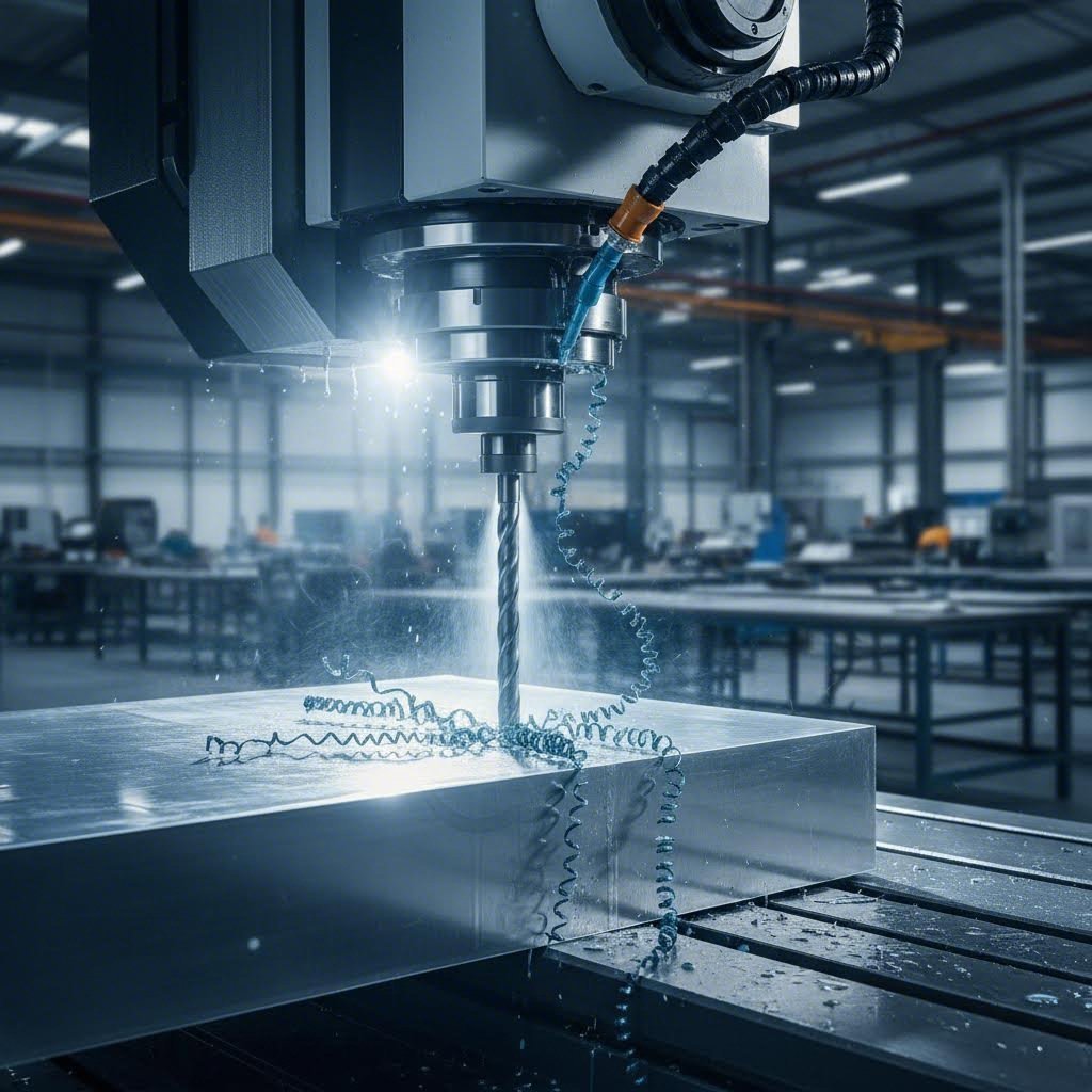
CNC Milling for Sheet Metal Applications
Imagine needing a complex bracket with multiple contoured pockets, precisely angled surfaces, and tight-tolerance features. A metal cutter alone won't get you there. CNC milling steps in as the workhorse for creating intricate geometries that forming and bending operations simply cannot achieve.
CNC milling uses rotating multi-point cutting tools to remove material progressively from sheet metal workpieces. The process excels at creating:
- Flat pockets and recesses — For component nesting or weight reduction
- Complex 3D contours — Including curved surfaces and sculptured profiles
- Precise edge profiles — Chamfers, bevels, and radiused edges
- Thin-wall features — Where dimensional control is critical
For prototyping applications, milling offers exceptional flexibility. You can iterate designs quickly without tooling investments, making it ideal for validation phases. In production scenarios, milling maintains its value for complex geometries that would require expensive progressive die cut machine setups or multiple secondary operations.
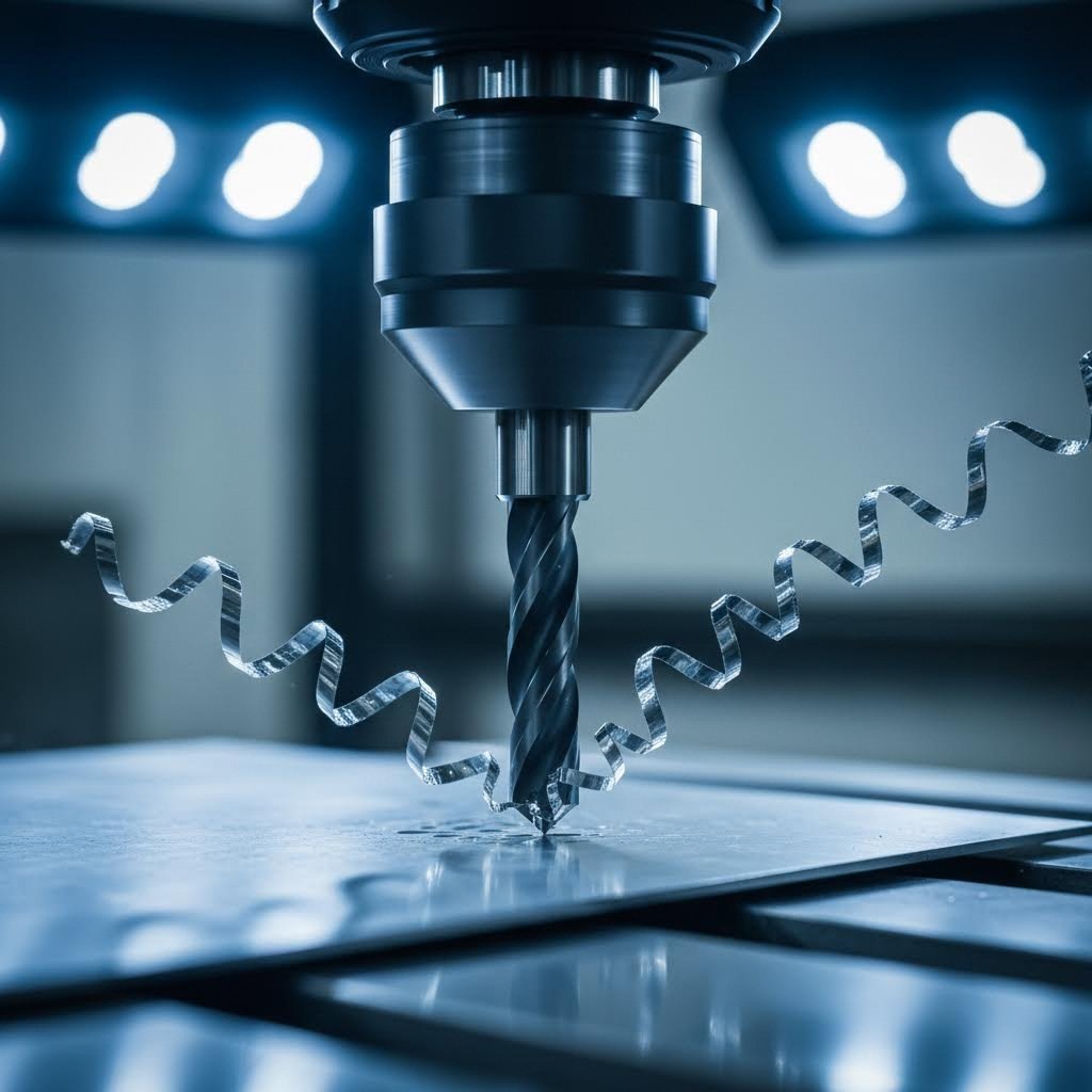
Precision Hole-Making Techniques
Creating holes sounds simple until you need them positioned within thousandths of an inch, threaded to specific standards, or finished to exact diameters. This is where drilling, reaming, and tapping become indispensable.
Drilling initiates hole creation using twist drills or specialized cutting tools. Modern CNC equipment delivers positional accuracy that manual methods cannot match—critical when multiple holes must align across assembled components.
Reaming follows drilling when hole diameter and surface finish requirements exceed what drilling alone achieves. According to industry standards, reamed holes typically achieve tolerances of ±0.0005 inches with superior surface quality compared to as-drilled conditions.
Tapping creates internal threads that enable secure fastener connections. As Xometry's machining resources explain, tapping is the crucial process for creating secure, precise, and reusable threaded connections across all industries. The precision of tapping ensures that threaded connections are strong, secure, and function as intended while resisting the expected shear forces when fasteners are tightened.
CNC tapping on modern equipment continuously monitors the process, with advanced systems detecting issues like excessive torque or tool wear—ensuring consistent thread quality across production volumes.
Surface Finishing Through Grinding and Deburring
Raw machined surfaces rarely meet final part requirements without additional finishing. Grinding and deburring operations bridge the gap between machined condition and functional specification.
Grinding uses bonded abrasive wheels rotating at high speeds against workpiece surfaces. According to OKDOR's surface finishing guide, grinding achieves surface roughness values ranging from Ra 3.2 μm for rough operations down to Ra 0.1 μm for precision work. This makes it particularly effective for:
- Large surface area refinement
- Weld smoothing and blending
- Achieving flatness specifications
- Preparing surfaces for coating or bonding
Deburring removes the sharp edges and material remnants that machining operations leave behind. Linear deburring—an automated process using continuous abrasive belts—efficiently handles straight edges on flat components, achieving surface roughness between Ra 3.2 and Ra 0.4 μm depending on finishing stage.
Process Selection: Prototype vs Production
Choosing the right process depends heavily on your production context. Prototypes benefit from flexible processes with minimal setup—CNC milling and drilling adapt quickly to design changes. Production runs, however, demand efficiency, so process selection shifts toward optimized tooling and automation.
| Process Name | Best Applications | Typical Tolerances | Material Compatibility |
|---|---|---|---|
| CNC Milling | Complex contours, pockets, multi-axis features, prototype iterations | ±0.005" standard; ±0.001" achievable | Aluminum, steel, stainless, brass, copper |
| Drilling | Through-holes, blind holes, pilot holes for tapping | ±0.005" positional; diameter varies by method | All common sheet metals |
| Reaming | Precision holes requiring exact diameter and finish | ±0.0005" diameter typical | Aluminum, steel, stainless steel |
| Tapping | Threaded holes for machine screws and bolts | Class 2B or 3B thread fit per application | All machinable metals; softer metals require care |
| Grinding | Surface finish improvement, flatness, weld smoothing | Ra 0.1-3.2 μm surface roughness | Steel, stainless steel, hardened materials |
| Deburring | Edge quality, burr removal, safety finishing | Ra 0.4-3.2 μm edge finish | All sheet metals |
When evaluating sheet metal machining services, look beyond basic cutting capabilities. The processes outlined here—and CNC integration across all of them—represent what separates precision manufacturing from simple metal cutting. Understanding these distinctions helps you specify requirements accurately and identify providers equipped to deliver the quality your applications demand.
Material Selection Guide for Sheet Metal Machining
You've identified the right processes for your project—but have you considered how material choice affects every machining operation? The metal you select influences cutting speeds, tool life, achievable tolerances, and ultimately, your project's success. Yet many engineers specify materials based solely on end-use requirements without understanding how those materials behave under machining conditions.
Different metals respond dramatically differently to cutting tools. Some machine like butter; others fight back with work hardening and heat buildup. Understanding these characteristics helps you balance performance requirements against manufacturing realities—and avoid costly surprises when quotes arrive.
Aluminum Sheet Machining Considerations
Aluminum sheet metal stands out as the machinist's friend. According to Advanced Integrated Technologies' machinability rating data, wrought aluminum alloys achieve machinability ratings between 3.20 and 4.80—dramatically higher than most other metals. For context, free-machining steel (the baseline at 1.0) machines roughly four to five times slower than common aluminum alloys.
What makes aluminum sheet so cooperative? Several properties work in its favor:
- Low cutting forces — Tools slice through aluminum with minimal resistance, reducing power requirements and tool stress
- Excellent chip formation — Material clears quickly from cutting zones without clogging or rewelding
- High thermal conductivity — Heat dissipates rapidly, preventing thermal damage to both workpiece and tooling
- No work hardening — Unlike stainless steel, aluminum doesn't become harder as you machine it
Common alloys like 6061 and 7075 dominate sheet metal machining applications. The 6061 grade offers excellent machinability with good corrosion resistance—ideal for general-purpose components. When strength requirements increase, 7075 delivers aerospace-grade performance while remaining highly machinable.
However, aluminum's softness creates its own challenges. Burr formation requires attention during drilling and milling operations. Tool geometries and cutting parameters need optimization to prevent material from gumming onto cutting edges—a phenomenon called built-up edge that degrades surface finish and dimensional accuracy.
Stainless Steel Grade Selection
Stainless steel sheet metal presents a more nuanced picture. While it delivers exceptional corrosion resistance and strength, these benefits come with machining trade-offs that demand careful grade selection.
The primary challenge? Work hardening. As cutting tools engage stainless steel, the material in the cutting zone actually becomes harder—sometimes significantly so. This phenomenon affects austenitic grades (300-series) most severely. When tools dwell in the cut or take insufficient depth, they essentially harden the surface for subsequent passes, accelerating tool wear and potentially causing machining failures.
According to the machinability data referenced earlier, austenitic stainless steels like 304 and 316 rate between 0.36 and 0.64—meaning they machine roughly three to four times slower than baseline steel. Free-machining grades like 303 improve this to 0.76, but still lag significantly behind aluminum or carbon steel.
Grade selection strategies for stainless steel sheet include:
- 303 stainless — Contains sulfur additions that enhance machinability; ideal when corrosion resistance matters but welding isn't required
- 304 stainless — General-purpose grade balancing corrosion resistance with reasonable machinability; requires aggressive cutting parameters
- 316 stainless — Superior corrosion resistance for marine or chemical environments; machines similarly to 304 but at higher cost
- 416 stainless — Martensitic grade with excellent machinability (0.88 rating); sacrifices some corrosion resistance for manufacturing efficiency
For applications requiring both galvanized sheet metal aesthetics and stainless-level durability, understanding these trade-offs helps you specify appropriately without over-engineering the solution.
Carbon Steel: The Cost-Effective Workhorse
When corrosion resistance isn't critical, carbon steel delivers excellent value. Low and medium carbon grades machine efficiently with machinability ratings from 0.44 to 0.80—significantly better than stainless alternatives.
Carbon steel's predictable behavior makes it forgiving for less experienced machinists. It produces clean chips, tolerates minor parameter variations, and responds well to standard cutting tools. For high-volume production where parts will receive protective coatings or operate in controlled environments, carbon steel often represents the optimal material choice.
The trade-off? Carbon steel requires post-machining protection. Without coating, plating, or painting, corrosion becomes inevitable. Factor finishing costs into your material decision—sometimes stainless steel's higher material cost balances against eliminated finishing operations.
Specialty Metals: Copper and Brass
When electrical conductivity, thermal performance, or aesthetic requirements drive material selection, copper alloys enter the conversation. Understanding brass vs bronze characteristics—and how both compare to pure copper—helps you specify the right alloy.
Copper alloys span a wide machinability range. Free-machining brass grades (like C360) achieve ratings up to 2.0, making them among the easiest metals to machine. These alloys excel for:
- Electrical contacts and connectors
- Heat exchanger components
- Decorative hardware and fixtures
- Precision instrument parts
Pure copper machines less cooperatively (around 0.68-0.80 rating) due to its softness and tendency to form stringy chips. However, when electrical or thermal conductivity requirements demand pure copper, experienced machinists adjust techniques accordingly.
For architectural applications, corrugated metal designs sometimes incorporate copper alloy sheet for its distinctive appearance and weathering characteristics. These applications typically prioritize aesthetics over machining efficiency.
Understanding Gauge Sizes and Thickness
Material selection doesn't end with alloy choice—thickness matters equally. Sheet metal gauge sizes follow a counterintuitive system where higher numbers indicate thinner material. According to All Metals Fabrication's industry guide, commonly-used sheet metal ranges from 26 gauge (thinner) to 7 gauge (thicker).
Here's where it gets confusing: gauge thickness varies by metal type. Ferrous and non-ferrous metals classified by the same gauge actually have different thicknesses. Most shops measure steel and stainless steel sheet metal by gauge while specifying non-ferrous materials like aluminum sheet by decimal thickness.
For reference, 14 gauge steel thickness measures approximately 0.075 inches (1.9mm), while 11 gauge steel thickness comes in at roughly 0.120 inches (3.0mm). These variations directly impact machining parameters, tooling selection, and process capabilities.
Material Comparison for Machining Applications
| Material Type | Machinability Rating | Common Applications | Key Challenges |
|---|---|---|---|
| Aluminum Alloys (6061, 7075) | 3.00 - 4.50 | Aerospace brackets, electronics enclosures, automotive components, heat sinks | Burr formation, built-up edge on tools, requires sharp tooling |
| Stainless Steel (304, 316) | 0.36 - 0.64 | Food equipment, medical devices, marine hardware, chemical processing | Work hardening, high tool wear, requires rigid setups and aggressive feeds |
| Free-Machining Stainless (303, 416) | 0.76 - 0.96 | Fasteners, fittings, shafts, components not requiring welding | Reduced corrosion resistance vs standard grades, limited weldability |
| Carbon Steel (1018, 1045) | 0.44 - 0.80 | Structural components, brackets, machine parts, high-volume production | Requires corrosion protection, rusts without coating |
| Free-Machining Brass (C360) | 1.60 - 2.00 | Electrical connectors, plumbing fittings, decorative hardware | Soft material requires support, chip evacuation considerations |
| Copper (C110) | 0.68 - 0.80 | Electrical busbars, heat exchangers, grounding components | Stringy chips, gummy cutting behavior, requires specialized tooling |
Selecting the right material balances end-use requirements against manufacturing realities. The highest-performing alloy means nothing if machining costs balloon or lead times extend unacceptably. Work with your sheet metal machining services provider early in the design phase—their material expertise can identify alternatives that satisfy performance requirements while optimizing manufacturability.
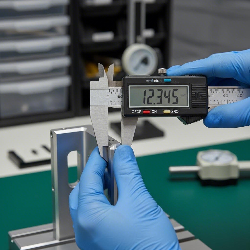
Tolerance Standards and Precision Specifications
You've selected your material and identified the right machining processes—but how precise do your parts actually need to be? This question sits at the heart of every sheet metal machining project, yet it's where most specifications fall short. Tolerances aren't just numbers on a drawing; they're a precision contract that directly impacts cost, manufacturability, and whether your parts function as intended.
According to ADH Machine Tool's comprehensive tolerance guide, applying unnecessarily tight geometric tolerances can significantly extend lead times and increase manufacturing complexity and cost. Conversely, if tolerances range too loosely, quality suffers. Finding that sweet spot requires understanding what tolerances mean, how they're classified, and what factors influence achievable precision.
Understanding Machining Tolerance Classes
Think of tolerances as guardrails around your nominal dimensions. The nominal size represents the center line—the ideal measurement you're targeting. Upper and lower deviations define how far actual parts can stray from that ideal while remaining acceptable. Stay within these boundaries, and your part meets specification; drift outside, and you've got scrap.
International standards like ISO 2768 classify tolerances into grades that balance precision against practicality. These 18 tolerance grades range from IT01 (ultra-precision measuring instruments) down to IT18 (rough castings). For sheet metal machining services, you'll typically work within IT12 through IT14 for general fabrication, while precision machining operations achieve IT5 through IT7.
Here's what those classifications mean practically:
- Fine (f) — Suitable for high-precision parts requiring minimal variation; typical for critical mating surfaces
- Medium (m) — Appropriate for general engineering purposes; balances precision with cost
- Coarse (c) — Used for rough machining processes where exact dimensions aren't critical
- Very Coarse (v) — Applicable for very rough machining or non-critical features
For a 10mm dimension, these classes translate to real numbers: Fine tolerances hold ±0.05mm, Medium allows ±0.1mm, Coarse permits ±0.2mm, and Very Coarse extends to ±0.5mm. That difference between ±0.05mm and ±0.3mm can mean the difference between parts that assemble perfectly and parts requiring rework.
Material thickness significantly affects achievable tolerances. When working with 14 gauge steel thickness (approximately 0.075 inches), tighter tolerances become more challenging than with thicker stock. Similarly, 11 gauge steel thickness (roughly 0.120 inches) provides more stability during machining operations, potentially allowing tighter specifications without cost penalties.
Specifying Precision Requirements
Getting tolerance specifications right on your drawings prevents costly misunderstandings. Every tolerance symbol represents a strategic decision that influences future performance, manufacturing cost, and whether your supplier can actually produce the part economically.
When specifying precision requirements, consider these critical factors:
- Dimensional accuracy — Linear tolerances for length, width, and hole diameters; tighter for mating features, looser for non-critical dimensions
- Positional tolerances — How precisely holes, slots, and features must locate relative to datum references; critical for assembly alignment
- Surface finish requirements (Ra values) — Roughness average measured in micrometers or microinches; Ra 3.2μm for standard machining, Ra 0.8μm for precision work, Ra 0.4μm or finer for critical sealing surfaces
- Flatness specifications — Permissible deviation from a perfectly flat plane; essential for gasket surfaces and mounting interfaces
- Angular tolerances — Typically ±0.5° for bent features; tighter specifications require specialized equipment
According to Beausino's machining tolerance analysis, the relationship between tolerance tightness and manufacturing cost is often nonlinear. As tolerances become increasingly stringent, production costs rise exponentially—not linearly. Holding ±0.001 inches can cost significantly more than ±0.005 inches due to specialized equipment requirements, longer machining times, and more rigorous inspection.
A practical approach? Specify tolerances only where they're essential for function. Use a drill bit size chart or drill size chart as a reference when calling out hole dimensions—standard drill sizes often provide adequate precision without custom tooling. Consider tensile strength requirements when selecting materials, as stronger materials may require tighter specifications to ensure assembly integrity. And always reference a gauge size chart when communicating thickness requirements to avoid confusion between ferrous and non-ferrous standards.
If a tolerance cannot be measured economically and reasonably, it has no business being on the drawing.
This hard-won manufacturing rule highlights an often-overlooked reality: inspection cost is the twin of tolerance cost. Specifying ±0.01mm might take only seconds to type, but verifying that tolerance may require coordinate measuring machines in temperature-controlled environments. Match your tolerance specifications to practical measurement capabilities, and you'll avoid both manufacturing headaches and inspection bottlenecks.
Understanding these tolerance fundamentals prepares you for the next critical step: designing parts that manufacturers can actually produce efficiently. Design guidelines and file preparation requirements build directly on these precision specifications—ensuring your carefully-considered tolerances translate into manufacturable geometry.
Design Guidelines and File Preparation Requirements
You've nailed your tolerances and selected the perfect material—but can your design actually be manufactured? This question separates successful projects from expensive lessons. According to Fictiv's comprehensive DFM guide, it's often said that product design determines 80% of manufacturing cost. Once your design is finalized, engineers have much less flexibility to reduce costs or simplify production.
Design for Manufacturability (DFM) isn't about limiting creativity—it's about ensuring your precision specifications translate into real parts without ballooning costs or extending lead times. Let's explore the essential guidelines that prevent costly redesigns and streamline your path from CAD to finished component.
Design for Manufacturability Essentials
Imagine designing a beautiful bracket only to discover the bend radius you specified causes cracking during forming. Or placing mounting holes so close to edges that material tears during machining. These scenarios play out daily in manufacturing facilities—and they're entirely preventable with proper DFM knowledge.
Several critical design considerations directly impact manufacturability:
Minimum Bend Radii
Every material has a minimum bend radius below which cracking becomes likely. As a general rule, inside bend radius should equal at least one material thickness for ductile materials like aluminum and mild steel. Harder materials or thicker gauges require proportionally larger radii. Specifying radii too tight doesn't just risk cracks—it creates stress concentrations that compromise long-term fatigue performance.
Hole-to-Edge and Hole-to-Bend Distances
According to SendCutSend's design guidelines, placing holes too close to edges or bends leads to tearing, distortion, and misalignment during forming. When material stretches around a bend, nearby holes can elongate or shift, causing assembly problems. A safe rule: keep holes at least 1.5 to 2 times the material thickness away from edges and bends. This simple spacing buffer maintains part strength and preserves hole accuracy throughout forming operations.
Material Grain Direction
Sheet metal isn't uniform in all directions. Rolling processes create grain patterns that affect both strength and forming behavior. Bends made perpendicular to grain direction typically perform better than those parallel to grain. For critical applications, specify grain orientation on your drawings—especially when fatigue resistance or maximum strength matters.
Feature Spacing for Machining Operations
Cutting tools need room to operate. Holes, slots, and machined features placed too closely together create thin walls that deflect during cutting, causing dimensional errors and potential tool breakage. Maintain feature spacing of at least 2-3 times material thickness between adjacent features. This guidance applies equally whether you're cutting plexiglass, aluminum, or steel—tool access and material stability govern these limits.
When considering how to cut plexiglass or similar materials, similar principles apply: adequate spacing prevents heat buildup and material distortion. And if you're wondering how do you cut perspex for prototype housings or covers, the same DFM rules regarding feature spacing and edge distances ensure clean, accurate results.
Common Design Mistakes That Increase Costs
According to EABEL's analysis of fabrication errors, even small design mistakes can lead to costly problems—unnecessary rework, missed deadlines, material waste, and quality failures. Here are the pitfalls experienced designers learn to avoid:
- Over-specifying tolerances — Calling out ±0.001" when ±0.010" would function identically drives costs exponentially higher
- Sharp internal corners — Most cutting tools have finite radii; perfectly sharp inside edges require secondary EDM operations
- Insufficient bend relief — Without proper relief cuts, material has nowhere to flow during bending, causing cracking and bulging
- Ignoring kerf width — Laser and waterjet cutting removes material; failing to account for kerf in your design affects final dimensions
- Missing grain direction callouts — Critical for parts requiring maximum strength or fatigue resistance in specific orientations
- Inadequate tool access — Features that cutters cannot reach require complex fixturing or late-stage design changes
Each mistake compounds through the manufacturing process. A bend relief oversight discovered during forming requires design revision, new programming, and repeated setup—transforming a minor detail into a major delay.
File Preparation Best Practices
Your CAD file is the manufacturing blueprint. Incomplete or improperly formatted files trigger back-and-forth communications, quote delays, and potential misinterpretation. Follow these steps to prepare files that manufacturers can quote and produce efficiently:
- Select appropriate CAD formats — STEP (.stp, .step) files offer universal compatibility and preserve 3D geometry accurately. For 2D cutting, DXF files remain industry standard. Native formats (SolidWorks, Fusion 360, Inventor) work when your manufacturer supports them, but always confirm compatibility before submitting.
- Apply proper dimensioning standards — Use consistent units throughout (decimal inches or millimeters—never mix). Reference critical dimensions from common datums to prevent tolerance stack-up across features. According to SendCutSend's tolerance guidance, dimensioning from a common origin prevents compounding errors that cause assembly problems.
- Include complete tolerance callouts — General tolerances (per ISO 2768 or your company standard) should appear in the title block. Critical dimensions requiring tighter control need individual tolerance specifications. Don't assume manufacturers will guess which dimensions matter most.
- Specify material completely — Include alloy designation (6061-T6, not just "aluminum"), thickness (use a sheet metal gauge chart for ferrous metals or decimal dimensions for non-ferrous), temper condition, and any special requirements like grain direction or certified material.
- Define surface finish requirements — Call out Ra values for machined surfaces and specify finish types (anodized, powder coated, passivated) with color or gloss specifications where applicable.
- Add bend information — For formed parts, include bend direction indicators, specify inside or outside radius measurements, and note whether dimensions apply before or after forming.
- Document secondary operations — Hardware installation, threading, countersinking, and finishing all require specification. Include hole callouts using standard drill chart references where appropriate.
- Implement revision control — Date your files, use revision letters or numbers, and maintain clear documentation of changes between versions. Nothing causes more manufacturing chaos than outdated files entering production.
DFM Review Checklist
Before submitting files for quotation, run through this verification:
| Design Element | Verification Question | Typical Requirement |
|---|---|---|
| Bend Radii | Are inside radii at least equal to material thickness? | IR ≥ 1T for aluminum; IR ≥ 1.5T for stainless |
| Hole-to-Edge Distance | Are holes far enough from edges to prevent tearing? | Minimum 1.5-2x material thickness |
| Hole-to-Bend Distance | Will holes distort during forming? | Minimum 2x material thickness plus bend radius |
| Feature Spacing | Can cutting tools access all features without deflection? | Minimum 2-3x material thickness between features |
| Bend Relief | Are relief cuts included where flanges don't span full width? | Width ≥ 1.5T; depth = bend radius + thickness + 0.020" |
| Internal Corners | Are internal corners radiused for tool access? | Minimum radius = tool radius (typically 0.125" or larger) |
| Tolerances | Are tight tolerances limited to functional features only? | Use standard tolerances unless function demands tighter |
Manufacturers offering comprehensive DFM support will catch issues during quoting—but front-loading this effort accelerates your timeline and demonstrates project readiness. Files that pass DFM review on first submission move to production faster, often qualifying for expedited turnaround options that poorly-prepared projects cannot access.
With design guidelines mastered and files properly prepared, your parts are ready for the manufacturing floor. But machining is only part of the story—surface finishing and secondary operations transform raw machined components into functional, durable products ready for their intended environment.

Surface Finishing and Secondary Operations
Your part just came off the machine—precision holes drilled, contours milled, edges deburred. But is it actually finished? For most applications, the answer is no. Raw machined surfaces rarely meet the corrosion resistance, aesthetic requirements, or durability demands of real-world environments. That's where surface finishing transforms a machined component into a functional, long-lasting product.
Understanding your finishing options isn't just about appearance—it directly impacts part performance, lead time, and total project cost. Yet many engineers treat finishing as an afterthought, discovering too late that their selected treatment adds weeks to delivery or doubles the unit price.
Surface Treatment Options Explained
Different materials require different protection strategies. Aluminum oxidizes naturally, but that thin oxide layer offers minimal protection in harsh environments. Stainless steel resists corrosion inherently, yet machining operations can compromise its passive layer. Carbon steel? It'll rust before your parts reach the customer without proper treatment.
Anodizing for Aluminum Protection
When you need durable protection for aluminum components, anodizing delivers exceptional results. According to Fictiv's comprehensive anodizing guide, this electrochemical process converts the aluminum surface into a thicker, more uniform oxide layer that provides corrosion resistance, wear resistance, and improved appearance—all integrated into the base material rather than applied on top.
Anodized aluminum offers several distinct advantages:
- Integral protection — The anodic layer becomes part of the aluminum itself, not a separate coating that can peel or chip
- Color options — Dyed anodize accepts vibrant colors from black and blue to red, gold, and green
- Enhanced heat dissipation — Anodic coatings increase surface emissivity, improving thermal performance for heat sinks
- Improved adhesion — Paint, adhesives, and lubricants bond more effectively to anodized surfaces
Three main anodizing types serve different applications. Type II (sulfuric acid anodizing) handles most commercial and aesthetic applications with coating thicknesses from 0.0001" to 0.001". Type III hard anodize builds thicker layers—0.001" to 0.004"—for maximum wear resistance on gears, valves, and sliding components. Type I chromic acid anodize, though increasingly restricted due to environmental concerns, remains specified for fatigue-critical aerospace components.
One critical consideration: anodizing causes dimensional growth. Surfaces "grow" approximately 50% of the total coating thickness outward. For precision features, factor this into your design or specify masking for critical dimensions.
Powder Coating for Durability
When you need thick, durable protection with unlimited color options, powder coat finishes excel. Unlike liquid paint, powder coating applies electrostatically-charged dry particles that fuse into a continuous film during oven curing. The result? A finish significantly thicker and more impact-resistant than conventional paint.
Powder coating services work across multiple substrate materials—steel, aluminum, and even some zinc-plated components. The process creates finishes from 2 to 6 mils thick (0.002" to 0.006"), providing excellent protection against scratches, chips, and corrosion. For outdoor equipment, architectural components, and consumer products, powder coating often represents the optimal balance between protection and cost.
Color matching capabilities make powder coating particularly versatile. RAL and Pantone color matching ensures brand consistency across product lines, while textured finishes hide minor surface imperfections that would telegraph through thinner coatings.
Plating Options
Electroplating deposits thin metallic layers onto base materials, combining aesthetic appeal with functional performance. Common plating options include:
- Zinc plating — Sacrificial corrosion protection for steel; economical for high-volume production
- Nickel plating — Wear resistance and corrosion protection; serves as base layer for chrome
- Chrome plating — Decorative bright finish with excellent hardness; available in decorative or hard chrome variants
- Electroless nickel — Uniform coating thickness regardless of geometry; excellent for complex shapes
Plating thicknesses typically range from 0.0001" to 0.002" depending on application requirements. Unlike powder coating, plating maintains tight dimensional control—critical for precision components where thick coatings would interfere with assembly.
Finishing Processes for Durability
Passivation for Stainless Steel
Stainless steel derives its corrosion resistance from a passive chromium oxide layer. But machining operations—particularly those using cutting fluids or carbon steel tooling—can contaminate surfaces with free iron that compromises this protection. Passivation removes these contaminants and restores optimal corrosion resistance.
According to Carpenter Technology's passivation guidance, the process typically involves immersing parts in nitric or citric acid solutions that dissolve embedded iron particles without attacking the stainless steel base material. Proper passivation is verified through humidity testing or copper sulfate solutions that reveal any remaining free iron contamination.
For medical devices, food processing equipment, and marine applications, passivation isn't optional—it's essential for meeting regulatory requirements and ensuring long-term performance.
Finishing Method Comparison
| Finish Type | Compatible Materials | Protection Level | Aesthetic Options |
|---|---|---|---|
| Type II Anodize | Aluminum alloys | Good corrosion and wear resistance; moderate thickness | Wide color range through dyeing; clear, black, colors available |
| Type III Hard Anodize | Aluminum alloys | Excellent wear resistance; thick protective layer | Limited colors; typically dark gray to black |
| Powder Coating | Steel, aluminum, zinc-plated metals | Excellent impact and scratch resistance; thick film | Unlimited colors; gloss, matte, textured finishes |
| Zinc Plating | Steel, iron | Good sacrificial corrosion protection | Clear, yellow, black chromate conversions |
| Nickel Plating | Steel, copper, aluminum (with zincate) | Good wear and corrosion resistance | Bright or matte silver appearance |
| Chrome Plating | Steel, copper, aluminum (with base layers) | Excellent hardness; decorative or functional | Mirror-bright finish; distinctive appearance |
| Passivation | Stainless steel | Restores optimal corrosion resistance | No visual change; maintains original appearance |
Lead Time and Cost Implications
Finishing selection directly impacts your project timeline. Simple processes like passivation add 1-2 days. Anodizing typically requires 3-5 days depending on batch scheduling. Powder coating, with its curing requirements, often adds 3-7 days. Complex multi-step processes—like nickel-chrome plating—can extend lead times by two weeks or more.
Cost follows a similar pattern. Passivation and basic conversion coatings represent minimal cost additions. Anodizing and powder coating fall in the moderate range, with pricing driven by part size and batch quantity. Plating operations, particularly those requiring multiple metal layers, command premium pricing due to process complexity and chemical management requirements.
Smart project planning considers finishing requirements from the start. Specifying your finish during the design phase—not after machining completes—allows manufacturers to optimize scheduling and identify the most cost-effective approach for your specific requirements.
With surface finishing options understood, you're equipped to specify complete parts rather than just machined blanks. The next consideration? Determining whether your project calls for prototype quantities or production volumes—a decision that fundamentally shapes your manufacturing approach and partner selection.
Choosing Between Prototyping and Production Services
Your design is finalized, tolerances specified, and finish selected—but one critical question remains: should you prototype first, or jump straight into production? This decision shapes everything from your budget to your timeline to the quality of your final product. Get it wrong, and you're either overspending on low-volume runs or discovering design flaws after committing to expensive tooling.
According to EABEL's manufacturing analysis, the biggest cost factor in sheet metal manufacturing is tooling amortization. Mass production requires expensive dies, so the real savings appear only when those costs are spread across large quantities. Understanding this relationship helps you navigate the prototyping-to-production transition without burning budget or time.
Prototyping Requirements vs Production Runs
Think of prototyping as your manufacturing dress rehearsal. Instead of committing to expensive tooling and high-volume production, you create sample components first—testing everything from how the part looks and feels to whether it actually works in your application.
Rapid prototyping excels in specific scenarios:
- Early design validation — Testing concepts before investing in production tooling
- Small batch requirements — Quantities from 1 to a few hundred parts
- Frequent design iterations — Projects requiring multiple revisions based on testing feedback
- Proof-of-concept parts — Demonstrating feasibility to stakeholders or customers
Mass production makes sense when different conditions apply:
- High-volume needs — Thousands or millions of identical parts
- Mature, stable designs — Products where specifications won't change
- Tight tolerance requirements — Applications demanding extreme consistency across all units
- Cost-per-unit optimization — Projects where tooling investment pays off through volume
The crossover point—where production tooling becomes more economical than prototyping methods—typically occurs between a few dozen to a few hundred parts, depending on material and part complexity. According to Manufyn's prototyping guide, miscalculating this threshold can lead to overspending on tooling too early or relying on slow, costly prototyping for mid-volume runs.
Design Flexibility Considerations
Rapid prototyping supports quick design cycles, making it ideal for early-stage development. Engineers can test, adjust, rework, and even re-cut metal parts within days. This speed helps teams validate concepts before investing in production tooling—catching the bracket that doesn't fit or the mounting hole that's positioned wrong before those errors multiply across thousands of parts.
In mass production, design changes become far more difficult. Any modification may require die rework or a completely new die, increasing both time and cost exponentially. This is why completing thorough DFM checks before moving to mass production is essential—ensuring the design is optimized for tooling reduces rework and keeps the production timeline on track.
Optimizing Your Manufacturing Approach
Choosing the right path requires evaluating multiple factors simultaneously. Here's the decision framework that separates successful projects from costly mistakes:
Key Decision Factors
- Quantity requirements — How many parts do you need now? How many will you need over the product lifecycle? Low volumes favor prototyping methods; high volumes justify tooling investment.
- Timeline constraints — Prototype parts can arrive in days; production tooling takes weeks or months to develop. If you're racing to market, starting with rapid prototyping validates your design while tooling development proceeds in parallel.
- Quality specifications — Prototyping delivers strong functional quality, but tolerances can vary depending on machine setup and process complexity. Mass production with hardened tooling produces extremely consistent tolerances—essential when thousands of identical parts must meet strict quality standards.
- Budget parameters — Prototyping avoids upfront tooling costs but carries higher per-unit pricing. Production spreads tooling investment across volume, driving per-unit costs down dramatically at scale.
The Hybrid Approach
Many successful companies follow a staged path: start with rapid prototyping for design validation, move to soft or bridge tooling for mid-volume runs, and scale into full production as demand and design stability increase. This approach minimizes risk at each stage while building confidence in both the design and the manufacturing process.
According to EABEL's analysis, manufacturers sometimes use bridge tooling or soft tooling to test designs before committing to full production—a strategic middle ground that validates manufacturability without the full investment of hardened production dies.
Lead Time Expectations
Understanding realistic timelines helps you plan effectively. For straightforward parts, rapid prototyping typically delivers finished samples in 3-5 days from CAD file submission. Complex assemblies might take 1-2 weeks. Production tooling development, by contrast, often requires 4-8 weeks before first articles—and any design changes restart significant portions of that timeline.
This timing difference explains why manufacturers offering rapid turnaround capabilities—such as 5-day prototyping services—provide strategic advantages for product development teams. Shaoyi, for example, bridges prototyping to production with both 5-day rapid prototyping and automated mass production capabilities, enabling design validation before committing to production tooling. For automotive applications where IATF 16949 certification matters, their automotive stamping parts services demonstrate how certified manufacturers support the full development lifecycle.
Fast quote turnaround also accelerates project planning. When evaluating suppliers, look for 12-hour quote response capabilities—this responsiveness signals operational efficiency that typically extends throughout the manufacturing relationship.
Cost Optimization Strategies
Smart project management optimizes costs across the entire development cycle, not just individual phases:
- Validate before tooling — Investing in prototypes catches design issues when corrections cost hundreds, not tens of thousands
- Right-size your quantities — Order what you need now; don't over-commit to volumes based on optimistic forecasts
- Consider total cost — Include finishing, inspection, shipping, and potential rework when comparing prototype vs. production economics
- Plan for iteration — Budget for 2-3 prototype rounds; first designs rarely achieve perfection
Companies searching for steel fabrication partners or metal fabricators near me often focus solely on quoted prices. But the real cost comparison includes development time, revision cycles, and the expense of discovering problems late in the process. A slightly higher-priced supplier offering comprehensive DFM support and rapid iteration often delivers lower total project cost than the lowest bidder without those capabilities.
Volume Threshold Guidelines
While exact crossover points depend on part complexity and material, these general thresholds guide initial planning:
| Volume Range | Recommended Approach | Typical Lead Time | Cost Characteristics |
|---|---|---|---|
| 1-25 parts | Rapid prototyping | 3-7 days | Higher per-unit; no tooling cost |
| 25-500 parts | Prototype methods or soft tooling | 1-3 weeks | Moderate per-unit; minimal tooling |
| 500-5,000 parts | Bridge tooling or early production | 4-6 weeks | Decreasing per-unit; moderate tooling |
| 5,000+ parts | Full production tooling | 6-12 weeks initial | Lowest per-unit; significant tooling investment |
When comparing options from services like SendCutSend, OSHCut, or other fabrication shops near me, evaluate not just current pricing but their ability to support your growth from prototype through production. Partners who can scale with your project eliminate the complexity of transitioning between suppliers—and the quality variations that often accompany such transitions.
With your manufacturing approach determined, the final piece falls into place: selecting a partner equipped to execute your vision. The right sheet metal machining services provider brings more than equipment—they bring expertise, certifications, and process capabilities that transform your specifications into precision components.
Selecting the Right Sheet Metal Machining Partner
You've designed your parts, specified your tolerances, and determined your production approach—but none of that matters if you partner with the wrong manufacturer. The gap between a capable supplier and an exceptional one often means the difference between on-time, on-spec delivery and costly delays, quality escapes, and frustrating rework cycles.
According to Atlas Manufacturing's OEM fabrication guide, choosing the right OEM sheet metal fabrication provider is crucial to the success of a project. This selection process deserves the same rigor you applied to your design specifications—because even perfect drawings become scrap in the wrong hands.
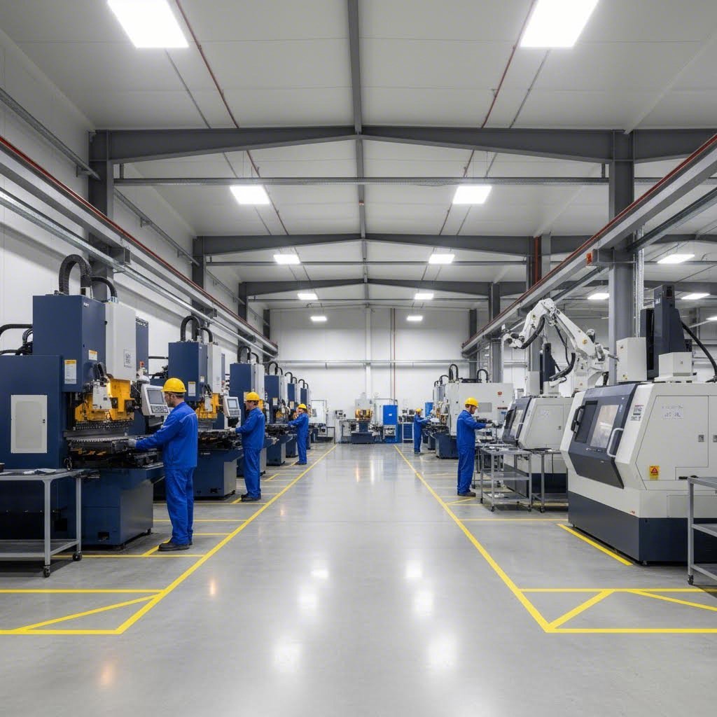
Evaluating Provider Capabilities
Not all steel fabricators are created equal. Some excel at high-volume production runs; others specialize in prototype flexibility. Some handle only basic cutting operations; others integrate machining, forming, and finishing under one roof. Understanding what capabilities matter for your specific project helps you filter the field efficiently.
When you search for sheet metal near me or metal fabricators near me, the proximity matters less than capability alignment. A supplier across the country with the right equipment and certifications often outperforms a local shop lacking essential capabilities. Focus your evaluation on these critical areas:
Equipment and Technology
Modern CNC equipment delivers precision that older machines simply cannot match. Ask potential suppliers about their machine vintages, maintenance programs, and technology investments. Providers running state-of-the-art equipment typically maintain tighter tolerances with better repeatability—critical when you're specifying demanding features on 316 stainless steel components or complex aluminum welding assemblies.
Beyond individual machines, evaluate integrated capabilities. Can the supplier handle your complete part requirements—machining, forming, welding, and finishing—or will your components travel between multiple facilities? Each handoff introduces quality risk and extends lead times.
Material Inventory and Sourcing
Suppliers maintaining robust material inventories respond faster to orders and typically offer better pricing through volume purchasing. Ask about standard stock programs, lead times for specialty materials, and relationships with certified material suppliers. For critical applications, verify their ability to provide material certifications and traceability documentation.
Welding Capabilities
If your parts require welding, understanding the difference between mig vs tig welding capabilities matters. TIG welding delivers superior precision and cleaner aesthetics for thin materials and visible joints—essential for stainless steel and aluminum work. MIG welding offers faster production speeds for thicker materials and structural applications. When evaluating tig vs mig welding capabilities, ensure your supplier matches the right process to your specific material and quality requirements.
Quality Certifications That Matter
Certifications aren't just wall decorations—they represent verified commitments to quality systems, process controls, and continuous improvement. According to Tempco Manufacturing's quality documentation, advanced quality certifications provide the knowledge and peace of mind that suppliers are providing the highest quality service in the sheet metal industry.
ISO 9001:2015
This foundational certification requires organizations to define and follow a quality management system that is both appropriate and effective while also requiring them to identify areas for improvement. Think of ISO 9001 as the baseline—suppliers without it haven't demonstrated basic quality system discipline.
IATF 16949 for Automotive Applications
If your components serve automotive applications, IATF 16949 certification isn't optional—it's essential. This automotive-specific standard builds on ISO 9001 with additional requirements for defect prevention, variation reduction, and supply chain quality management. Automotive OEMs increasingly require IATF 16949 certification throughout their supply chains.
Shaoyi exemplifies what automotive-grade certification looks like in practice. Their IATF 16949-certified operations deliver the quality systems automotive applications demand, while their comprehensive DFM support catches design issues before they become production problems. For projects requiring automotive-certified sheet metal services, their automotive stamping parts capabilities demonstrate the complete package of certification, capability, and responsiveness that serious automotive suppliers require.
Industry-Specific Certifications
Beyond general quality certifications, specialized standards apply to specific industries. AS9100D serves aerospace applications with requirements for risk management, configuration control, and product safety. ISO 13485 addresses medical device manufacturing with emphasis on regulatory compliance and patient safety. Verify that potential suppliers hold certifications relevant to your application.
Supplier Evaluation Checklist
Before committing to a sheet metal machining services provider, work through this systematic evaluation:
- Verify certifications independently — Request copies of current certificates and confirm validity through issuing registrars. Certifications expire, and some suppliers display outdated credentials.
- Request material certifications — For critical applications, suppliers should provide mill certifications documenting material chemistry, mechanical properties, and traceability. This documentation proves essential for regulated industries and quality investigations.
- Review quality inspection processes — Ask about in-process inspection, final inspection protocols, and statistical process control implementation. Suppliers using CMM (coordinate measuring machine) verification and documented inspection plans demonstrate quality commitment beyond basic visual checks.
- Assess DFM support availability — Comprehensive DFM support prevents costly design revisions downstream. According to Atlas Manufacturing's analysis, collaborating closely with the fabrication provider during the design phase can help identify potential design improvements that enhance manufacturability and reduce production costs. Suppliers offering proactive DFM review save you time and money.
- Confirm lead time reliability — Request references and ask specifically about on-time delivery performance. A supplier quoting aggressive lead times means nothing if they consistently miss commitments. Look for providers with rapid quote turnaround—12-hour response times signal operational efficiency that typically extends throughout the relationship.
- Evaluate communication responsiveness — How quickly do they respond to inquiries? Are technical questions answered thoroughly? Communication patterns during quoting typically predict communication during production.
- Review capacity and scalability — Can the supplier handle your current volumes? More importantly, can they scale with your growth? Switching suppliers mid-program introduces risk and disruption.
- Investigate secondary operation capabilities — Parts requiring finishing, hardware installation, or assembly benefit from single-source suppliers who control the entire process.
The Value of DFM Support
Design for manufacturability support deserves special emphasis in your evaluation. According to industry analysis, product design determines approximately 80% of manufacturing cost—decisions made during design lock in costs that manufacturing cannot easily reduce.
Suppliers offering comprehensive DFM review catch issues early:
- Tolerances that drive unnecessary cost without functional benefit
- Features that require secondary operations when simpler alternatives exist
- Material specifications that complicate sourcing or machining
- Bend sequences that create tooling access problems
- Hole placements that risk distortion during forming
This proactive approach transforms the supplier relationship from order-taker to manufacturing partner. Rather than simply building what you specify—including your mistakes—DFM-focused suppliers help you specify parts that are both functional and economical to produce.
Shaoyi's comprehensive DFM support exemplifies this partnership approach. Combined with their 12-hour quote turnaround, they enable efficient project planning where design optimization happens before production commitment—not after costly tooling investments.
Making Your Selection
The right sheet metal machining partner brings more than equipment—they bring expertise, process discipline, and commitment to your success. Evaluate candidates against your specific requirements, prioritizing certifications and capabilities that match your application. Verify claims through references and facility assessments when project scale warrants.
Remember that the lowest quote rarely delivers the lowest total cost. Factor in quality consistency, lead time reliability, DFM support value, and communication responsiveness. A slightly higher-priced supplier with superior capabilities and service often delivers better total value than the apparent low bidder who lacks the systems, certifications, or expertise your project demands.
Whether you're sourcing prototype quantities or scaling to production volumes, the evaluation framework outlined here positions you to select partners who transform your specifications into precision components—on time, on spec, and ready for their intended application.
Frequently Asked Questions About Sheet Metal Machining Services
1. What are the 5 sheet metal operations?
The five primary sheet metal operations include shearing (cutting straight lines), blanking (cutting complete shapes from stock), punching (creating holes), bending (forming angles and curves), and drawing (creating 3D shapes from flat stock). Beyond these forming operations, sheet metal machining services add precision processes like CNC milling, drilling, reaming, tapping, and grinding to achieve tighter tolerances and complex geometries that forming alone cannot deliver.
2. Can CNC machines cut sheet metal?
Yes, CNC machines excel at cutting and machining sheet metal with exceptional precision. CNC laser cutting melts or vaporizes material for intricate designs, while CNC milling uses rotating cutting tools to remove material for complex contours and pockets. These computer-controlled processes achieve tolerances as tight as ±0.001 inches, making them ideal for precision components in automotive, aerospace, and electronics applications.
3. How much does metal fabrication cost per hour?
Metal fabrication and welding services typically range from $70 to $130 per hour, depending on complexity and location. However, sheet metal machining services often quote per-part rather than hourly rates, factoring in material costs, machining time, tolerances, and finishing requirements. For accurate pricing, submit CAD files to manufacturers offering rapid quote turnaround—some providers like Shaoyi deliver quotes within 12 hours.
4. What is the difference between sheet metal machining and fabrication?
Sheet metal machining is a subtractive process that removes material using CNC milling, drilling, and grinding to achieve precise geometries and tight tolerances. Sheet metal fabrication, by contrast, transforms flat stock through forming, bending, and joining operations without significant material removal. Many projects require both disciplines—fabrication creates the basic shape while machining adds precision features like threaded holes and exact dimensions.
5. What certifications should I look for in a sheet metal machining provider?
ISO 9001:2015 certification establishes baseline quality management systems. For automotive applications, IATF 16949 certification is essential, requiring defect prevention and supply chain quality controls. Aerospace projects need AS9100D certification, while medical device components require ISO 13485. Always verify certifications independently through issuing registrars and request material certifications for traceability on critical components.