 Small batches, high standards. Our rapid prototyping service makes validation faster and easier —

Trimming Stamped Automotive Parts: Engineering Guide & Methods
TL;DR
Trimming stamped automotive parts is the critical secondary operation where excess material—known as the addendum or offal—is removed from a formed component to achieve its final dimensional profile. Occurring typically after the deep draw phase, trimming transforms a rough, binder-held shape into a precision part ready for assembly. Manufacturers primarily utilize two methods: mechanical trim dies for high-volume efficiency (using cam-driven or pinch actions) and 5-axis laser cutting for prototypes, low-volume runs, or hardened boron steels. Optimizing this stage is essential for preventing defects like burrs and iron filings while managing scrap costs.
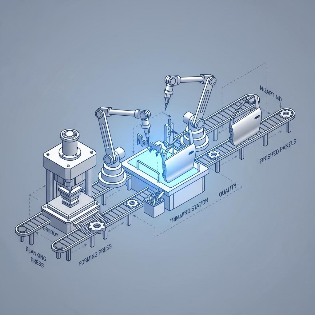
The Role of Trimming in the Automotive Stamping Workflow
In the hierarchy of automotive metal stamping, trimming serves as the definitive bridge between form creation and final detailing. To understand its function, one must first recognize the mechanics of the drawing process. When a flat sheet (blank) is drawn into a 3D shape—such as a door panel or fender—extra material is required around the perimeter. This material, held by the binder ring, controls the flow of metal into the die cavity to prevent wrinkles and splits. Once the drawing is complete, this holding material becomes known as addendum or offal and serves no further functional purpose.
Trimming removes this excess to reveal the part's net shape. It is rarely a standalone process; instead, it is integrated into a larger transfer die or progressive die sequence. Typically, the workflow proceeds as follows:
- Blanking: Cutting the initial sheet layout.
- Drawing: Forming the complex 3D geometry (creating the addendum).
- Trimming: Precision removal of the addendum.
- Flanging/Piercing: Bending tabs or punching holes for assembly.
The precision of the trim line is paramount. A deviation of even a few microns can affect subsequent operations like flanging or hemming, where the edge is folded over to create a safe, smooth finish on parts like hoods and doors. For engineers, the choice of trimming method determines not only the part's tolerance but also the tooling budget and production scalability.
Method 1: Mechanical Die Trimming (High Volume Standard)
For mass production—runs exceeding 100,000 units annually—mechanical trimming is the industry standard. This method uses hard tooling made from hardened tool steel or carbide to shear the metal in a single press stroke. The mechanics involve a shearing action where a moving punch pushes the metal past a stationary die button, fracturing the material within a controlled clearance zone.
Engineers generally select between two mechanical approaches based on the part's geometry and edge quality requirements:
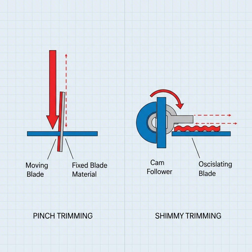
- Pinch Trimming: This method is often used for drawn shells or cup-shaped parts. The trimming is performed by "pinching" the material against a vertical wall. While cost-effective and simpler to maintain, pinch trimming can leave a slight step or thinning at the trim line, which may not be acceptable for Class-A exterior surfaces.
- Shimmy (Cam) Trimming: For high-precision automotive components, cam-driven trimming is preferred. Here, driver blocks convert the vertical motion of the press into horizontal or angled cutting strokes. This allows the die to trim complex, contoured edges perpendicular to the metal surface, resulting in a cleaner edge with minimal burrs. According to The Fabricator, achieving the correct cutting clearance—typically 10% of the material thickness—is critical to preventing premature tool wear.
Pros: Unmatched cycle times (seconds per part); extremely consistent dimensions; lower variable cost per unit.
Cons: High capital expenditure (CapEx) for tooling; expensive and slow to modify if design changes occur.
Method 2: 5-Axis Laser Trimming (Flexibility & Prototyping)
As automotive designs shift toward high-strength, lightweight materials, mechanical trimming faces limitations. Ultra-high-strength steels (UHSS) and hot-stamped boron steel parts are often too hard to be trimmed economically with traditional dies, as they would cause rapid tool failure. Enter 5-axis laser trimming.
Laser trimming utilizes a focused beam of light to melt and sever the material. A multi-axis robotic arm guides the cutting head around complex 3D contours without physical contact. This method eliminates the need for hard tooling, allowing for instant implementation of engineering changes (ECOs) simply by updating the CNC program.
This technology is vital for two specific scenarios:
- Rapid Prototyping: Before committing to expensive hard dies, engineers use laser trimming to validate part geometry and fit-up.
- Hot Stamping: For safety-critical parts like B-pillars formed at high temperatures, the material hardens immediately. Laser trimming is the only viable option to cut these hardened components without shattering conventional trim dies.
While laser trimming offers zero tooling costs, it has a significantly higher operational cost (OpEx) due to slower cycle times. A mechanical press might trim a fender in 4 seconds; a laser might take 90 seconds. However, for manufacturers bridging the gap between prototype and production, this flexibility is invaluable. Partners like Shaoyi Metal Technology leverage this duality, offering solutions that scale from 50-piece prototype runs (using flexible cutting) to millions of IATF 16949-certified mass-produced parts using 600-ton press lines.
Common Trimming Defects & Troubleshooting
Quality control in trimming is dominated by the battle against edge defects. Even minor imperfections can lead to assembly failures or safety hazards for line workers. Troubleshooting usually focuses on three primary culprits: burrs, iron filings, and distortion.
1. Burrs and Rollover
A burr is a sharp, raised edge, while rollover is the rounded edge on the opposite side. These are natural byproducts of shearing but must be kept within tolerance. Excessive burr height is almost always caused by improper cutting clearance. If the gap between the punch and die is too large, the metal tears rather than shears, creating large burrs. If the gap is too tight, the tooling wears out prematurely. Regular sharpening and shim adjustments are the standard fix.
2. Iron Filings (Slivers)
Loose particles of metal, or "slivers," can detach during trimming and fall into the die. If these filings land on the next part during a forming operation, they create pimples or dents in the surface—a disaster for cosmetic Class-A panels. Solutions include incorporating vacuum scrap removers in the die design and ensuring trim steels are sharp to prevent material crumbling.
3. Distortion and Springback
Releasing the tension in a drawn part during trimming can cause the metal to spring back or twist, losing its dimensional accuracy. This is particularly common in high-tensile steels. To counteract this, engineers use pressure pads to hold the part firmly during the cut and may design the trim line intentionally "off" by a calculated amount to account for the springback effect.
Scrap Management & Process Economics
The business side of trimming revolves around offal management. Since the trimmed material is scrap, it represents lost value. However, intelligent process engineering can minimize this loss. Nesting software is used during the blanking phase to arrange parts on the coil strip in a way that minimizes the addendum required, effectively reducing the amount of material that needs to be trimmed later.
Physical removal of scrap is also a logistical challenge. In high-speed progressive dies, scrap chutes and shaker conveyors must efficiently clear the offal to prevent "double hits"—where scrap blocks the die, causing catastrophic tool damage. For stamped automotive parts, the cost of the trim die is often justified not just by the part quality, but by the reliability of its scrap ejection system, which ensures uninterrupted uptime.

Conclusion
Trimming is more than just a cutting operation; it is the defining moment where a sheet of metal becomes a dimensionally accurate automotive component. Whether utilizing the brute force and speed of mechanical trim dies for high-volume body panels or the surgical precision of 5-axis lasers for hardened safety structures, the goal remains the same: a clean, burr-free edge within strict tolerances. As automotive materials evolve toward harder, lighter alloys, the technologies for trimming continue to advance, blending traditional mechanical principles with modern digital flexibility.
Frequently Asked Questions
1. What are the 7 steps in the stamping method?
While variations exist, the standard 7-step stamping process typically includes: Blanking (cutting the initial shape), Piercing (punching holes), Drawing (forming the 3D shape), Bending (creating angles), Air Bending (forming without bottoming out), Bottoming/Coining (stamping for precision and strength), and finally Pinch Trimming (removing excess material from the formed part).
2. What is the difference between shearing and trimming?
Shearing is a broad term for cutting metal along a straight line, often used to create the initial blank from a coil. Trimming is a specific type of shearing operation performed on a 3D formed part to remove the irregular edges (addendum) and achieve the final perimeter profile. Trimming typically requires complex, contoured dies rather than straight blades.
3. Why is "addendum" material needed if it just gets trimmed off?
The addendum acts as a handle for the binder ring to grip during the drawing process. Without this extra material, the metal would flow uncontrollably into the die cavity, resulting in severe wrinkles, tears, and thinning. The addendum ensures the metal stretches evenly over the punch, sacrificing itself to ensure the quality of the final part.