 Small batches, high standards. Our rapid prototyping service makes validation faster and easier —

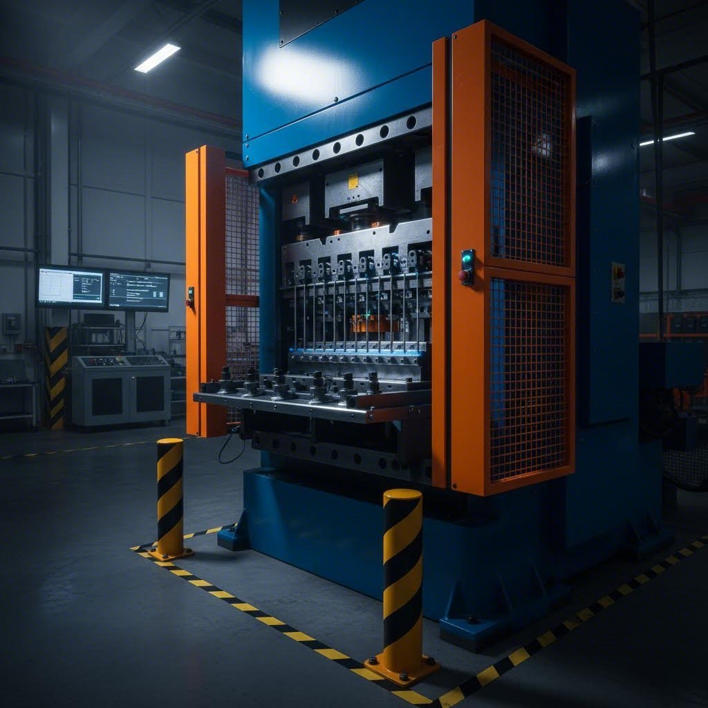
Die Protection System Setup: Stop Costly Crashes Before They Happen
Understanding Die Protection Systems and Their Critical Role
Imagine this scenario: It's the middle of a high-volume production run, and suddenly you hear that unmistakable sound of metal grinding against metal. A mispositioned part just crashed into your progressive die, causing catastrophic damage. The press goes down. Your tool and die maker scrambles to assess the damage while production schedules collapse around you. Hours turn into days of downtime, and repair costs climb into the tens of thousands.
This nightmare scenario plays out in stamping facilities every day. Without proper safeguards, a single missed slug, short feed, or part stuck in the die can destroy weeks of work and derail your entire operation. That's exactly why a robust die protection system setup is no longer optional—it's essential for any competitive stamping operation.
Why Die Protection Matters in Modern Stamping Operations
A die protection system acts as your press's first line of defense against costly crashes. At its core, this technology uses strategically placed sensors to monitor critical events during each stroke cycle. These sensors detect whether parts have ejected properly, materials have fed correctly, and all die components are positioned where they should be. When something goes wrong, the system stops the press before damage occurs.
Think of it as a quality system and management solution for your tooling investment. Every tool & die in your facility represents significant capital, and protecting that investment directly impacts your bottom line. Modern stamping operations running at high speeds simply cannot rely on operator observation alone—events happen too fast for human reaction.
Facilities that invest time in proper die protection system setup consistently report first-pass approval rates 15-25% higher than those rushing through installation. The setup process itself is where protection success is determined.
What This Setup Guide Covers
This guide bridges a critical gap in available resources. You'll find plenty of high-level articles explaining why die protection matters, and you'll find vendor-specific technical manuals buried in jargon. What's missing is a comprehensive, vendor-agnostic walkthrough that takes you from initial assessment through verification—and that's exactly what we're providing.
Whether you're a seasoned die maker installing your hundredth system or an engineer setting up your first protection scheme, this guide covers:
- Pre-installation assessment and planning procedures
- Sensor selection based on your specific application needs
- Proper placement and installation techniques
- Calibration and parameter configuration
- Integration with press controls and PLCs
- Troubleshooting common issues
- Training protocols and ROI measurement
By the end, you'll have the practical knowledge to implement effective die protection—whether you're working with a brand-new system or upgrading legacy equipment. Let's ensure your next tool and die investment stays protected from day one.
Pre-Installation Assessment and Planning Phase
Before you install a single sensor or run a foot of cable, there's critical groundwork that determines whether your die protection system setup succeeds or fails. This assessment phase is where many operations stumble—they rush toward installation without fully understanding their unique requirements. The result? Sensors in wrong positions, missed detection points, and systems that trigger nuisance stops or worse, fail to catch actual problems.
Taking time upfront to evaluate your dies, presses, and production environment pays dividends throughout the life of your protection system. Let's walk through exactly what this assessment should cover.
Conducting a Thorough Die and Press Assessment
Start by examining your tooling closely. Every die presents unique protection challenges based on its complexity, the materials it processes, and its historical failure patterns. A simple blanking die requires a fundamentally different protection approach than a complex progressive die with dozens of stations.
When analyzing your dies, consider these critical factors:
- Die complexity and station count: Progressive dies with multiple stations need sensors at various detection points, while single-operation dies may only require part-out and stock-feed monitoring
- Material characteristics: Different steel grades behave differently during forming—high yield strength materials present greater risk of stuck parts and slugs
- Stroke rates: Higher speeds demand faster sensor response times and tighter timing windows
- Part geometry: Complex shapes may require multiple sensors to confirm proper ejection
- Historical failure points: Review maintenance records to identify where problems typically occur—this is where your protection priorities should focus
Press compatibility deserves equal attention. Your protection controller must communicate seamlessly with your press controls. Check voltage requirements, available I/O connections, and mounting space. Older mechanical presses may need additional hardware to provide the crankshaft position signals that modern die protection systems require for timing-based monitoring.
Understanding your material's yield point is essential when evaluating protection needs. Materials approaching their formability limit diagram boundaries during processing are more likely to cause issues like tearing, wrinkling, or incomplete forming—all scenarios your protection system should detect. The yield point for steel varies significantly across grades, affecting how aggressively you can form parts and what failure modes you need to monitor.
Documenting Your Protection Requirements
Thorough documentation transforms your assessment findings into an actionable protection plan. This step is especially critical when upgrading from older systems, where you can learn from existing protection gaps while preserving what works.
Create a protection requirements document for each die that includes:
- Die identification: Part numbers, die numbers, and associated press assignments
- Critical detection points: Where sensors must monitor—part ejection, slug clearing, strip progression, pilot engagement
- Failure history: Documented incidents of crashes, misfires, or near-misses with root cause analysis
- Current protection status: Existing sensors, their conditions, and any known deficiencies
- Production parameters: Normal stroke rates, material specifications, and yielding force requirements
- Environmental factors: Lubricant exposure, debris accumulation patterns, temperature variations
For new installations, you're building this documentation from scratch based on die design and anticipated failure modes. For upgrades, you have the advantage of operational history—use it. Talk to operators and maintenance technicians who work with these dies daily. They know where problems occur even if those issues never made it into formal records.
Prioritize your protection points based on risk. Not every potential failure carries equal consequences. A stuck slug in a critical area could destroy the entire die, while a minor ejection delay might only cause a quality issue. Allocate your sensors and monitoring attention accordingly.
With your assessment complete and requirements documented, you're ready to select the right sensors for each application—a decision that depends heavily on what you've learned during this planning phase.
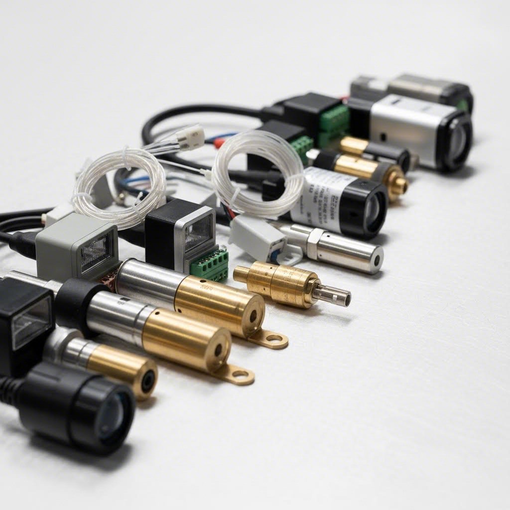
Sensor Selection and Technology Comparison
Choosing the right sensors is where your die protection system setup transitions from planning to tangible protection. Think of sensors as your system's eyes and ears—select the wrong ones, and you're essentially asking the system to work blindfolded. The sensor technologies you choose must align with your specific applications, environmental conditions, and detection requirements identified during your assessment phase.
With dozens of sensor types available, how do you determine which ones belong in your protection scheme? Let's break down the options and match them to real-world applications.
Matching Sensor Types to Your Application Needs
Different monitoring tasks demand different sensor technologies. Here's where understanding your die operations pays off—each sensor type excels in specific scenarios while struggling in others.
Proximity sensors form the backbone of most die protection systems. These workhorses detect the presence or absence of metal objects without physical contact. Inductive proximity sensors respond to ferrous metals and work reliably even in harsh environments with lubricants and debris. You'll use them for detecting part ejection, monitoring strip position, and verifying die component locations.
Part-out sensors confirm that finished parts have actually left the die area before the next stroke begins. A part remaining in the die during the downstroke causes catastrophic damage. These sensors typically mount outside the die opening and detect parts as they exit—whether dropping through a chute or being transferred by automation.
Stock feed sensors verify that material has advanced the correct distance between strokes. In progressive dies, improper feed creates a cascade of problems: pilots can't engage, punches hit in wrong locations, and the entire strip can jam. Feed sensors work alongside your press's feed equipment to ensure every stroke starts with material properly positioned.
Specialized sensors address unique detection challenges. Photoelectric sensors use light beams to detect parts—ideal when you're working with aluminum alloys or other non-ferrous materials that inductive sensors can't reliably detect. Fiber optic sensors reach into tight spaces where standard sensors won't fit. Touch sensors provide positive confirmation of part presence through physical contact when non-contact methods prove unreliable.
When processing materials with hot dip galvanized zinc coating, sensor selection requires extra consideration. The coating thickness can affect detection reliability with some proximity sensors, potentially requiring sensitivity adjustments or alternative technologies.
Critical Factors in Sensor Selection
Beyond matching sensor types to general applications, several critical factors influence your final selections. Getting these right determines whether your protection system catches problems reliably or generates frustrating false alarms.
Detection range and sensing distance must match your application geometry. A sensor with insufficient range won't reliably detect your target, while excessive range may cause false triggers from adjacent components. Most proximity sensors offer adjustable sensitivity, but starting with appropriate base specifications simplifies setup.
Response time becomes critical at higher stroke rates. Your sensor must detect the condition, send its signal, and allow the controller to process and respond—all within the available timing window. For presses running above 100 strokes per minute, every millisecond matters.
Environmental resilience often determines long-term reliability. Stamping environments are punishing—lubricant spray, metal particles, temperature swings, and vibration all attack sensor performance. Look for sensors with appropriate IP ratings and housings designed for industrial environments. Operations involving spin forming or other specialized processes may generate additional debris or require sensors positioned in challenging locations.
The following table provides a comprehensive comparison to guide your sensor selection decisions:
| Sensor Type | Best Applications | Detection Range | Environmental Considerations | Typical Use Cases |
|---|---|---|---|---|
| Inductive Proximity | Ferrous metal detection, part presence, component position | 1-30mm typical | Excellent resistance to oils and coolants; debris buildup requires periodic cleaning | Part ejection verification, strip pilot monitoring, die component positioning |
| Photoelectric | Non-ferrous materials, longer detection distances, part counting | Up to several meters | Sensitive to contamination on lenses; requires regular cleaning in dirty environments | Aluminum part detection, chute monitoring, automation integration |
| Fiber Optic | Tight spaces, extreme temperatures, areas with electrical interference | Varies by amplifier type | Fiber cables resist temperature extremes; amplifier must be remotely mounted | In-die sensing where space is limited, high-temperature applications |
| Touch/Contact | Positive part confirmation, thick materials, applications where non-contact fails | Direct contact required | Mechanical wear on contact points; requires periodic inspection | Heavy gauge materials, critical part-present verification near spot welder welding stations |
| Capacitive | Non-metallic materials, level sensing, detecting through containers | 1-25mm typical | Affected by humidity and temperature changes; requires environmental compensation | Plastic component detection, lubricant level monitoring |
| Ultrasonic | Transparent objects, liquid levels, soft or irregular surfaces | Up to several meters | Temperature compensation needed; affected by foam or fine particles | Part stack height monitoring, material roll diameter sensing |
Determining sensor quantity depends heavily on die complexity and your risk tolerance. Simple blanking dies might require only three sensors: stock feed, part-out, and slug detection. Complex progressive dies with multiple forming stations may need a dozen or more sensors monitoring various critical points.
Consider these guidelines when determining how many sensors you need:
- One sensor per critical ejection point: Every location where a part or slug must exit requires monitoring
- Feed verification at minimum: At least one sensor confirming proper strip progression
- Pilot engagement monitoring: For progressive dies, verify pilots are engaging properly
- High-risk stations: Any station with history of problems or potential for severe damage deserves dedicated monitoring
Fabrication processes downstream—whether gas tungsten arc welding operations or assembly stations—depend on parts meeting specifications. Your sensor selection and quantity decisions directly impact whether defective parts ever reach those processes.
When reviewing symbol fillet weld callouts on die drawings, pay attention to areas where welded components might affect sensor mounting options or detection paths. Weld locations sometimes create interference with ideal sensor positions.
Don't over-sensor your die initially. Start with essential protection points, run production, and add sensors where problems reveal themselves. A systematic approach prevents the complexity overload that leads to ignored alarms and defeated protection. With your sensors selected, proper placement becomes your next critical decision—one that we'll address in detail next.
Sensor Placement and Installation Procedures
You've selected the right sensors for your application—now where exactly do you put them? This question trips up even experienced technicians, and the consequences of getting it wrong are immediate: false triggers that stop production unnecessarily, or worse, missed detections that allow crashes to occur. Proper sensor placement transforms your die protection system setup from a collection of components into genuine crash prevention.
Let's walk through the strategic positioning principles and installation procedures that separate effective protection from expensive guesswork.
Strategic Sensor Positioning for Maximum Protection
Every sensor position involves tradeoffs between detection reliability, environmental exposure, and physical accessibility. Understanding these tradeoffs helps you find the sweet spot for each monitoring point.
Part-out sensors require careful positioning relative to the ejection path. Mount them where parts consistently pass during normal operation—typically just outside the die opening or along the exit chute. Position too close to the die, and you risk damage from occasional erratic parts. Position too far, and timing becomes unreliable. The ideal location provides clear line-of-sight to the detection zone while remaining protected from direct impact.
Stock feed sensors work best when mounted to detect the strip edge or a consistent feature like pilot holes. For progressive dies, position these sensors where the strip has stabilized after feeding—typically several inches past the feed line. This placement accounts for minor strip oscillation during rapid feed movements without triggering false alarms.
In-die sensors monitoring slug ejection, pilot engagement, or component position face the harshest conditions. When mounting sensors inside the die, consider the stroke cycle carefully. Sensors must remain clear of moving components throughout the entire cycle, not just at top dead center. Map out component movements before committing to mounting locations.
Tapered cutting operations present unique positioning challenges. The angled cutting surfaces can deflect slugs unpredictably, requiring sensor placement that accounts for varied ejection trajectories rather than assuming consistent paths.
Die geometry directly influences your options. Complex dies with limited access may require fiber optic sensors or creative mounting solutions. Review your die's construction—look for existing tapped holes, flat mounting surfaces, and cable routing paths. Sometimes the ideal sensor position isn't achievable, and you must find the best available alternative that still provides reliable detection.
Consider detection angle as well as position. Proximity sensors typically have a conical detection field. Mounting a sensor at an angle to the target surface reduces effective sensing range. Whenever possible, orient sensors perpendicular to the detection target for maximum reliability.
Mounting Best Practices and Common Mistakes to Avoid
Proper mounting technique ensures your carefully chosen positions actually deliver reliable detection over time. Vibration, thermal expansion, and environmental contamination all work against sensor stability—your mounting approach must account for each factor.
Follow this sequence for each sensor installation:
- Prepare the mounting surface: Clean all debris, lubricant, and corrosion from the mounting area. For sensors monitoring weld symbol or groove weld locations on die components, ensure the surface is flat and stable despite any weld spatter or distortion.
- Install mounting hardware: Use the manufacturer's recommended brackets and fasteners. Avoid improvised mounting solutions that seem convenient but lack rigidity. Thread-locking compound prevents vibration loosening.
- Position the sensor initially: Mount loosely at first, allowing adjustment. Set the sensing face at the manufacturer's recommended distance from the target, accounting for any fillet weld symbol callouts that might affect clearances near welded die components.
- Route cables properly: Run sensor cables through protected channels away from moving components, sharp edges, and high-temperature areas. Use strain relief at connection points to prevent cable damage from vibration or accidental pulls.
- Perform bench testing: Before running production, manually cycle the press slowly while monitoring sensor outputs. Verify detection occurs at the correct crankshaft position and that no false triggers occur throughout the stroke.
- Fine-tune positioning: Adjust sensor position based on bench test results. Small changes in distance or angle often resolve marginal detection issues.
- Secure final position: Once detection is reliable, tighten all mounting hardware fully. Document the final position with photographs and measurements for future reference.
- Protect from contamination: Install shields or covers where lubricant spray or debris accumulation threatens sensor function. Many sensors include protective accessories—use them.
Bench testing deserves special emphasis because skipping or rushing this step causes most installation failures. Don't just verify that the sensor detects the target—verify it detects at the right time and doesn't detect when it shouldn't. Cycle through multiple complete strokes at slow speed, watching sensor output indicators throughout. Many technicians check detection once and call it good, missing intermittent issues that appear during continuous operation.
Common bench testing mistakes include:
- Testing only at top dead center instead of through the full stroke cycle
- Failing to simulate actual part ejection by using test pieces
- Ignoring marginal signals that work during testing but fail during production speeds
- Not verifying timing window alignment with controller settings
Cable routing failures cause a surprising percentage of sensor problems. Cables pinched by die components, abraded by sharp edges, or exposed to excessive heat fail unpredictably. Route cables through existing channels when possible, and add protective conduit in exposed areas. Leave service loops at sensor connections to allow maintenance access without straining connections.
When working with dies constructed using japanese d2 tool steel powdered version or similar premium materials, sensor mounting locations may be limited by hardened surfaces that resist drilling or tapping. Plan mounting points during die design when possible, or use clamp-style mounting solutions for retrofit installations.
Inside heel weld call out areas on die drawings indicate welded joints that may affect mounting stability or surface flatness. Check these locations carefully before committing to sensor positions that rely on welded components.
Lubricant and debris protection extends sensor life dramatically. Stamping lubricants attack some sensor housings and cables over time. Debris accumulation on sensing faces reduces detection reliability gradually until false detections occur. Establish cleaning schedules based on your production environment—heavily lubricated operations may require daily cleaning, while drier environments might need only weekly attention.
Improper placement creates two equally damaging failure modes. False triggers stop the press when no actual problem exists, destroying productivity and operator confidence. Missed detections allow actual problems to cause crashes, destroying tooling and potentially causing injury. Neither outcome is acceptable, and both stem from placement decisions made during installation.
With sensors properly placed and installation verified through bench testing, your next step is configuring the controller parameters that determine how the system interprets sensor signals—timing windows, sensitivity settings, and detection logic that we'll cover in detail next.
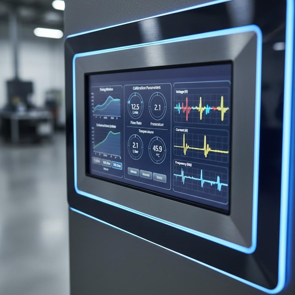
System Calibration and Parameter Configuration
Your sensors are installed and bench tested—but they're not truly protecting anything yet. Calibration transforms raw sensor signals into intelligent protection decisions. This is where many die protection system setups fall short: technicians rush through parameter configuration, accepting default settings that either trigger nuisance stops or miss genuine problems. Understanding how timing windows, sensitivity adjustments, and detection logic work together puts you in control of your system's effectiveness.
Think of calibration as teaching your system what "normal" looks like so it can recognize when something goes wrong. Let's break down exactly how to configure these critical parameters.
Setting Timing Windows and Sensitivity Parameters
Timing windows define when during each stroke cycle your system expects to see specific events. The press crankshaft rotates 360 degrees per stroke, and your protection controller uses this rotation as its timing reference. Every sensor activation must occur within its designated window—too early or too late signals a problem.
Here's how timing windows relate to stroke position: Imagine your part-out sensor should detect the ejected part when the crankshaft is between 270 and 330 degrees. If detection occurs at 250 degrees, the part ejected early—possibly a sign of improper strip position. If detection never occurs within the window, the part remained in the die. Either scenario stops the press before the next stroke causes damage.
Setting your initial timing windows requires observation during normal operation. Run the press slowly with all sensors active but protection disabled. Note exactly when each detection occurs relative to crankshaft position. Your baseline windows should bracket these normal detection times with appropriate margins—typically 10-20 degrees on each side for most applications.
Sensitivity parameters determine how strong a signal must be before the controller registers detection. Setting sensitivity too high causes missed detections when targets pass at the edge of sensing range. Setting too low triggers false detections from nearby components or electrical noise. The yield stress and yield strength of materials being processed can actually affect sensor calibration—stiffer materials tend to eject more consistently, allowing tighter sensitivity settings, while softer materials may require more tolerance.
Common calibration parameters and their effects include:
- Detection window start angle: Defines the earliest crankshaft position where detection is valid. Setting too early may capture false signals from die component movement.
- Detection window end angle: Defines the latest acceptable detection position. Setting too late may not leave sufficient stopping time before the next stroke begins.
- Sensor sensitivity/threshold: Determines the minimum signal strength registered as valid detection. Affects both false positive and false negative rates.
- Detection mode (static vs. dynamic): Static mode looks for presence/absence at a specific point. Dynamic mode detects transitions—useful when targets remain in sensing range throughout the stroke.
- Debounce time: Filters out brief signal fluctuations that could cause false triggers. Essential in electrically noisy environments.
- Stop delay: Time allowed between fault detection and press stop command. Shorter delays provide faster response but may cause unnecessary stops from transient conditions.
The relationship between yield strength and yield stress concepts applies metaphorically to calibration too—you're finding the threshold where your system responds appropriately to stress without overreacting to normal variation.
Fine-Tuning for Optimal Detection Accuracy
Initial settings rarely deliver optimal performance. Fine-tuning requires running actual production while monitoring system behavior closely. Watch for patterns: Are stops occurring at consistent crankshaft positions? Do certain sensors trigger more false alarms than others? Does detection reliability change as the die warms up during production?
Start with one die and expand systematically. This incremental implementation approach prevents overwhelming your team while building competency. Select a die that runs frequently and has known protection challenges. Configure, tune, and validate the protection scheme completely before moving to additional dies. What you learn on the first die accelerates every subsequent installation.
Temperature affects calibration more than many technicians realize. Cold dies at startup behave differently than dies that have run for hours. Materials near their yield stress of steel formability limits may behave inconsistently. Consider establishing separate parameter sets for startup conditions versus steady-state production, switching between them as the die reaches operating temperature.
When adjusting parameters, change one variable at a time and document the results. Simultaneous changes make it impossible to identify which adjustment solved—or created—a problem. This systematic approach builds institutional knowledge about your specific protection requirements.
Documenting baseline settings creates your troubleshooting foundation. For every die, record:
- Final timing window settings for each sensor
- Sensitivity values and detection modes
- Press stroke rate at which calibration was performed
- Material specifications for the calibration run
- Environmental conditions (temperature, lubricant type)
- Any known quirks or special considerations
Store this documentation where operators and maintenance technicians can access it. When problems arise weeks or months later, comparing current settings against documented baselines often reveals the issue immediately. Understanding yield strain steel behavior helps explain why material variations sometimes require calibration adjustments—different batches may yield differently even within specification.
The yield stress relationship between your detection windows and actual stroke dynamics deserves ongoing attention. As dies wear, components shift slightly, changing detection timing. Regular verification against baseline documentation catches drift before it causes problems. Schedule calibration checks after maintenance events, die sharpening, or extended downtime.
With calibration complete and documented, your protection system is nearly operational. The remaining critical step is integrating with your press controls and PLCs—ensuring your protection system can actually stop the press when it detects a problem.
System Integration with Press Controls and PLCs
Your sensors are calibrated, timing windows are set, and detection logic is configured—but none of that matters if your protection system can't communicate with your press. Integration is where die protection becomes real: the controller must receive position feedback from the press, and its stop commands must actually halt the machine before damage occurs. This critical connection point is often glossed over in setup guides, yet integration failures account for a significant portion of protection system problems.
Whether you're working with a standalone press or managing a networked multi-press environment, understanding wiring requirements, signal compatibility, and communication protocols ensures your protection investment actually delivers results.
Connecting to Press Controls and Safety Systems
Every die protection controller needs two fundamental connections to your press: a position reference signal telling it where the crankshaft is during each stroke, and an output path to stop the press when problems are detected.
Position reference signals typically come from a resolver or encoder mounted on the press crankshaft. Your protection controller uses this signal to determine timing windows and correlate sensor detections with stroke position. Older presses without built-in encoders may require retrofit installations—a worthwhile investment that enables precise, repeatable protection.
Stop signal integration must interface with your press's existing safety circuitry. Most modern installations wire the protection controller's stop output into the press control's top-stop circuit, ensuring the press halts at top dead center rather than mid-stroke. This connection must be fail-safe: if the protection controller loses power or malfunctions, the press should stop, not continue unprotected.
Consider these wiring fundamentals during installation:
- Signal voltage compatibility: Verify your protection controller's input and output voltage levels match your press control requirements—mismatched levels cause unreliable operation or equipment damage
- Cable shielding: Use shielded cables for encoder signals and route them away from high-current power conductors to prevent electrical noise interference
- Connection security: Industrial terminal blocks with proper wire gauges prevent loose connections that cause intermittent failures
- Emergency stop integration: Your protection system should tie into existing E-stop circuits, not bypass them
For facilities using automated material handling—whether miller automatic feed systems or robotic part transfer—additional integration points may be necessary. Your protection controller may need signals indicating automation status, preventing false faults when robots are cycling or feeders are indexing.
PLC Integration and Signal Configuration
Modern stamping operations increasingly connect die protection systems to facility PLCs and data collection infrastructure. This integration enables centralized monitoring, production data logging, and coordination with broader automation systems. When evaluating integration approaches for plex rockwell supplier control plans or similar quality management systems, understanding your connectivity options becomes essential.
The following table outlines common integration scenarios you'll encounter:
| Press Control Type | Connection Method | Signal Requirements | Special Considerations |
|---|---|---|---|
| Legacy Mechanical Press Controls | Discrete I/O (hardwired) | 24VDC digital inputs/outputs, relay contacts for stop commands | May require resolver retrofit for position feedback; limited data extraction capability |
| Modern Press Controls with PLC | Discrete I/O or fieldbus communication | Digital I/O plus optional Ethernet/IP, Profinet, or Modbus TCP | Fieldbus enables richer data exchange; verify protocol compatibility before purchase |
| Servo Press Systems | High-speed digital communication | Encoder signals, EtherCAT or similar real-time protocols | Tight timing requirements; protection controller must match servo system speed |
| Multi-Press Networked Environment | Ethernet-based protocols to central PLC/SCADA | TCP/IP networking, OPC-UA for data collection | Network architecture planning essential; consider bandwidth and latency requirements |
| Standalone Press (No PLC) | Direct hardwired connection | Simple relay logic for stop commands | Most straightforward installation; limited remote monitoring capability |
Communication protocol selection depends on what you need to accomplish. Simple stop/run signals require only discrete I/O connections. If you want to log fault data, track production counts, or integrate with plex rockwell supplier control plans for quality documentation, fieldbus or Ethernet protocols provide the necessary data bandwidth.
For facilities running hydroforming operations or other specialized processes alongside conventional stamping, integration complexity increases. Different press types may use incompatible protocols, requiring gateway devices or middleware to consolidate data streams.
Networked multi-press environments demand careful architecture planning. Central monitoring stations can display status from dozens of presses, but network traffic must be managed to prevent communication delays during critical stop commands. Segment protection-critical traffic from general plant networking when possible, and ensure network switches provide adequate bandwidth and reliability.
Data collection integration opens valuable possibilities: tracking stop causes over time reveals patterns that inform preventive maintenance, production planning, and even die design improvements. However, don't let data ambitions delay basic protection functionality. Get your system stopping the press reliably first, then layer on data collection capabilities incrementally.
Whether your integration is straightforward hardwiring or complex networked architecture, thorough documentation proves invaluable. Record every connection, protocol setting, and network address. When troubleshooting becomes necessary—and it will—this documentation transforms hours of detective work into minutes of verification.

Troubleshooting Common Setup and Operational Issues
Even the most carefully executed die protection system setup will eventually encounter problems. Sensors drift, connections loosen, and environmental conditions change—all factors that can degrade protection effectiveness over time. What separates well-run operations from frustrated ones isn't avoiding problems entirely; it's diagnosing and resolving them quickly when they appear.
This troubleshooting guide addresses the diagnostic gap that leaves many technicians guessing when their protection systems misbehave. Whether you're dealing with nuisance stops that kill productivity or missed detections that allow crashes, systematic diagnosis gets you back to reliable operation faster than trial-and-error approaches.
Diagnosing Common Sensor and System Issues
Most protection system problems fall into predictable categories. Understanding these patterns helps you zero in on root causes rather than chasing symptoms.
False positive scenarios—where the system stops the press without an actual problem—typically frustrate operators first. Production halts, the operator investigates, finds nothing wrong, and resets the system. Repeat this cycle enough times, and operators start ignoring or bypassing protection entirely. Common causes include:
- Sensor contamination: Lubricant buildup or metal particles on sensing faces causing detection where none should occur
- Timing window drift: Windows no longer aligned with actual part movement due to die wear or mechanical changes
- Electrical interference: Nearby variable frequency drives or welding equipment inducing spurious signals
- Loose mounting: Vibration shifting sensors into detection range of unintended targets
False negative scenarios—where actual problems go undetected—are far more dangerous. These failures allow crashes to occur despite installed protection. Causes often include:
- Sensitivity set too low: Targets passing at detection range edges fail to trigger consistently
- Detection windows too narrow: Valid detections occurring outside expected timing ranges
- Cable damage: Intermittent connections causing signal dropouts
- Sensor failure: Components reaching end of life without obvious symptoms
Materials undergoing strain hardening during forming operations can affect detection reliability in unexpected ways. As material properties change through work hardening, part ejection behavior may shift—parts exit at slightly different angles or velocities than when the die was new. This strain hardening and work hardening effect gradually moves detection events outside calibrated windows.
Environmental factors deserve particular attention during diagnosis. Temperature swings cause metal components to expand and contract, shifting sensor positions relative to targets. Humidity affects some sensor technologies more than others. Even air pressure changes in pneumatic systems can alter part ejection dynamics. When troubleshooting intermittent issues, correlate fault occurrences with environmental conditions—patterns often emerge.
Deformation hardening in processed materials creates another diagnostic consideration. Parts that have undergone significant forming may behave differently than expected during ejection, particularly when approaching material elongation limits. Monitor for changes in detection timing as dies process materials at different points in their formability range.
Error Code Interpretation and Resolution Steps
Most protection controllers generate error codes that point toward specific fault conditions. Learning to interpret these codes accelerates troubleshooting dramatically. While exact codes vary by manufacturer, common categories include:
- Timing faults: Detection occurred outside the configured window
- Missing detection: Expected sensor activation never occurred
- Continuous detection: Sensor remained active when it should have cleared
- Communication errors: Lost connection between controller and sensors or press controls
- System faults: Internal controller issues requiring service attention
The following troubleshooting matrix covers the most common symptoms, helping you move from observation to resolution efficiently:
| Symptom | Possible Causes | Diagnostic Steps | Solutions |
|---|---|---|---|
| Intermittent false stops at random positions | Electrical noise, loose connections, sensor cable damage | Check cable continuity; monitor sensor output with oscilloscope; identify nearby electrical noise sources | Repair or replace damaged cables; add shielding; relocate cables away from noise sources; install noise filters |
| Consistent false stops at specific stroke position | Sensor detecting unintended target, timing window misalignment, die component interference | Manually cycle press slowly while observing sensor output; compare current timing to baseline documentation | Adjust sensor position or angle; reconfigure timing windows; shield sensor from interfering components |
| Missed detection allowing stuck parts | Sensitivity too low, sensor out of range, target surface condition changed | Verify sensor output during manual cycling; measure actual sensing distance; inspect target surface condition | Increase sensitivity; reposition sensor closer to target; clean or refinish target surface |
| System shows continuous fault after reset | Sensor stuck in active state, foreign object in detection zone, controller malfunction | Disconnect sensors individually to isolate fault; inspect detection zones for debris; check controller diagnostics | Remove obstruction; replace failed sensor; contact manufacturer for controller service |
| Position reference errors | Encoder/resolver failure, loose coupling, signal cable damage | Verify encoder mounting security; check signal cable connections; monitor position signal quality | Tighten or replace coupling; repair cables; replace encoder if signal quality degraded |
| Communication faults between controller and press | Network issues, protocol mismatch, PLC program changes | Verify network connections and settings; confirm protocol parameters match; review recent PLC modifications | Restore network connectivity; correct protocol settings; revert PLC changes or update integration |
| Sluggish response at high stroke rates | Controller processing limitations, sensor response time inadequate, yielding load on system resources | Compare controller specifications to application requirements; measure actual response times | Upgrade to faster controller; select higher-speed sensors; reduce monitoring complexity if possible |
When to call for professional service versus handling issues in-house depends on your team's capabilities and the nature of the problem. Operator-level fixes include:
- Cleaning contaminated sensors
- Tightening loose mounting hardware
- Adjusting sensitivity within documented ranges
- Replacing cables with known spares
- Resetting after transient faults with known causes
Escalate to maintenance technicians or professional service for:
- Controller internal faults or error codes indicating hardware failure
- Repeated failures after attempted repairs
- Integration issues with press controls or PLCs
- Encoder or resolver replacement
- Firmware updates or controller reprogramming
Elongation of processed materials near forming limits can create detection challenges that look like sensor problems but actually stem from material behavior. Before replacing sensors or adjusting calibration extensively, verify that material specifications haven't changed and that parts are forming correctly.
Document every troubleshooting event, even simple ones. Patterns emerge over time—a sensor that requires monthly cleaning indicates an environmental problem worth addressing at the source. A die that consistently causes timing faults after running for two hours suggests thermal effects requiring calibration adjustment or parameter sets for different temperature conditions.
Systematic troubleshooting builds institutional knowledge that makes your entire operation more resilient. The goal isn't just fixing today's problem—it's preventing tomorrow's. With effective diagnostic procedures in place, your next priority becomes ensuring everyone on your team can execute them consistently through proper training and documentation.
Operator Training and Change Management Protocols
Here's a reality many facilities discover too late: even a perfectly configured die protection system setup fails when operators don't understand how to use it. Technology alone doesn't prevent crashes—people do. The most sophisticated sensors and controllers become expensive decorations if your team lacks the training to respond correctly when alerts trigger, or worse, if they've learned to work around protection systems that seem to create more problems than they solve.
Successful implementation requires treating training and change management with the same rigor you applied to sensor selection and calibration. Let's explore how to build the human capabilities that determine whether your protection investment delivers lasting results.
Building Operator Competency Through Structured Training
Different roles require different training depths. A press operator needs immediate response skills, while a maintenance technician needs diagnostic capabilities, and an engineer needs system-level understanding. Trying to train everyone the same way wastes time and leaves gaps in critical competencies.
Operator-level training focuses on recognition and response. Operators must understand what each alert means and exactly what actions to take. They don't need to calibrate sensors, but they absolutely need to know:
- What each indicator light and display message means
- Proper response procedures for different fault types
- When to attempt reset versus when to call for assistance
- How to perform basic visual inspections before resuming production
- Why bypassing or ignoring protection creates serious risks
Maintenance technician training builds diagnostic and repair capabilities. Similar to how a respirator welder must understand both equipment operation and safety protocols, your technicians need comprehensive knowledge covering:
- Sensor testing and replacement procedures
- Calibration verification and adjustment within documented parameters
- Cable inspection, repair, and routing best practices
- Troubleshooting using error codes and diagnostic tools
- Integration points with press controls and when to escalate issues
Engineering-level training addresses system design, optimization, and continuous improvement. Engineers should understand yield in engineering terms—not just material properties, but understanding what yield strength means for forming operations helps engineers appreciate why protection parameters must account for material variation. Training components include:
- Protection scheme design for new dies
- Performance analysis and optimization techniques
- Integration architecture with PLCs and data systems
- ROI tracking and cost-benefit evaluation methods
- Vendor coordination for upgrades and advanced troubleshooting
Hands-on practice beats classroom instruction for retention. Set up training scenarios using actual equipment whenever possible. Let operators experience fault conditions and practice responses before encountering them during production pressure. This approach mirrors how technical training programs—from community colleges to specialized institutions like tulsa welding school dallas campus—emphasize practical application alongside theoretical knowledge.
Creating Effective Documentation and Standard Procedures
Training fades without reinforcement. Documentation serves as your institutional memory, ensuring consistent practices regardless of who's on shift or how long ago initial training occurred.
Effective documentation includes:
- Quick reference guides: Laminated cards at each press showing common alerts and immediate response actions
- Standard operating procedures: Step-by-step instructions for routine tasks like startup verification and shift-change inspections
- Troubleshooting guides: Decision trees that guide technicians from symptoms to solutions
- Die-specific protection records: Baseline settings, historical issues, and special considerations for each die
- Training records: Documentation of who has been trained on what, with competency verification dates
Response protocols for system alerts must be crystal clear. When an alarm triggers at 2 AM with a skeleton crew, there's no time for interpretation. Define exactly what happens for each fault type:
- Who responds first and what they check
- What conditions allow operator reset versus requiring maintenance
- Escalation triggers and contact procedures
- Documentation requirements for each incident
- Follow-up actions to prevent recurrence
Understanding what yield strength represents—the stress point where material begins permanent deformation—provides useful context for why certain protection responses matter. Just as exceeding yield strength damages materials permanently, allowing protection faults to continue damages tooling permanently. This conceptual connection helps operators internalize why proper response matters.
Ongoing competency verification prevents skill decay. Schedule periodic refresher training, especially after extended periods without incidents. Ironically, long stretches of trouble-free operation can erode readiness—operators forget procedures they haven't needed to use. Consider:
- Quarterly reviews of response procedures with practical exercises
- Annual recertification for maintenance technicians on calibration tasks
- Post-incident debriefs that become learning opportunities for the entire team
- Skill assessments before assigning personnel to new presses or dies
Human factors ultimately determine whether your protection system succeeds long-term. If operators perceive the system as an obstacle rather than a tool, they'll find workarounds. If technicians lack confidence in their diagnostic abilities, they'll call for external service unnecessarily. If engineers don't understand the system's capabilities, they'll under-utilize available protection features.
Build buy-in by involving frontline personnel in implementation decisions where appropriate. Explain the "why" behind requirements, not just the "what." Celebrate prevented crashes rather than only tracking stops as productivity losses. When your team understands that proper protection operation directly impacts their safety and job security, compliance becomes cultural rather than coerced.
With trained personnel and documented procedures in place, you've built the foundation for sustainable protection. The final piece—measuring results and continuously improving—transforms your die protection system from an installed feature into a competitive advantage.
Post-Installation Optimization and ROI Measurement
You've installed sensors, calibrated parameters, integrated with press controls, and trained your team. But here's what separates good die protection system setups from great ones: the optimization phase that most facilities skip entirely. Installation isn't the finish line—it's the starting point for continuous improvement that compounds value over time.
Think about it this way: your initial setup represents your best guess at optimal protection based on available information. Actual production reveals what you couldn't predict. Verification testing confirms your system performs as intended, while ongoing measurement ensures it continues delivering value as conditions evolve.
Verification Testing and Performance Validation
Before declaring your installation complete, systematic verification testing confirms every protection point functions correctly under real production conditions. This validation phase catches setup errors that bench testing missed and establishes the performance baseline you'll reference for years to come.
Structured verification testing should cover three critical areas:
- Detection reliability testing: Run extended production cycles while monitoring every sensor activation. Verify detections occur consistently within timing windows across hundreds of strokes, not just the handful checked during bench testing.
- Fault response testing: Deliberately create controlled fault conditions—short feeds, simulated stuck parts, blocked ejection paths—and confirm the system stops the press before damage would occur. This controlled testing builds confidence that protection works when it matters.
- Integration verification: Confirm stop commands reach the press control reliably, data logging captures all events accurately, and communication with PLCs or monitoring systems functions as designed.
Document everything during verification. Record actual detection timing, response speeds, and any anomalies observed. This documentation becomes your performance baseline—the reference point for evaluating system health months and years later.
Understanding material properties enhances verification effectiveness. The relationship between yield strength vs tensile strength affects how parts behave during forming and ejection. Parts formed near their tensile limits may exit differently than those processed more conservatively, and your verification testing should include material variations you'll encounter in production.
Baseline establishment captures system performance metrics when everything works correctly. Key baseline measurements include:
- Detection timing distributions for each sensor
- False stop rates during normal operation
- Response times from fault detection to press stop
- Environmental conditions during baseline testing
The steel modulus of elasticity—approximately 200 GPa for most steels—affects how tooling deflects under load. This modulus of steel influences sensor positioning requirements and detection timing as dies flex during operation. Quality tooling manufactured to precise specifications minimizes these variations, making protection calibration more straightforward and reliable.
This is where precision stamping die solutions with advanced CAE simulation capabilities prove their value. IATF 16949-certified manufacturers like Shaoyi use simulation to optimize die designs before cutting steel, reducing the dimensional variations and forming inconsistencies that complicate protection system setup. When tooling performs predictably, protection calibration becomes more precise and stable over time.
Measuring ROI and Continuous Improvement
Here's the gap most competitors ignore completely: quantifying the return on your protection investment. Without measurement, you can't demonstrate value to management, justify upgrades, or identify improvement opportunities. Effective ROI tracking transforms die protection from a cost center into a documented profit driver.
Track these key performance indicators to quantify protection value:
- Crash prevention events: Every time your system stops the press before a crash, document the incident. Estimate repair costs avoided based on similar historical crashes or industry benchmarks.
- Downtime reduction: Compare unplanned downtime before and after protection implementation. Include not just repair time but production scheduling disruptions, expedited shipping for replacement parts, and overtime costs.
- Tooling lifespan extension: Monitor die maintenance intervals and replacement frequency. Protected dies typically last significantly longer than unprotected ones.
- Quality improvements: Track defect rates for parts produced on protected presses. Detection of problems before they cause crashes often catches quality issues earlier in the process.
- False stop rates: Monitor nuisance stops that halt production without preventing actual problems. High false stop rates indicate optimization opportunities.
Understanding modulus of elasticity of steel helps explain why quality tooling matters for consistent protection. Young's modulus of steel determines how much tooling deflects under forming loads. Dies with inconsistent material properties or poor manufacturing tolerances deflect unpredictably, making sensor calibration challenging and increasing false detection rates.
Cost-benefit analysis frameworks help justify protection investments and prioritize improvements. Consider this approach:
| Cost Category | What to Measure | Typical Calculation Method |
|---|---|---|
| Direct crash costs avoided | Tooling repair/replacement, press repair, scrapped materials | Historical crash cost average × prevention events |
| Downtime costs avoided | Lost production value during unplanned stops | Hourly production value × downtime hours prevented |
| Quality cost reduction | Scrap reduction, rework elimination, customer claim reduction | Defect rate reduction × cost per defect |
| Tooling longevity savings | Extended die life, reduced sharpening frequency | Baseline maintenance costs − current maintenance costs |
| System operating costs | Maintenance labor, replacement sensors, calibration time | Actual costs tracked over measurement period |
Most facilities find protection ROI ranges from 300% to over 1000% annually when all factors are considered. The key is actually tracking the data rather than assuming value exists.
Continuous improvement compounds your protection investment over time. Establish regular review cycles—monthly for operational metrics, quarterly for deeper analysis. Look for patterns:
- Which dies cause the most protection events? They may need design improvements or additional sensors.
- Are false stop rates increasing over time? Sensors may need cleaning or recalibration.
- Do certain shifts or operators experience more issues? Additional training may be needed.
- How do protection events correlate with material batches? Incoming material variation may require attention.
The elastic modulus of your tooling materials affects long-term protection stability. Higher-quality tool steels maintain dimensional stability better over extended production runs, reducing calibration drift and false detection issues. When specifying new dies, consider how material selection impacts protection system maintenance requirements.
Remember that your die protection system setup evolves with your operation. New dies require new protection schemes. Process improvements may shift detection requirements. Material specification changes affect forming behavior. Build regular protection system reviews into your continuous improvement culture.
Quality tooling forms the foundation of effective die protection. When dies perform predictably and consistently, protection systems calibrate more precisely and maintain accuracy longer. The relationship between tensile strength vs yield strength in forming operations affects how parts exit the die—and therefore how reliably sensors detect them. Investing in precision tooling from qualified manufacturers reduces protection complexity and improves long-term results.
With verification complete, ROI tracking in place, and continuous improvement processes established, your die protection implementation delivers compounding value. What started as crash prevention becomes a competitive advantage—lower costs, higher quality, and more predictable production that sets your operation apart.
Frequently Asked Questions About Die Protection System Setup
1. What are the five steps to starting a die protection program?
The five essential steps include: selecting a compatible control system that matches your press specifications, developing a comprehensive sensor connection scheme based on die complexity, setting up a sensor lab for bench testing before production, establishing application guidelines with documented calibration parameters, and developing training programs for operators and maintenance staff. Each step builds upon the previous one—rushing through any phase typically results in unreliable protection or excessive false stops that undermine operator confidence.
2. How do die protection systems prevent damage to tooling and presses?
Die protection systems use strategically placed sensors to monitor critical events during each press stroke cycle. These sensors detect whether parts have ejected properly, materials have fed correctly, and die components are positioned correctly. When abnormalities occur—such as a stuck part, short feed, or slug buildup—the system sends a stop command to halt the press before the next stroke causes damage. Modern systems correlate sensor signals with crankshaft position, enabling precise timing-based detection that human observation cannot match at production speeds.
3. What types of sensors are used in die protection systems?
Common sensor types include inductive proximity sensors for ferrous metal detection with 1-30mm range, photoelectric sensors for non-ferrous materials like aluminum, fiber optic sensors for tight spaces and extreme temperatures, touch sensors for positive part confirmation with heavy gauge materials, and capacitive sensors for non-metallic materials. Selection depends on your specific application—material type, detection distance requirements, environmental conditions, and response time needs at your operating stroke rates.
4. How do I set up timing windows for die protection?
Timing windows define when during each 360-degree stroke cycle your system expects specific detection events. Start by running the press slowly with sensors active but protection disabled, noting exactly when each detection occurs relative to crankshaft position. Set initial windows to bracket these normal detection times with 10-20 degree margins on each side. Fine-tune through production monitoring, adjusting for factors like die temperature changes, material variations, and stroke rate differences. Document baseline settings for each die to enable quick troubleshooting when issues arise.
5. What causes false stops in die protection systems and how can I fix them?
False stops typically result from sensor contamination from lubricants or metal particles, timing window drift due to die wear, electrical interference from nearby equipment, or loose sensor mounting from vibration. Diagnose by checking cable continuity, monitoring sensor output with oscilloscope, and comparing current timing to documented baselines. Solutions include regular sensor cleaning schedules, recalibrating timing windows after die maintenance, adding cable shielding, and using thread-locking compound on mounting hardware. Precision tooling from IATF 16949-certified manufacturers like Shaoyi reduces false stops by ensuring consistent die performance.