 Small batches, high standards. Our rapid prototyping service makes validation faster and easier —

Welding Repair For Tool Steel: Stop Cracking Dies And Losing Money
Understanding Welding Repair for Tool Steel Fundamentals
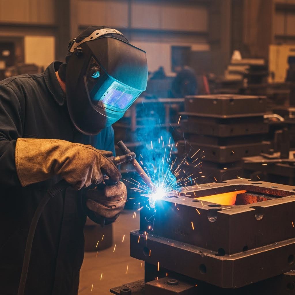
Have you ever watched a perfectly good die crack during production, knowing that a single repair mistake caused weeks of downtime and thousands in losses? Welding repair for tool steel isn't just another welding job—it's a specialized discipline that separates skilled craftspeople from those who inadvertently destroy expensive tooling.
Unlike welding mild steel or structural components, welding tool steel demands an entirely different approach. The materials you're working with contain high carbon content (typically 0.5% to 1.5% or higher), complex alloying elements like chromium, molybdenum, and vanadium, and exhibit extreme sensitivity to thermal changes. These characteristics make every repair a precision operation where small mistakes lead to catastrophic failures.
Why Tool Steel Demands Specialized Welding Expertise
When you're welding hardened steel used in dies and tooling, you're dealing with materials specifically engineered to resist deformation, wear, and heat. These same properties that make tool steel invaluable in manufacturing also make it incredibly challenging to weld successfully.
Consider what happens during a typical weld: you're introducing intense localized heat into a material designed to maintain specific hardness characteristics. The heat-affected zone (HAZ) experiences rapid temperature changes that can transform the carefully controlled microstructure into something brittle and crack-prone. Every tool and die maker understands this fundamental challenge—the very properties that make tool steel exceptional also make it unforgiving during repair.
The alloying elements present additional complications. Chromium increases hardenability but also sensitivity to thermal shock. Vanadium and tungsten contribute to wear resistance but require precise temperature control during welding. Understanding yield in engineering terms helps explain why these materials behave so differently—their stress-strain relationships under thermal cycling differ dramatically from ordinary steels.
The Metallurgical Challenge Behind Every Repair
Successful tool and die repair requires understanding three interconnected metallurgical realities:
- Carbon migration: High carbon content means greater hardening potential during cooling, increasing crack susceptibility
- Alloy sensitivity: Each alloying element responds differently to heat, requiring tailored approaches for each steel grade
- Thermal stress accumulation: Uneven heating and cooling creates internal stresses that manifest as cracks hours or days after welding
This guide serves as your comprehensive reference for navigating these challenges—bridging the gap between manufacturer specifications and real-world repair scenarios. Whether you're addressing edge chips, surface wear, or through-cracks, the principles covered here apply across the full spectrum of tool steel repair situations.
A properly executed tool steel repair costs a fraction of replacement while restoring 90-100% of original performance. However, an improper repair doesn't just fail—it often damages the component beyond any future repair possibility, turning a recoverable situation into total loss.
The economic stakes are significant. Production dies can represent investments of tens of thousands of dollars, and their failure during production runs creates cascading costs in downtime, delayed shipments, and emergency replacements. Understanding yield in engineering applications helps appreciate why these repairs matter—properly restored tooling continues performing within its designed stress parameters, while poorly repaired pieces fail unpredictably under normal operating loads.
Throughout this guide, you'll learn the systematic approach that professional welders use when welding tool steel: from proper identification and preparation through process selection, filler matching, and post-weld heat treatment. Each step builds on the previous, creating a reliable framework for successful repairs.
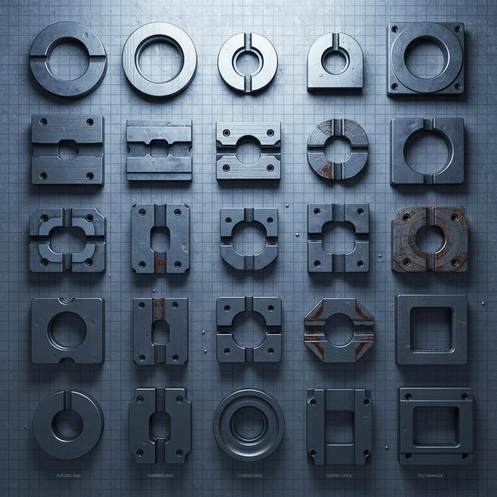
Tool Steel Categories and Their Welding Characteristics
Before striking an arc on any tool steel component, you need to answer one critical question: what steel grade am I working with? Different steel grades respond dramatically differently to welding heat input, and misidentifying your material almost guarantees failure. Understanding these categories transforms guesswork into systematic, repeatable success.
Tool steels fall into distinct families, each engineered for specific applications. Their chemical compositions determine not just performance characteristics but also how they behave during steel and welding operations. Let's break down what you need to know about each category.
Hot Work vs Cold Work Steel Repair Considerations
Hot work steels (H-series) are designed to maintain hardness at elevated temperatures—think die casting dies, forging dies, and extrusion tooling. These grades contain moderate carbon (0.35-0.45%) with chromium, tungsten, or molybdenum additions. Their relatively lower carbon content makes them the most weldable tool steel category, though "weldable" here is relative to other tool steels, not mild steel.
Cold work steels present significantly greater challenges. Grades like D2, A2, and O1 contain higher carbon levels (0.90-1.50%) to achieve extreme hardness at room temperature. This elevated carbon content directly impacts the yield stress of steel in the heat-affected zone, creating harder, more brittle microstructures during cooling. The yield point for steel in these grades shifts dramatically based on thermal history, making temperature control absolutely critical.
High-speed steels (M-series and T-series) represent the most challenging category for welding repair. With carbon content often exceeding 0.80% plus substantial tungsten, molybdenum, and vanadium additions, these materials require extremely careful thermal management. Many professionals recommend against field welding high-speed steels entirely, preferring specialized shop conditions.
Shock-resistant steels (S-series) fall between hot work and cold work grades in weldability. Their moderate carbon content (0.50-0.60%) combined with silicon and manganese additions allows for reasonable weldability when proper procedures are followed.
Identifying Your Tool Steel Grade Before Welding
Sounds complex? Here's your practical starting point. Always attempt to identify the exact grade through documentation, stamping marks, or manufacturer records before beginning any repair. When documentation isn't available, spark testing provides useful clues—high-carbon steels produce bushy, explosive spark patterns while lower-carbon grades show simpler, less explosive streams.
The Powder Metallurgy D2 Tool Steel (e.g., DC53 or equivalent) exemplifies why precise identification matters. Powder metallurgy D2 exhibits more uniform carbide distribution than conventional D2, potentially requiring adjusted welding parameters despite the same nominal composition. Treating all D2 identically ignores real metallurgical differences that affect repair outcomes.
| Tool Steel Category | Common Grades | Typical Applications | Carbon Content Range | Weldability Rating |
|---|---|---|---|---|
| Hot Work (H-Series) | H11, H13, H21 | Die casting, forging dies, extrusion tooling | 0.35-0.45% | Fair to Good |
| Cold Work (Air-Hardening) | A2, A6 | Blanking dies, forming dies, gauges | 0.70-1.00% | Poor to Fair |
| Cold Work (High-Carbon/Chromium) | D2, D3, D7 | Long-run dies, slitters, wear-resistant tooling | 1.40-1.60% (for D2) | Poor |
| Cold Work (Oil-Hardening) | O1, O2, O6 | Taps, reamers, general tooling | 0.90-1.45% | Poor |
| Shock-Resistant (S-Series) | S1, S5, S7 | Chisels, punches, shear blades | 0.45-0.65% | Fair |
| High-Speed (M/T-Series) | M2, M42, T1 | Cutting tools, drills, end mills | 0.80-1.30% | Very Poor |
Notice how the yield strength of steel varies across these categories based on heat treatment condition. A properly hardened D2 die operates at significantly different stress levels than the same material in its annealed state. Your welding procedure must account for not just the grade but also its current heat treatment condition.
When you cannot definitively identify the steel grade, treat the material as belonging to the most challenging category its appearance and application suggest. Overestimating difficulty adds time and cost but preserves the component. Underestimating leads to cracked repairs and scrapped tooling. With identification established, you're ready to address the next critical phase: proper pre-weld preparation and preheat requirements.
Pre-Weld Preparation and Preheat Requirements
Can you weld hardened steel successfully without proper preparation? Technically yes—but you'll almost certainly regret it. The difference between a repair that lasts years and one that cracks within hours often comes down to what happens before the arc ever touches metal. Proper pre-weld preparation isn't optional when working with tool steel; it's the foundation that determines success or failure.
Think of preparation as insurance. Every minute invested in cleaning, inspection, and preheat pays dividends in reduced rework, eliminated cracking, and restored tooling that performs reliably. Let's walk through the essential steps that separate professional-grade repairs from costly failures.
Essential Cleaning and Crack Identification
Start every repair with thorough cleaning. Tool steel components accumulate oils, lubricants, scale, and contaminants during service that create welding defects if left in place. Your cleaning protocol should include:
- Solvent degreasing: Remove all oils and lubricants using acetone or appropriate industrial solvents
- Mechanical cleaning: Grind or wire brush the repair area to bright metal, extending at least 1 inch beyond the planned weld zone
- Oxide removal: Eliminate any rust, scale, or heat discoloration that could introduce contamination
- Final wipe: Use clean, lint-free cloths with solvent immediately before welding
Crack identification requires careful inspection—and often reveals more damage than initially visible. Surface cracks frequently extend deeper than they appear. Use dye penetrant testing on critical components to map crack extent before grinding. When preparing cracks for welding, grind completely through the crack depth plus an additional 1/16 inch into sound material. Leaving any crack remnant guarantees the defect will propagate through your new weld.
Consider stress relief requirements before welding. Components that have been in service accumulate residual stresses from repeated loading cycles. For heavily stressed tooling or pieces showing multiple crack indications, a pre-weld stress relief heat treatment can prevent crack propagation during welding. This step adds time but often saves the entire repair from failure.
Preheat Temperature Selection by Steel Grade
Preheat represents the single most critical variable in tool steel welding success. Proper welding temperatures slow cooling rates in the heat-affected zone, reducing hardness gradients and thermal stresses that cause cracking. Skip or shortcut this step, and you're essentially gambling with your repair.
Why does preheat matter so much? When you weld steel for welding applications involving high carbon content, rapid cooling transforms the microstructure into extremely hard, brittle martensite. This transformation creates internal stresses that exceed the material's strength, resulting in cracks. Adequate preheat slows cooling enough to form softer, more ductile microstructures or at least reduces the severity of martensitic transformation.
| Tool Steel Family | Preheat Temperature Range | Interpass Maximum | Special Considerations |
|---|---|---|---|
| Hot Work (H-Series) | 400-600°F (205-315°C) | 700°F (370°C) | Lower range for thin sections; higher for heavy components |
| Cold Work Air-Hardening (A-Series) | 400-500°F (205-260°C) | 550°F (290°C) | Uniform heating essential; avoid localized hot spots |
| Cold Work High-Carbon (D-Series) | 700-900°F (370-480°C) | 950°F (510°C) | Highest preheat requirements; consider furnace heating |
| Oil-Hardening (O-Series) | 350-500°F (175-260°C) | 550°F (290°C) | Moderate preheat; maintain throughout repair |
| Shock-Resistant (S-Series) | 300-500°F (150-260°C) | 600°F (315°C) | More forgiving than cold work grades |
| High-Speed (M/T-Series) | 900-1050°F (480-565°C) | 1100°F (595°C) | Furnace preheat strongly recommended; expert-level repairs |
Achieving proper preheat requires appropriate equipment. For smaller components, oxy-fuel torches work adequately when heat is applied uniformly and verified with temperature-indicating crayons or infrared pyrometers. Larger dies benefit from furnace preheating, which ensures uniform temperature throughout the mass. Never rely on surface temperature alone—heavy sections require soak time for heat to penetrate completely.
The best steel for welding in tool steel repair scenarios isn't necessarily the easiest grade but rather the one properly prepared. Even challenging D2 becomes manageable with adequate preheat, while "easier" grades fail when preheated insufficiently.
Preventing Hydrogen-Induced Cracking in Tool Steel
Hydrogen embrittlement represents one of the most insidious failure modes in tool steel welding—and one that competitors consistently overlook. Unlike hot cracks that appear during or immediately after welding, hydrogen-induced cracks can develop hours or even days later, often after the component has returned to service.
Here's what happens: hydrogen dissolves into the molten weld pool during welding, sourced from moisture, contaminated consumables, or atmospheric humidity. As the weld cools, hydrogen becomes trapped in the solidifying metal. Over time, hydrogen atoms migrate toward high-stress areas, accumulating until they create internal pressure sufficient to initiate cracks. The high hardness of tool steel weld zones makes them especially vulnerable—hard microstructures have lower hydrogen tolerance than softer materials.
Preventing hydrogen-induced cracking requires systematic attention to multiple factors:
- Low-hydrogen electrodes: Always use EXX18 or similar low-hydrogen classifications for stick welding; these electrodes contain minimal moisture-producing compounds in their coatings
- Proper electrode storage: Store low-hydrogen electrodes in heated rod ovens at 250-300°F (120-150°C); once removed, use within 4 hours or re-bake per manufacturer specifications
- Filler metal conditioning: Bake electrodes that have been exposed to atmospheric moisture for 1-2 hours at 500-700°F (260-370°C) before use
- Controlled interpass temperatures: Maintain minimum interpass temperatures matching preheat levels to prevent rapid cooling between passes
- Post-weld hydrogen bakeout: For critical repairs, holding the component at 400-450°F (205-230°C) for 1-2 hours after welding allows hydrogen to diffuse out before cracking occurs
Environmental controls matter significantly. Your welding bay setup should minimize moisture exposure—avoid welding when humidity exceeds 60% without supplemental measures. Keep consumables sealed until use, and never weld with electrodes that show any signs of coating damage or moisture absorption.
A respirator welder working in proper conditions maintains both personal safety and weld quality. Adequate ventilation removes welding fumes while controlling atmospheric moisture around the work zone. The respirator welder also avoids introducing moisture from breath into the immediate welding environment during close-proximity work on precision repairs.
Consider these additional environmental factors for your welding area:
- Maintain ambient temperature above 50°F (10°C) minimum
- Use dehumidification in humid climates or seasons
- Store base materials in climate-controlled conditions before welding
- Preheat fixtures and backing materials to prevent condensation on hot workpieces
The investment in hydrogen control pays off in eliminated callbacks and repairs that perform reliably for their full expected service life. With proper preparation, preheat, and hydrogen prevention measures in place, you're positioned to select the optimal welding process for your specific repair scenario.
Welding Process Selection for Tool Steel Repair
Which welding process should you use for your tool steel repair? The answer depends on factors that most guides address in isolation—but real-world success requires understanding how these processes compare against each other for specific repair scenarios. Choosing the wrong process doesn't just affect weld quality; it can introduce excessive heat, cause distortion, or make precision work nearly impossible.
Three primary processes dominate tool steel repair work: Shielded Metal Arc Welding (SMAW/stick), Gas Tungsten Arc Welding (GTAW/TIG), and Gas Metal Arc Welding (GMAW/MIG). Each brings distinct advantages and limitations that make process selection a critical decision point in your repair strategy.
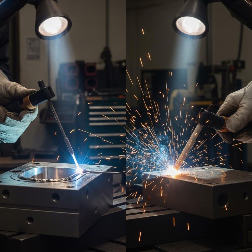
TIG Welding for Precision Tool Steel Repairs
Gas tungsten arc welding stands as the preferred method for most precision tool steel repairs—and for good reason. The process delivers unmatched control over heat input, allowing welders to work on crack repairs and fine detail areas without the thermal damage that other processes might cause.
What makes TIG exceptional for this application? You're controlling the welding tool with one hand while feeding filler metal with the other, giving you complete authority over deposition rate and heat input. This independent control proves invaluable when working on hardened components where excessive heat destroys carefully developed microstructures.
Modern micro-TIG technology has expanded what's possible in tool steel repair. These specialized systems operate at extremely low amperages (sometimes below 5 amps), enabling repairs on features that were previously considered too delicate for welding. Micro-TIG excels at:
- Sharp edge restoration: Rebuilding cutting edges without rounding or heat distortion
- Precision cavity repair: Addressing wear in intricate die details
- Crack repair in thin sections: Welding without burn-through or excessive HAZ development
- Dimensional restoration: Adding material with minimal post-weld machining required
When reviewing engineering drawings for die repairs, you'll encounter various specifications indicating weld requirements. A weld symbol on the drawing communicates joint design, weld size, and process requirements. Understanding these symbols—including the fillet weld symbol for corner and lap joints—helps ensure your repair matches design intent.
When to Choose Stick vs TIG for Die Repair
Stick welding remains relevant for tool steel repair despite TIG's precision advantages. SMAW offers faster deposition rates for surface buildup, works well in less-than-ideal conditions, and requires less operator dexterity for straightforward repairs. When you need to rebuild significant material on wear surfaces or repair large edge damage, stick welding often proves more practical than TIG.
However, stick welding introduces more heat per unit of deposited metal and provides less precise control. The slag covering requires removal between passes, and the process doesn't work well for intricate geometries. For groove weld applications requiring deep penetration on thicker sections, stick welding can be appropriate—but precision suffers compared to TIG.
MIG welding, including specialized high-alloy MIG welding techniques, sees limited use in tool steel repair. While MIG offers excellent deposition rates and works well for production welding, the higher heat input and reduced control make it problematic for hardened tool steel. Spot welder welding applications occasionally appear in tooling work, but primarily for fixture and holder fabrication rather than die repair itself.
| Criteria | TIG/GTAW | Stick/SMAW | MIG/GMAW |
|---|---|---|---|
| Precision Level | Excellent—best for detail work | Moderate—suitable for general repairs | Lower—better for production than repair |
| Heat Input Control | Superior—independent amperage and filler control | Moderate—electrode diameter limits adjustment | Fair—wire feed rate links to heat input |
| Filler Metal Options | Wide range—any compatible wire or rod | Limited to available electrode types | Limited to spooled wire availability |
| Best Repair Scenarios | Crack repair, edge restoration, precision buildup | Surface buildup, large edge repairs, field work | Rarely preferred for tool steel repair |
| Skill Requirement | High—requires significant practice | Moderate—more forgiving technique | Lower—but less applicable to this work |
| Equipment Portability | Moderate—requires shielding gas supply | Excellent—minimal setup required | Lower—gas and wire feed system needed |
Process selection ultimately depends on your specific repair type. Consider these guidelines:
- Edge repair: TIG for precision edges requiring minimal grinding; stick for heavily damaged edges needing significant buildup
- Surface buildup: Stick for large areas; TIG for precision surfaces where finish matters
- Crack repair: TIG almost exclusively—the control prevents crack re-initiation from thermal stress
- Dimensional restoration: TIG for tight tolerances; stick acceptable when substantial machining follows
Remember that process selection interacts with your earlier preparation decisions. A component preheated to 800°F for D2 repair works well with either TIG or stick, but the post-weld cooling control requirements remain unchanged regardless of process. Your welding tool choice affects execution, but metallurgical fundamentals still govern success.
With your welding process selected based on repair requirements, the next critical decision involves matching filler metals to your specific tool steel grade—a choice that directly impacts repair durability and performance.
Filler Metal Selection and Electrode Matching
You've prepared the component properly, selected your welding process, and achieved ideal preheat temperatures. Now comes a decision that can make or break your entire repair: which filler metal matches your tool steel grade? Improper filler selection ranks among the most common causes of tool steel repair failure—yet systematic guidance on this topic remains surprisingly scarce.
Filler metal selection for tool welding goes far beyond grabbing whatever electrode happens to be on the shelf. The chemistry of your filler metal interacts with the base material to determine final weld properties, crack susceptibility, and long-term performance. Let's build a systematic framework for matching fillers to tool steels.
Matching Filler Metals to Tool Steel Grades
The fundamental principle sounds simple: match filler composition to base metal composition. In practice, this requires understanding several competing factors that influence your choice.
When working with welded steel in tool applications, you're balancing hardness requirements against crack susceptibility. A filler that matches base metal hardness provides optimal wear resistance but increases cracking risk. A softer filler reduces cracking tendency but may wear faster in service. Your decision depends on the repair location and service conditions.
Consider these filler metal categories and their applications:
- Matching composition fillers: Used when the weld must achieve base metal hardness after heat treatment; essential for cutting edges and high-wear surfaces
- Undermatching (softer) fillers: Provide stress relief at the weld interface; ideal for structural repairs, non-wear areas, and crack-sensitive applications
- Nickel-based fillers: Offer excellent compatibility with high-alloy tool steels; provide cushioning effect that absorbs thermal stresses
- Cobalt-based fillers: Deliver exceptional hot hardness for hot work die repairs; maintain properties at elevated service temperatures
- Stainless steel fillers: Sometimes used for corrosion-resistant overlays or when joining dissimilar materials
For welder steel applications involving H-series hot work grades, fillers matching H11 or H13 composition work well when post-weld heat treatment will follow. These fillers contain similar chromium, molybdenum, and vanadium levels that respond appropriately to tempering cycles.
Cold work steels like D2 present greater challenges. A tool steel welding rod matching D2 composition achieves excellent hardness but requires extremely careful heat control. Many experienced welders prefer slightly undermatching fillers—perhaps an H13-type—for D2 repairs in non-critical wear zones, accepting some hardness reduction in exchange for dramatically improved crack resistance.
Specialty Electrodes for High-Carbon Repairs
High-carbon tool steels demand specialty electrodes designed specifically for challenging metallurgical conditions. Standard mild steel electrodes simply cannot perform in these applications—they dilute with high-carbon base metal, creating brittle, crack-prone deposits.
When selecting a tool steel welding rod for high-carbon applications, prioritize these criteria:
- Low-hydrogen designation: Essential for preventing hydrogen-induced cracking; look for EXX18 classifications in stick electrodes or properly stored TIG filler rods
- Appropriate alloy content: Filler should contain sufficient chromium and molybdenum to develop adequate hardness after heat treatment
- Controlled carbon levels: Some specialty fillers deliberately limit carbon to reduce cracking while maintaining reasonable hardness
- Pre-alloyed carbide formers: Vanadium and tungsten in the filler help develop wear-resistant carbides in the final deposit
Nickel-bearing fillers deserve special attention for crack-prone repairs. Adding 2-5% nickel to the filler composition improves toughness and reduces crack sensitivity without dramatically affecting hardness. Some manufacturers offer tool steel-specific electrodes with optimized nickel additions for exactly this purpose.
What happens when you choose incorrectly? Improper filler selection leads to several failure modes that often don't appear until the component returns to service:
- HAZ brittleness: Mismatched filler chemistry can create unfavorable phases in the heat-affected zone that crack under operational stress
- Interface weakness: Incompatible fillers may not properly fuse with the base metal, creating disbonding under load
- Premature wear: Understrength fillers wear rapidly, requiring repeat repairs or causing dimensional problems
- Delayed cracking: High-carbon dilution from base metal into unsuitable filler creates crack-susceptible deposits that fail days or weeks later
For critical repairs where failure consequences are severe, consider consulting filler metal manufacturers directly. Most major manufacturers maintain technical support teams who can recommend specific products for your exact base metal and application. This consultation adds minimal time while dramatically improving repair success probability.
With filler metal selection complete, you're equipped to execute your repair—but even perfect technique can't prevent every defect. Understanding how to diagnose and prevent common welding defects in tool steel ensures your repairs perform reliably in demanding production environments.

Troubleshooting Common Welding Defects in Tool Steel
Even when you've followed every preparation step correctly, defects can still appear in tool steel weld repairs. The difference between experienced welders and novices isn't avoiding problems entirely—it's recognizing defects quickly, understanding their root causes, and knowing whether to accept, repair, or start over. This troubleshooting guide addresses the systematic diagnosis and prevention approaches that keep your repairs performing reliably.
Tool steel's unforgiving nature means small defects that might be acceptable in structural welding become serious failure points under the stresses of die and tooling applications. Understanding the relationship between material behavior and defect formation helps you prevent problems before they occur.
Diagnosing Cracks in Tool Steel Weld Repairs
Cracking represents the most common and most serious defect category in tool steel welding. These cracks fall into two primary classifications based on when they form—and each type demands different prevention strategies.
Hot cracking occurs during solidification while the weld metal is still at elevated temperatures. You'll typically notice these cracks immediately or shortly after welding completes. They appear as centerline cracks running along the weld bead or as crater cracks at weld termination points. Hot cracks form when shrinkage stresses exceed the strength of partially solidified metal.
Cold cracking develops after the weld has cooled—sometimes hours or even days later. These hydrogen-induced cracks typically appear in the heat-affected zone rather than the weld metal itself. Cold cracks often remain invisible during immediate post-weld inspection, making them particularly dangerous. The material reaches its yield point under internal hydrogen pressure combined with residual stresses, initiating fracture.
When inspecting for cracks, look for these indicators:
- Visual surface cracks: Obvious linear discontinuities visible without magnification
- Crater cracks: Star-shaped or linear cracks at weld stops
- Toe cracks: Cracks initiating at the junction between weld and base metal
- Underbead cracks: Cracks in the HAZ running parallel to and beneath the weld bead
- Delayed appearance: New cracks appearing 24-48 hours after welding indicates hydrogen-induced cracking
Understanding yield stress and yield strength relationships helps explain why tool steels crack so readily. High-hardness materials have elevated yield strength but reduced ductility—they resist deformation up to a point, then fracture suddenly rather than deforming plastically. This behavior makes stress management through preheat and controlled cooling absolutely essential.
Preventing Heat-Affected Zone Brittleness
The heat-affected zone presents unique challenges in tool steel repair. This region experiences temperatures high enough to alter the base metal's microstructure but doesn't melt and resolidify like the weld metal. The result? A zone with properties different from both the original base metal and the weld deposit.
HAZ brittleness develops through several mechanisms. Rapid heating followed by rapid cooling transforms the carefully controlled base metal microstructure into untempered martensite—extremely hard but dangerously brittle. Additionally, strain hardening and work hardening effects accumulate as the material experiences thermal cycling stresses.
What exactly happens during this process? When metal undergoes plastic deformation, dislocations multiply within the crystal structure. This deformation hardening increases strength but decreases ductility. In the HAZ, thermal stresses create localized plastic deformation even without external loading. The interaction between strain hardening and work hardening effects from thermal cycling compounds with transformation hardening from phase changes, creating zones of extreme brittleness.
Preventing HAZ brittleness requires controlling cooling rates and managing thermal gradients:
- Maintain adequate preheat: Slows cooling to prevent hard martensite formation
- Control interpass temperature: Prevents cumulative thermal shock from multiple passes
- Use appropriate heat input: Balance penetration needs against excessive HAZ development
- Plan post-weld heat treatment: Tempering cycles reduce HAZ hardness to acceptable levels
| Defect Type | Primary Causes | Prevention Methods | Repair Solutions |
|---|---|---|---|
| Hot Cracking (Centerline) | High sulfur/phosphorus content; excessive depth-to-width ratio; rapid cooling | Use low-impurity filler metals; adjust bead shape; reduce travel speed | Grind out completely; reweld with modified parameters |
| Hot Cracking (Crater) | Abrupt arc termination; shrinkage in final weld pool | Taper current at stops; backfill craters; avoid stopping on edges | Grind crater; restart with proper technique |
| Cold Cracking (Hydrogen-Induced) | Hydrogen absorption; high residual stress; susceptible microstructure | Low-hydrogen consumables; proper preheat; post-weld bakeout | Complete removal required; re-prep and reweld |
| Underbead Cracking | Hydrogen diffusion into HAZ; high hardness; restraint stress | Higher preheat; hydrogen control; reduce restraint | Grind below crack depth; preheat and reweld |
| HAZ Brittleness | Rapid cooling; inadequate preheat; no PWHT | Proper preheat; controlled cooling; post-weld tempering | PWHT may salvage; severe cases require complete re-repair |
| Porosity | Contamination; moisture; inadequate shielding; excessive travel speed | Thorough cleaning; dry consumables; proper gas coverage | Minor porosity may be acceptable; severe requires grinding and rewelding |
| Distortion | Excessive heat input; improper welding sequence; inadequate fixturing | Minimize heat input; balanced weld sequence; proper restraint | Straightening with heat; stress relief; machining compensation |
Visual Inspection Criteria and Acceptance Decisions
Not every imperfection requires complete re-work. Understanding when to accept, repair, or reject welds saves time while maintaining quality standards. Your inspection should follow a systematic approach:
Immediate post-weld inspection: Examine the weld while still warm (but safe to approach) for hot cracks and obvious defects. Check crater areas, weld toes, and any visible porosity. Document findings before the component cools completely.
Delayed inspection: Re-examine the repair after 24-48 hours, particularly for cold work and high-carbon grades susceptible to delayed hydrogen cracking. Any new indications appearing after initial inspection suggest hydrogen-related problems requiring complete removal and re-repair with improved hydrogen control.
Acceptance criteria depend on repair location and service conditions:
- Critical wear surfaces: Zero tolerance for cracks; minimal porosity acceptable if small and isolated
- Structural areas: Small isolated pores may be acceptable; no cracks permitted
- Non-critical zones: Minor imperfections acceptable if they won't propagate under service loads
- Dimensional accuracy: Sufficient material for machining to final dimensions required
When defects require repair, resist the temptation to simply weld over existing problems. The strain hardening and work hardening that occurred during the initial attempt remains in the material. Grinding completely through defective areas removes both the visible defect and the affected microstructure. For hydrogen-related failures, extend your preparation to include a bakeout cycle before re-welding.
Distortion deserves special attention in precision tooling repairs. Even minor dimensional changes can render a die unusable. Prevent distortion through balanced weld sequences—alternating sides on symmetric repairs, working from the center outward, and using skip-welding techniques to distribute heat. When distortion occurs despite precautions, stress relief heat treatment before final machining often allows recovery without scrapping the repair.
Recognizing defect patterns over multiple repairs reveals systemic issues worth addressing. Repeated porosity suggests consumable storage problems or environmental contamination. Consistent cracking in similar locations indicates inadequate preheat or improper filler selection. Tracking your defect history enables continuous improvement in your repair procedures.
With defects diagnosed and addressed, the final critical step involves post-weld heat treatment—the process that transforms a hardened, stressed weld zone into a serviceable repair matching original performance specifications.
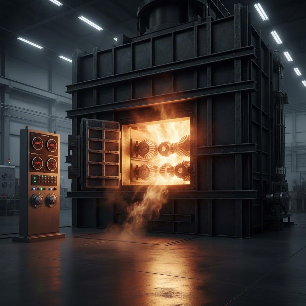
Post-Weld Heat Treatment Procedures
Your weld looks perfect, the defect inspection came back clean, and you're ready to call the repair complete. Not so fast. Without proper post-weld heat treatment (PWHT), that seemingly successful repair carries hidden stresses waiting to manifest as cracks during service. Post-weld heat treatment transforms a stressed, hardened weld zone into a stable, serviceable repair—and skipping this step ranks among the costliest mistakes in tool steel repair.
Think of your freshly welded component like a coiled spring under tension. The rapid heating and cooling cycles created locked-in stresses throughout the weld zone and heat-affected area. PWHT releases that tension in a controlled manner, preventing the sudden, catastrophic release that causes cracking.
Post-Weld Stress Relief Protocols by Steel Type
Stress relief heat treatment operates below the material's transformation temperature, allowing residual stresses to relax through controlled thermal expansion without altering the base metal's fundamental microstructure. The process requires balancing temperature, time, and cooling rate for each tool steel family.
For hot work steels (H-series), stress relief typically occurs between 1050-1150°F (565-620°C). Hold the component at temperature for approximately one hour per inch of thickness, with a minimum of one hour for thinner sections. These temperatures sit well below the transformation range, safely relieving stress without affecting hardness.
Cold work steels demand more careful consideration. D-series and A-series grades often require stress relief at 400-500°F (205-260°C)—significantly lower than hot work grades. Why the difference? These high-carbon, high-alloy steels experience secondary hardening at elevated temperatures. What looks like stress relief treatment at higher temperatures actually re-hardens the material, potentially increasing brittleness rather than reducing it.
The relationship between yield strength and proper heat treatment becomes critical here. Yield strength represents the stress level at which permanent deformation begins. Residual stresses from welding can approach or exceed the material's yield stress, creating conditions where the slightest additional load triggers cracking. Proper PWHT reduces these internal stresses to safe levels—typically below 20% of yield strength.
Understanding tensile strength vs yield strength helps clarify why stress relief matters. While tensile strength measures the maximum stress before fracture, yield strength indicates where permanent damage begins. Welded tool steels often have residual stresses approaching their yield strength vs tensile strength threshold, meaning they're operating dangerously close to their deformation limits before any external load is applied.
When deciding on PWHT approach, consider these factors:
- Repair extent: Minor surface repairs may need only stress relief; major repairs often require full re-hardening and tempering
- Steel grade: High-carbon and high-alloy grades demand more conservative treatments than moderate-alloy hot work steels
- Component geometry: Complex shapes with varying section thicknesses need slower heating and cooling to prevent thermal gradients
- Service requirements: Critical wear surfaces may require full heat treatment to restore hardness; structural areas may accept stress relief alone
- Previous heat treatment condition: Repairs to hardened components generally need re-hardening; annealed pieces may only require stress relief
- Access to equipment: Full heat treatment cycles require furnace capability; field repairs may be limited to torch-based stress relief
Re-Hardening After Major Weld Repairs
When does stress relief alone fall short? Major repairs involving significant material addition, complete crack removal and rebuilding, or restoration of critical wear surfaces typically require full re-hardening and tempering cycles. This approach ensures the weld zone achieves properties matching the original base metal.
Full re-hardening follows a more complex sequence: normalize or anneal first to homogenize the microstructure, then austenitize at the grade-specific temperature, quench appropriately (air, oil, or controlled atmosphere depending on grade), and finally temper to achieve desired hardness and toughness balance.
The yield strain steel experiences during this process relates directly to final properties. During quenching, the transformation from austenite to martensite creates volumetric changes that manifest as internal strain. Proper tempering relieves this strain while developing optimal carbide distribution for wear resistance. Skip or shortcut tempering, and that strain remains locked in the material—waiting to contribute to service failures.
Material properties like the steel modulus of elasticity influence how components respond to heat treatment stresses. The modulus of elasticity—measuring a material's stiffness—remains relatively constant for a given steel composition but interacts with geometry to determine distortion tendency during heating and cooling cycles. Components with varying section thicknesses experience differential thermal expansion, creating additional stresses that proper PWHT procedures must accommodate.
Improper cooling represents a primary failure cause in PWHT operations. Cool too quickly, and you've essentially created a second quench, re-introducing the exact stresses you intended to relieve. Cool too slowly on certain grades, and you risk precipitating undesirable phases that reduce toughness.
Slow cooling requirements vary by steel family:
- Hot work steels: Furnace cool to below 1000°F (540°C), then air cool; rate approximately 50°F (28°C) per hour maximum
- Cold work air-hardening: Very slow furnace cooling essential—25-50°F (14-28°C) per hour through the transformation range
- Cold work oil-hardening: Moderate cooling rates acceptable; furnace cool to 400°F (205°C) minimum
- High-speed steels: Complex cooling profiles; typically require multiple tempering cycles with slow cooling between
Furnace versus torch heating presents practical considerations. Furnace heating provides uniform temperature distribution—essential for complex geometries and precision components. The controlled environment prevents oxidation and allows precise temperature monitoring throughout the cycle.
Torch heating offers field-repair capability but introduces risks. Temperature gradients across the component create differential stresses. Localized overheating can damage areas beyond the repair zone. If torch heating is necessary, use multiple torches to distribute heat evenly, monitor temperatures at multiple points with contact pyrometers, and insulate the component with ceramic blankets to slow cooling after heating.
Temperature verification throughout PWHT cycles prevents costly errors. Use calibrated thermocouples attached directly to the workpiece—furnace air temperature doesn't reflect actual component temperature, especially during heating when thermal lag creates significant differences. For critical repairs, document your time-temperature profile as quality evidence.
After completing PWHT, allow adequate stabilization time before final inspection and machining. Some stress redistribution continues for 24-48 hours after cooling completes. Rushing to final machining may introduce cutting stresses into material that hasn't fully stabilized, potentially reintroducing problems that careful heat treatment had resolved.
With proper post-weld heat treatment complete, your repair has the metallurgical foundation for reliable service. The final consideration—determining when repair makes economic sense versus replacement—brings together everything you've learned about tool steel repair into practical decision-making frameworks.
Repair Economics and Practical Decision Making
You've mastered the technical aspects of welding tool steel—but here's the question that ultimately matters: should you repair this component at all? Every die maker faces this decision regularly, weighing repair costs against replacement value while production schedules pressure for quick answers. Understanding repair economics transforms reactive scrambling into strategic decision-making that protects both your budget and your production timeline.
The welding of steel in tool applications involves significant investment—not just in the repair itself, but in downtime, heat treatment, machining, and quality verification. Can you weld steel components back to original performance? Usually yes. Should you? That depends on factors most repair guides never address.
When Tool Steel Repair Makes Economic Sense
Repair viability isn't a simple yes-or-no question. Multiple factors interact to determine whether investing in weld steel repairs delivers positive returns or simply delays inevitable replacement while consuming resources.
Consider these repair viability criteria when evaluating your next repair decision:
- Damage extent relative to component size: Repairs consuming more than 15-20% of the working surface often approach replacement cost while delivering uncertain results
- Steel grade value: High-alloy grades like D2, M2, or specialized powder metallurgy steels justify more extensive repair efforts than commodity grades
- Replacement lead time: A six-week delivery for new tooling makes repair attractive even when costs approach replacement value
- Production urgency: Rush jobs may justify premium repair costs; flexible schedules allow time for cost-optimized replacement
- Repair history: First-time repairs on quality tooling make sense; components requiring repeated repairs signal fundamental design or material issues
- Remaining service life: Tooling approaching end-of-life may not justify significant repair investment regardless of technical feasibility
- Heat treatment capability: Repairs requiring full re-hardening need furnace access—unavailable capability may eliminate repair as an option
A practical rule of thumb: if repair costs exceed 40-50% of replacement value, seriously evaluate whether that investment makes sense. Components repeatedly requiring repair often reveal underlying issues—improper material selection, inadequate design, or operating conditions exceeding specifications—that welding cannot permanently solve.
Repair Scenarios from Edge Damage to Full Restoration
Different damage types present varying repair complexity and success probability. Understanding what you're facing helps set realistic expectations and appropriate budgets.
Edge repair represents the most common and generally most successful repair category. Chipped cutting edges, worn forming radii, and minor impact damage typically respond well to welding repair when proper procedures are followed. These repairs involve relatively small weld volumes, limited heat input, and predictable metallurgical outcomes. Success rates exceed 90% for properly executed edge repairs on appropriate steel grades.
Surface buildup addresses wear from extended service—worn die faces, eroded punch surfaces, and dimensional loss from repeated forming cycles. These repairs require more extensive welding but remain highly successful when filler selection matches service requirements. The key consideration: can you add enough material for final machining while maintaining acceptable heat-affected zone properties?
Crack repair demands the most careful evaluation. Surface cracks from thermal cycling or impact may repair successfully if completely removed before welding. However, cracks penetrating deeply into critical cross-sections, cracks in highly stressed areas, or multiple crack indications often signal material fatigue beyond practical repair. When cracks keep returning despite proper repair procedures, the component is telling you something—replacement may be the only permanent solution.
Dimensional restoration combines surface buildup with precision requirements. Worn cavity details, out-of-tolerance mating surfaces, and eroded clearances all fall into this category. Success depends heavily on post-weld machining capability. If you can't hold required tolerances after welding, the repair fails regardless of weld quality.
Die Maker Considerations for Production Tooling
Production tooling decisions carry weight beyond individual component costs. A die maker evaluating repair versus replacement must consider:
- Production schedule impact: How many parts will you miss during repair versus replacement timelines?
- Quality risk: What's the cost if a repaired die fails during a critical production run?
- Inventory implications: Do you have backup tooling that allows time for optimal decisions?
- Customer requirements: Some OEM specifications prohibit welded repairs on production tooling
- Documentation needs: Certified processes may require extensive repair documentation that adds cost
The most cost-effective approach to tool steel repair? Minimizing the need for repairs in the first place. Quality tooling design, appropriate material selection, and proper manufacturing processes dramatically reduce repair frequency throughout tooling service life.
For operations seeking to reduce repair dependency, investing in precision-engineered tooling from manufacturers with robust quality systems pays dividends. IATF 16949 certified manufacturing ensures consistent quality standards, while advanced CAE simulation identifies potential failure points before they become production problems. These capabilities—available through specialized suppliers like Shaoyi's precision stamping die solutions—deliver tooling designed for longevity rather than repeated repair cycles.
When you do need repairs, approach them systematically using the techniques covered throughout this guide. But remember: the best repair strategy combines skilled execution when repairs make sense with recognition that some situations genuinely require replacement. Knowing the difference protects both your immediate budget and long-term production reliability.
Mastering Tool Steel Welding Repair Excellence
You've now walked through the complete framework for successful welding repair for tool steel—from initial grade identification through post-weld heat treatment. But knowledge alone doesn't create expertise. Mastery comes from understanding how these elements interconnect and applying them consistently across every repair you undertake.
Let's consolidate everything into actionable principles you can reference before, during, and after every tool steel repair project.
Critical Success Factors for Every Tool Steel Repair
Successful repairs don't happen by accident. They result from systematic attention to five interconnected factors that determine whether your work lasts for years or fails within days:
- Proper identification: Never assume you know the steel grade—verify through documentation, spark testing, or manufacturer records before selecting any repair parameters
- Adequate preheat: Match preheat temperatures to your specific steel family; this single factor prevents more failures than any other variable
- Correct filler selection: Choose filler metals that balance hardness requirements against crack susceptibility based on repair location and service conditions
- Controlled heat input: Use the minimum heat necessary for proper fusion; excessive heat expands the HAZ and increases crack susceptibility
- Appropriate PWHT: Complete stress relief or re-hardening cycles based on steel grade and repair extent—never skip this step on hardened tool steels
The foundation of every successful tool steel repair is patience. Rushing through preheat, skipping hydrogen control measures, or cooling too quickly saves minutes but costs hours of rework—or destroys the component entirely.
When these five factors align, even challenging repairs on high-carbon, high-alloy steels become predictable. When any single factor falls short, the entire repair system becomes unreliable.
Building Your Tool Steel Welding Expertise
Technical knowledge provides your foundation, but genuine expertise develops through deliberate practice and continuous learning. Understanding material properties like the elastic modulus of steel—which measures stiffness and resistance to elastic deformation—helps you predict how components respond to thermal stresses during welding and heat treatment.
The modulus of steel remains relatively constant for a given composition, but how that stiffness interacts with your welding procedure varies significantly based on component geometry, restraint conditions, and thermal gradients. Experienced welders develop intuition about these interactions through accumulated practice, but that intuition builds on solid theoretical understanding.
Consider tracking your repairs systematically. Document the steel grade, preheat temperature, filler metal, process parameters, and PWHT cycle for each repair. Note outcomes—both successes and failures. Over time, patterns emerge that refine your procedures and build confidence in challenging situations.
Understanding concepts like Young's modulus of steel and yielding force helps explain why certain procedures work while others fail. The elastic modulus determines how much the material deflects under stress before permanent deformation begins. Materials with high modulus values resist deflection but may concentrate stresses at weld interfaces if thermal management falls short.
For those seeking to minimize repair frequency altogether, the ultimate solution lies in superior initial tooling quality. Precision-engineered dies manufactured under rigorous quality systems experience fewer service failures and require less frequent repair intervention. Operations evaluating new tooling investments benefit from working with manufacturers who combine rapid prototyping capabilities—sometimes delivering prototypes in as few as 5 days—with proven production quality.
Shaoyi's engineering team exemplifies this approach, achieving a 93% first-pass approval rate through comprehensive mold design and advanced fabrication capabilities. Their precision stamping die solutions deliver cost-effective tooling tailored to OEM standards, reducing the repair burden that consumes resources and disrupts production schedules.
Whether you're executing repairs on existing tooling or evaluating investments in new dies, the principles remain consistent: understand your materials, follow systematic procedures, and never compromise on the fundamentals that separate reliable repairs from costly failures. This guide provides your reference framework—now the expertise develops through application.
Frequently Asked Questions About Welding Repair for Tool Steel
1. What welding rod to use on tool steel?
Filler metal selection depends on your specific tool steel grade and repair requirements. For matching hardness on wear surfaces, use composition-matched fillers like H13-type rods for hot work steels or D2-specific electrodes for cold work grades. For crack-prone repairs, consider undermatching (softer) fillers or nickel-bearing electrodes that reduce crack susceptibility. Always use low-hydrogen designations (EXX18 classifications) to prevent hydrogen-induced cracking, and store electrodes in heated rod ovens at 250-300°F before use.
2. Can D2 tool steel be welded?
Yes, D2 tool steel can be welded, but it requires elevated caution due to its crack-sensitive nature with 1.4-1.6% carbon content. Essential requirements include preheating to 700-900°F (370-480°C), using low-hydrogen electrodes, maintaining interpass temperatures below 950°F, and applying proper post-weld heat treatment. For critical repairs using D2 filler material, fully anneal the component before welding and re-harden afterward. Many professionals prefer slightly undermatching fillers like H13-type for non-critical wear zones to improve crack resistance.
3. What preheat temperature is needed for welding tool steel?
Preheat temperatures vary by tool steel family. Hot work steels (H-series) require 400-600°F (205-315°C), cold work air-hardening grades (A-series) need 400-500°F (205-260°C), high-carbon D-series steels demand 700-900°F (370-480°C), and high-speed steels require 900-1050°F (480-565°C). Use temperature-indicating crayons or infrared pyrometers to verify temperatures, and allow adequate soak time for heat to penetrate heavy sections completely.
4. How do you prevent cracking when welding hardened steel?
Preventing cracks requires a multi-factor approach: adequate preheat to slow cooling rates, low-hydrogen electrodes stored properly in heated ovens, controlled interpass temperatures matching preheat levels, and appropriate post-weld heat treatment. Additionally, grind cracks completely before welding, use proper welding sequence to manage heat distribution, and consider post-weld hydrogen bakeout at 400-450°F for 1-2 hours. Environmental controls matter too—avoid welding when humidity exceeds 60%.
5. When should you repair tool steel versus replace it?
Repair makes economic sense when costs stay below 40-50% of replacement value, damage affects less than 15-20% of working surfaces, and the component hasn't required repeated repairs. Consider repair lead time versus replacement delivery, production urgency, and remaining service life. For precision stamping dies and critical production tooling, investing in IATF 16949 certified manufacturing with CAE simulation—like Shaoyi's precision solutions—often reduces long-term repair frequency while ensuring consistent quality.