 Small batches, high standards. Our rapid prototyping service makes validation faster and easier —

In-Die Tapping for Automotive Stamping: Servo vs Mechanical Guide
TL;DR
In-die tapping for automotive stamping is an advanced manufacturing process that integrates threading operations directly into the progressive die, eliminating the need for costly secondary processing. By synchronizing tapping heads with the press stroke, manufacturers can achieve production speeds exceeding 200 strokes per minute (SPM) while maintaining the “zero defect” quality standards required by automotive OEMs. This technology significantly reduces labor costs, WIP (work-in-progress) inventory, and floor space requirements.
The Business Case: Why Automotive Stamping Needs In-Die Tapping
The automotive industry’s relentless drive for efficiency has made the elimination of secondary operations a strategic priority. Traditionally, stamped parts requiring threaded holes were moved to a secondary station for manual or semi-automated tapping. This “process break” introduces multiple failure points: increased handling costs, potential for part mix-ups, and slower total throughput. Integrating tapping into the stamping die transforms this workflow into a continuous, single-pass operation.
Cost and Speed Advantages
The primary financial driver is the reduction in cost-per-part. By utilizing the press’s existing motion, in-die tapping units can produce finished parts at rates that rival the stamping press itself—often up to 250 SPM for small diameters. This is significantly faster than standalone tapping machines. Furthermore, the capital cost of a reusable tapping unit (which can be moved between dies) is often lower than purchasing a dedicated secondary tapping machine.
Zero Defect Culture
Automotive OEMs demand strict quality control. In-die systems inherently improve quality by ensuring thread location is precise relative to other stamped features, often holding tolerances within 0.001–0.002 inches. Integrated sensors detect tap breakage or misfeeds immediately, stopping the press before thousands of defective parts are produced. This capability is essential for suppliers adhering to IATF 16949 standards.
For manufacturers facing capacity constraints or those who prefer not to manage the technical complexities of in-house tooling, outsourcing to established leaders is a viable strategy. Accelerate your automotive production with Shaoyi Metal Technology, whose comprehensive stamping solutions bridge the gap from rapid prototyping to high-volume manufacturing using presses up to 600 tons.
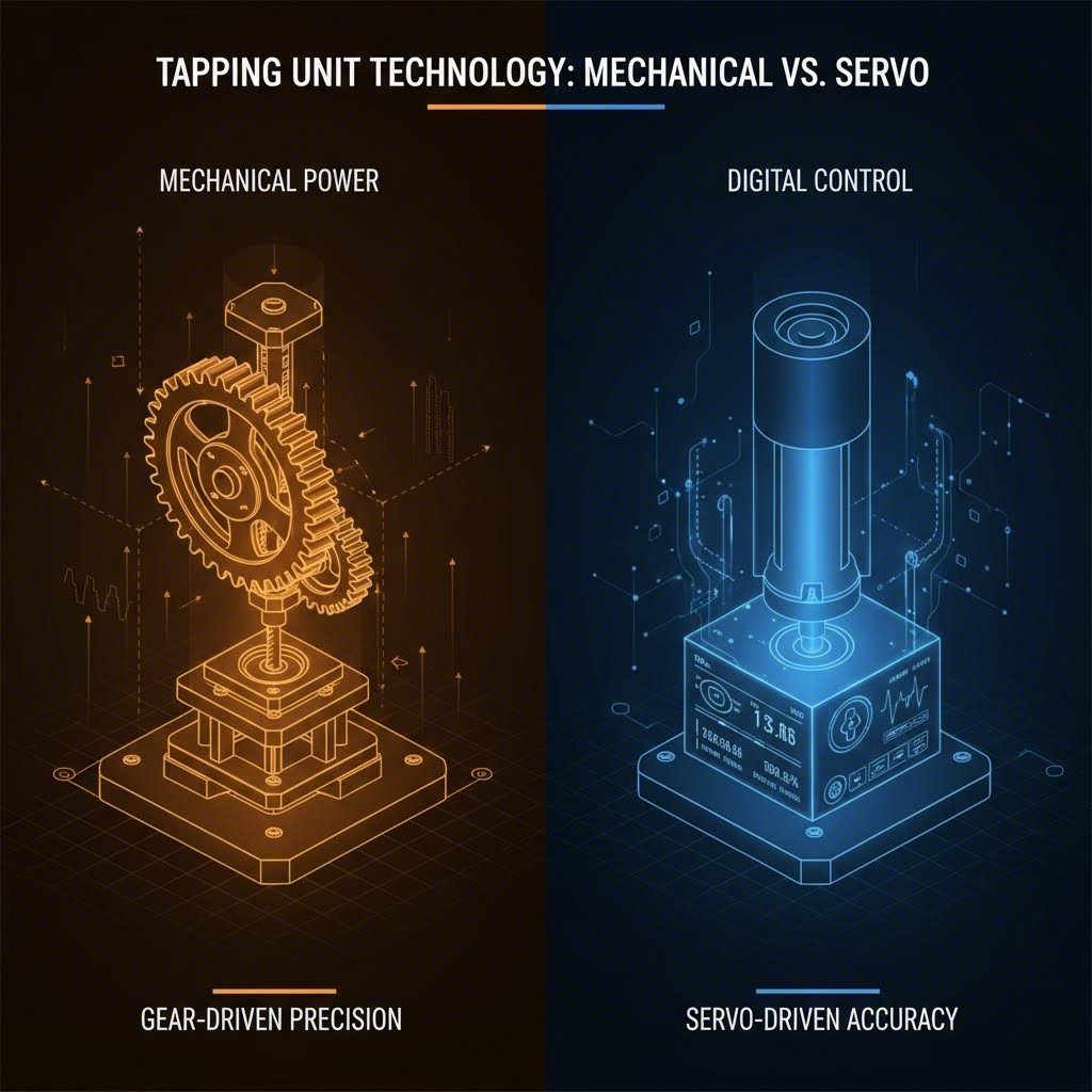
Core Technology Comparison: Servo vs. Mechanical Systems
Selecting the right drive mechanism is the most critical technical decision for engineers. The choice between mechanical and servo-driven units depends on volume, part complexity, and budget.
Mechanical In-Die Tapping
Mechanical units are the industry workhorses. They are driven directly by the press stroke, typically using a rack-and-pinion or lead screw mechanism. This synchronization ensures that the tap enters and exits the material in perfect time with the press cycle.
Pros: Lower initial cost, robust durability, simple maintenance, and no need for external power sources.
Cons: Speed is tied rigidly to the press; limited flexibility for varying thread depths without retooling.
Servo-Driven In-Die Tapping
Servo systems utilize independent motors to drive the tapping spindles. This decouples the tapping action from the press ram speed, allowing for programmable control over speed, torque, and dwell time.
Pros: precise control for complex parts, ability to “rapid reverse” to save cycle time, and capability to tap large diameters without slowing the main press.
Cons: Higher upfront investment (2-4x cost of mechanical), requires electrical integration, and more complex maintenance.
| Feature | Mechanical Systems | Servo Systems |
|---|---|---|
| Drive Source | Press Stroke (Direct Link) | Independent Servo Motor |
| Flexibility | Low (Fixed Ratio) | High (Programmable) |
| Cost | Low to Moderate | High |
| Best For | High-volume, consistent parts | Complex parts, varying depths |
| Maintenance | Simple mechanical repairs | Requires specialized tech |
According to IMS Buhrke-Olson, mechanical systems remain the ideal choice for straightforward, high-volume runs, while servo systems offer the necessary adaptability for lines producing multiple part variations.
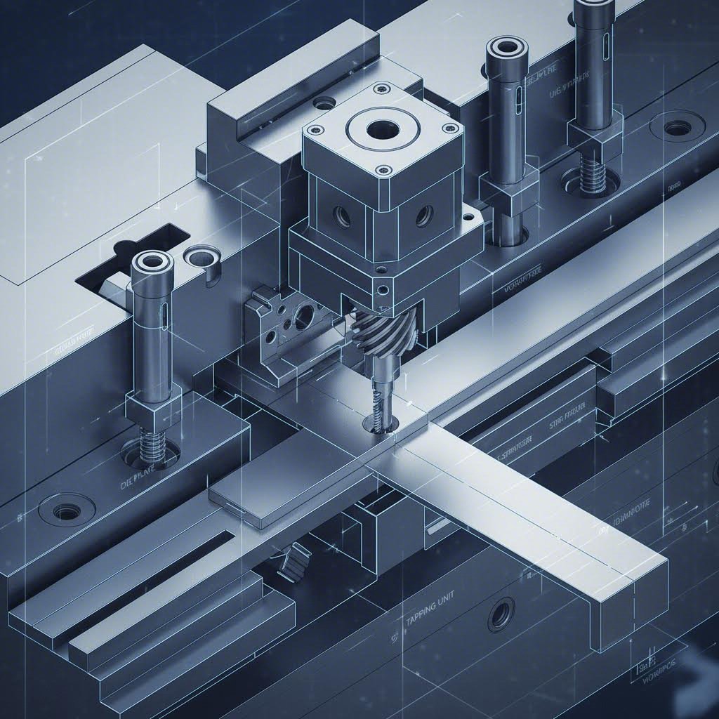
Technical Configuration: Top-Down, Bottom-Up, and Strip-Following
The geometry of the stamped part and the design of the progressive die dictate the physical configuration of the tapping unit. Die designers must choose a setup that accommodates material movement, specifically “strip lift.”
Top-Down Tapping
This is the standard configuration for flat parts with minimal strip lift. The tapping unit is mounted on the upper die shoe and descends with the press ram. It is the most common and cost-effective method, capable of high speeds. However, it requires the strip to remain relatively stationary and flat during the tapping portion of the stroke.
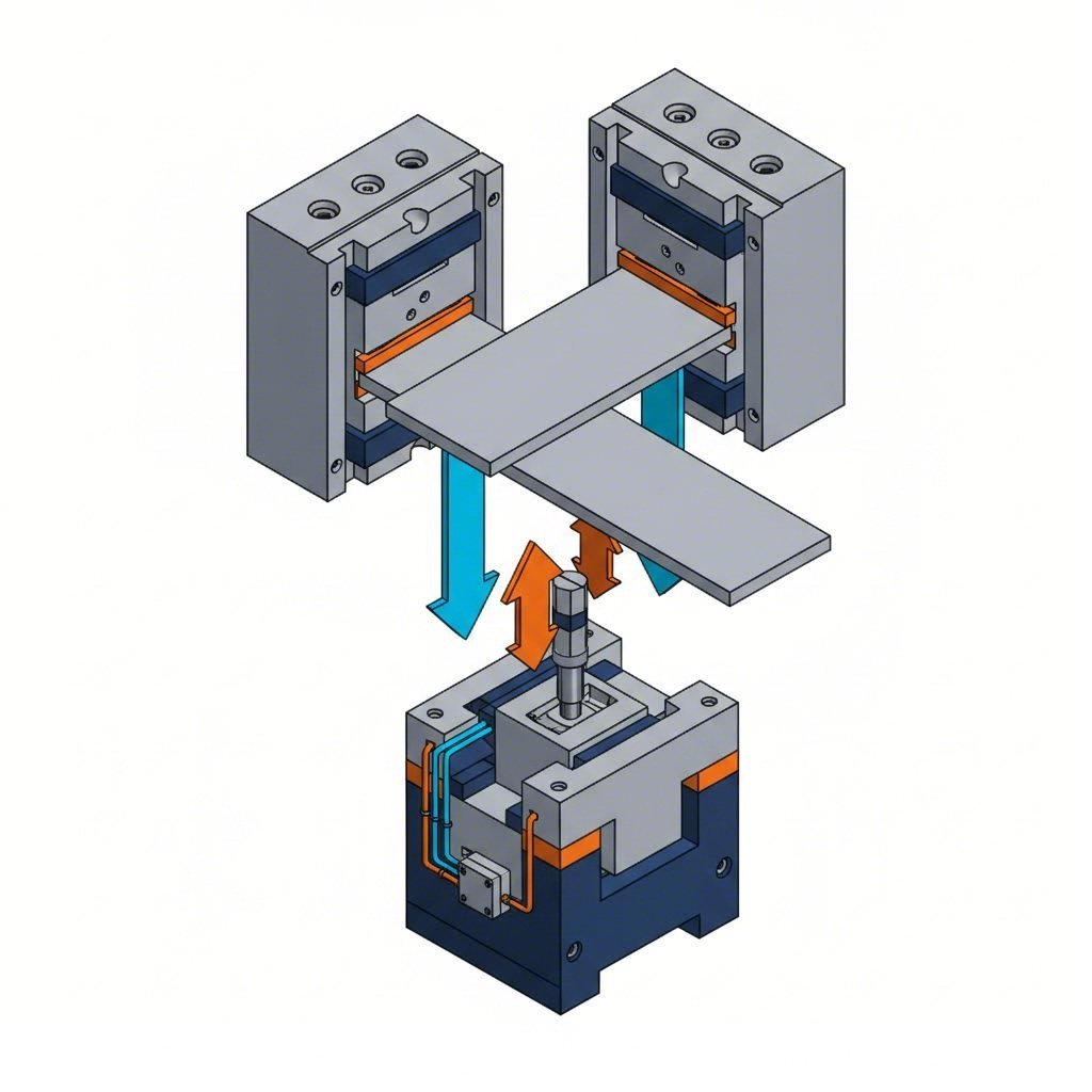
Bottom-Up Tapping
When a progressive die requires significant strip lift (to clear forms or extrusions), the material moves vertically between stations. In these cases, a bottom-up unit is mounted to the lower die shoe. The strip is pushed down onto the tap, or the tap rises to meet the strip. The Fabricator notes that bottom-up tapping effectively compensates for material movement, using the press stroke to position the part rather than drive the rotation, which is useful when strip lift exceeds standard limits.
Strip-Following Technology
For applications where the press stroke is short or the strip lift is excessive (over 2.5 inches), strip-following units are the solution. These units “travel” with the strip for a portion of the stroke, effectively extending the tapping window. This allows the tap to complete its thread cycles even in high-speed, short-stroke presses where a stationary unit would not have enough time to enter and exit the hole.
Operational Excellence: Lubrication, Protection, and Maintenance
Implementing in-die tapping requires a disciplined approach to die maintenance and protection to prevent catastrophic tool damage.
Lubrication and Cooling
Tapping generates significant heat and friction. Modern in-die units often feature “Through Tool Coolant” capabilities, delivering high-pressure oil directly to the cutting edge. This not only lubricates the thread but also evacuates chips that could otherwise jam the tool or mar the part surface.
Die Protection Sensors
To run “lights out” or with minimal supervision, robust sensing is mandatory. Sensors should monitor:
1. Tap Presence: Verifying the tap is still intact after every cycle.
2. Strip Position: Ensuring the hole is perfectly aligned before the tap enters.
3. Torque Limits: Servo systems can detect torque spikes (indicating a dull tap or undersized hole) and stop the press instantly.
Quick-Change Maintenance
Downtime kills profitability. Leading manufacturers like Automated Tapping Systems utilize twist-lock lead screw assemblies, allowing operators to change a worn tap in seconds without removing the unit from the press. Regular maintenance schedules should focus on cleaning pitch gears and verifying the timing synchronization to prevent thread stripping.
Strategic Value of In-Die Integration
The transition to in-die tapping represents a maturity milestone for automotive stamping operations. It moves a manufacturer from being a simple provider of blanks to a deliverer of finished, value-added components. While the engineering learning curve exists—particularly regarding stroke timing and strip lift management—the ROI from eliminating secondary logistics and achieving zero-defect throughput is undeniable.
For plant managers, the decision ultimately balances the upfront engineering cost against the long-term savings in labor and floor space. Whether choosing a robust mechanical unit for dedicated high-volume runners or a versatile servo system for a family of parts, in-die tapping is a cornerstone of modern, competitive automotive manufacturing.
Frequently Asked Questions
1. What is the maximum speed for in-die tapping?
Production speeds depend heavily on the tap size, material, and thread depth. For small diameter holes (e.g., M3 to M5) in non-ferrous metals, speeds can exceed 200 SPM. Larger diameters or harder materials like high-strength steel will typically run slower, often between 60 to 100 SPM, to manage heat and tool life.
2. Can in-die tapping be retrofitted to existing dies?
Yes, but it requires sufficient die space. Tapping units are compact, but the die must have an open station or enough room between existing stations to accommodate the unit and the necessary stripper travel. Consulting with a die designer is essential to determine if a retrofit is feasible or if a new die build is required.
3. How do you prevent chips from damaging the die?
Chip management is critical. Most in-die systems use specialized taps (like roll form taps) that form threads without creating chips. If cutting taps are used, high-pressure through-tool coolant and vacuum systems are employed to flush and evacuate chips immediately, preventing them from contaminating the die or marking the parts.