 Small batches, high standards. Our rapid prototyping service makes validation faster and easier —
  EN
EN

Nearly 40% of premature cooling system failures in modern vehicles begin with fatigued mounting hardware. For Tier-1 engineers, maintaining structural integrity during extreme engine vibration remains a major challenge.
At Shaoyi Metal Technology, we specialize in automotive compressor bracket manufacturing to address these complex durability issues. As an IATF 16949 certified partner, we use advanced 160T-1200T press lines for precision components that meet rigorous industry standards.
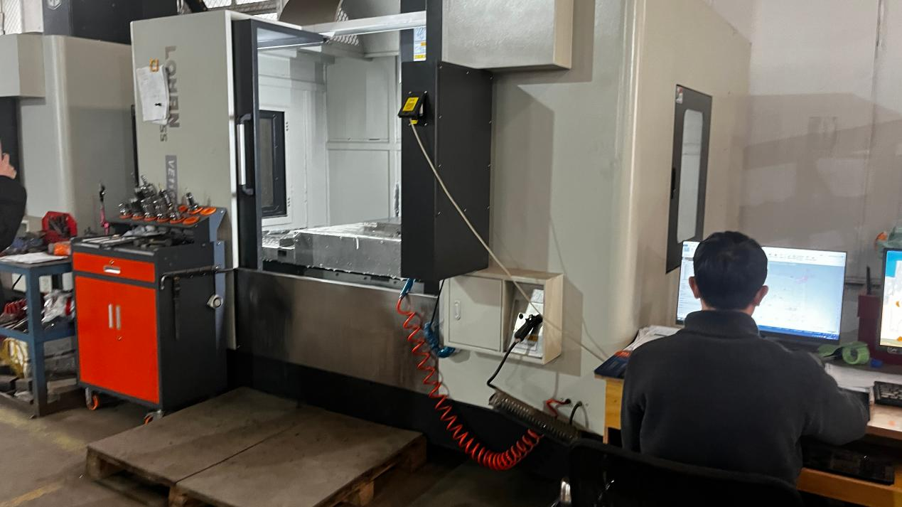
Progressive die strip layout and tooling design for precision automotive compressor brackets
This guide examines our proven methods for automotive HVAC bracket stamping, with emphasis on 2.5mm–4.5mm material thickness and 8%–10% punch-die clearance. It also explains key requirements for automotive HVAC bracket stampings, including HSLA-340 springback compensation and 720-hour salt spray resistance.
Key Takeaways
- Shaoyi Metal Technology operates IATF 16949 certified facilities with 160T-1200T press capacity.
- Achieving ±0.05mm hole tolerance is essential for mounting precision.
- Proper punch-die clearance (8%–10%) prevents premature material fatigue.
- Surface flatness of 0.15mm is critical for vibration durability in high-stress environments.
- Advanced springback compensation is required when working with HSLA-340 steel grades.
Define the Compressor Bracket's Load, Interface, and Manufacturing Requirements
Successful production of an AC compressor mounting bracket requires a clear view of loads and interface limits. Before tooling design begins, we conduct a thorough engineering review to confirm that the part meets every performance requirement.
Step 1: Map the Compressor Mounting Loads and Vibration Inputs
Identify cyclic loads, resonance risks, and fatigue-critical bracket zones
We study operating conditions to identify potential resonance risks that may weaken structural integrity. Mapping cyclic loads reveals fatigue-critical zones requiring reinforcement during design.
Separate static strength requirements from vibration fatigue durability under compressor operation
Static load capacity and long-term vibration resistance demand separate evaluation. The compressor mounting bracket must withstand continuous operating stress without developing material fatigue.
Step 2: Convert Vehicle Interface Data into Stamping Requirements
Control mounting-hole location, hole concentricity, flange position, and mating-surface flatness
Precision is essential when vehicle interface data becomes manufacturing specifications. We control mounting-hole location, hole concentricity, flange position, and mating-surface flatness for an accurate engine-bay fit.
Establish the 2.5mm–4.5mm thickness range and applicable automotive drawing standards
We set material thickness between 2.5mm and 4.5mm, balancing low weight with structural rigidity. This range follows standard automotive HVAC bracket stamping protocols for consistent performance across production batches.
Step 3: Align the Part Plan with Shaoyi Metal Technology's Production Capability
Use our IATF 16949 certified process controls and 160T-1200T press lines during feasibility planning
Our team applies IATF 16949 certified process controls to maintain high quality throughout the manufacturing cycle. We use our flexible 160T-1200T press lines to support the specific geometry of your AC compressor mounting bracket.
Confirm annual volume, press tonnage, coil width, blank size, and downstream finishing requirements
We confirm annual volume, press tonnage, coil width, and blank size early to improve material use and press efficiency. We confirm downstream finishing needs, including specialized coatings, so the final compressor mounting bracket is ready for immediate assembly.
Select Steel or Aluminum for Strength, Formability, and Corrosion Performance
Material selection balances structural integrity with manufacturing efficiency in each component. We assess metal mechanics against the rigorous demands of modern vehicle vibration environments.
Compare SPCC, HSLA-340, and 6061-T6 Aluminum Before Tool Design
Selecting SPCC steel, HSLA-340 steel, or 6061-T6 aluminum requires understanding how each material behaves under pressure. Aluminum reduces weight, while steel provides greater fatigue resistance for high-load compressor mounts.
|
Material |
Strength |
Formability |
Primary Use |
|
SPCC Steel |
Moderate |
Excellent |
General Brackets |
|
HSLA-340 |
High |
Moderate |
Structural Support |
|
6061-T6 Aluminum |
High |
Low |
Lightweight Parts |
Relate HSLA-340 Steel to SPCC and Q235B Selection Decisions
When comparing SPCC vs. Q235B, we seek the most cost-effective option for standard applications. Higher performance requirements, however, may justify more advanced alloys.
Explain why HSLA-340 may reduce section weight while increasing forming complexity
Using HSLA-340 steel reduces bracket thickness without sacrificing structural rigidity. This mass reduction is essential for modern fuel efficiency, but stronger tooling must manage greater forming springback.
Use SPCC or comparable low-carbon steel when ductility and economical forming are priorities
For complex geometries, SPCC steel remains the industry standard because of its high ductility. It supports intricate bends and deep draws that could crack higher-strength materials.
Verify Material Certification and Coil Consistency
We require strict material certification so every batch meets our engineering specifications. Consistency across the entire coil supports stable production.
Check thickness, yield strength, tensile strength, elongation, surface condition, and heat-lot traceability
Our quality team checks thickness, yield strength, tensile strength, elongation, surface condition, and heat-lot traceability. Detailed shipment records show whether the 6061-T6 aluminum or steel will match simulation predictions.
Prevent material variation from shifting springback, hole quality, or fatigue performance
Small changes in material properties can create major problems during mass production. Controlling these variables prevents inconsistent hole diameters and premature fatigue failure in the field.
Build the Stamping Process Around 2.5mm–4.5mm Material Thickness
High-quality results in automotive HVAC bracket stamping begin with control of the 2.5mm to 4.5mm thickness range. This gauge demands disciplined stamping process design to protect structural integrity and dimensional accuracy. We tailor production methods for heavier material, so each bracket meets strict performance standards.
Step 4: Establish the Blank, Grain Direction, and Forming Sequence
Orient the rolling direction to reduce cracking and control directional springback
We study the material grain to optimize the blank layout. Aligning the rolling direction with primary bend axes helps reduce the risk of cracking during high-stress forming. This alignment also controls directional springback and supports tight tolerances.
Sequence piercing, blanking, bending, flanging, restriking, and calibration operations
We begin with precise blanking to establish the part foundation. Piercing, bending, and flanging follow, with each station protecting the material structure. Finally, restriking and calibration secure the final geometry, so the automotive HVAC bracket stampings meets every design specification.
Match Press Capacity to Forming Force and Part Stability
Use 160T-1200T press lines according to blank size, material grade, draw depth, and die shut height
We use 160T-1200T press lines for brackets with different sizes and complexities. Our team chooses each press according to the required draw depth and die shut height. This flexibility maintains optimal forming conditions across different material grades.
Reserve tonnage for peak forming loads, pad force, stripping, and safe process margins
Safety and consistency guide our stamping process design. We reserve extra tonnage for peak forming loads and required pad force. These safe process margins reduce equipment strain and extend tooling life.
Design Carrier Strips, Pilots, and Transfer Features for Repeatability
Maintain accurate part positioning through progressive stations and prevent strip distortion
Pilots and robust carrier strips keep parts positioned accurately. They guide material through each progressive station with high precision. This approach prevents strip distortion and places every bracket consistently.
Provide safe access for lubrication, scrap evacuation, sensors, and die maintenance
Our dies include integrated systems for efficient lubrication and scrap removal. Sensors monitor production throughout the line in real time, adding another layer of quality assurance. These systems provide easy die maintenance and keep production running smoothly.
Set Punch-Die Clearance for Clean Holes and Reliable Tool Life
Precision in HVAC compressor bracket manufacturing starts with the critical balance of punch-die clearance. We protect every hole by calculating the punch-to-die gap for optimal piercing quality.
Apply 8%–10% Clearance per Side to the Specified Material
Calculate clearance from actual material thickness rather than nominal assumptions
We never rely on nominal thickness when setting tooling. We measure the incoming coil to determine the required punch-die clearance.
Adjust the range for SPCC, HSLA-340, hole diameter, edge condition, and production volume
Our standard starting point is 8%–10% per side, but material properties guide the final adjustment. HSLA-340 needs different treatment than SPCC to maintain consistent burr control.
Control Fracture Progression During Piercing
Use punch and die edges that produce a stable shear zone and limited rollover
We create a clean, stable shear zone that limits rollover at the entry point. Sharp tool edges help fracture lines meet accurately during the piercing stroke.
Monitor burr height, slug pulling, slug stacking, and edge chipping during tryout
During initial tryout, we monitor common defects closely. We measure burr height and check slug pulling or stacking, which can shorten die life.
Protect Small or Closely Spaced Holes from Deformation
Check minimum hole-to-edge and hole-to-hole distances against thickness and material strength
Small features can deform during stamping. We verify hole spacing against the material's yield strength to prevent tearing or warping.
Use piloting, stripper control, and sequencing to protect hole position through later bends
We use robust piloting and active stripper control to secure the part. This preserves hole accuracy through later bending operations.
|
Material Type |
Thickness (mm) |
Clearance per Side (%) |
Primary Focus |
|
SPCC |
2.5 – 3.5 |
8% |
Burr Control |
|
HSLA-340 |
3.0 – 4.5 |
10% |
Piercing Quality |
|
6061-T6 Al |
3.0 – 4.0 |
9% |
Edge Integrity |
Hold Critical Holes, Flatness, and Bend Geometry Within Functional Tolerances
Achieving tight dimensional control requires disciplined stamping engineering. We maintain high precision so every bracket integrates perfectly with the vehicle assembly.
Achieve the Critical Hole Tolerance of ±0.05mm
High-performance brackets require a critical hole tolerance for proper bolt fitment and balanced load distribution. Meeting the hole concentricity tolerance of ±0.05mm requirement demands rigorous attention during tool design.
Define whether the tolerance applies to hole size, true position, or hole concentricity on the drawing
We clarify each dimension's intended function on your engineering prints. We adjust our manufacturing strategy to meet the exact specification for hole size, true position, or concentricity.
Control punch alignment, die wear, strip pitch, pilot engagement, and post-form movement
We apply strict process controls throughout production to maintain consistency. Our team monitors the following factors to prevent deviation:
- Precision punch alignment to minimize shear stress.
- Regular monitoring of die wear to maintain hole quality.
- Optimized strip pitch and pilot engagement for accurate positioning.
- Compensation for post-form movement to ensure final dimensions remain stable.
Maintain Surface Flatness Within 0.15mm
Stable mounting planes prevent vibration and keep the compressor flush against the engine block. We target a surface flatness 0.15mm to create a reliable interface for every mating component.
Use restrike, calibration, controlled pad pressure, and balanced forming to reduce distortion
We use advanced forming techniques to reduce internal stresses that cause warping. Through restrike operations and precise calibration, we consistently meet your flatness requirements.
Inspect mounting planes after trimming, bending, coating, and part handling
Quality control continues throughout production. We inspect the part after trimming, bending, protective coating, and handling to verify it remains within tolerance.
Manage Bend Angle, Flange Location, and Datum Relationships
Bracket structural integrity depends on accurate bend angles and flange positions. We define functional datums that align with the compressor, engine, and vehicle assembly interfaces.
Establish functional datums that reflect compressor, engine, and vehicle assembly interfaces
We anchor measurements to these specific interfaces so the bracket performs as intended in the field. This approach reduces assembly errors and improves the HVAC system's overall fit.
Specify realistic tolerances that protect assembly performance without creating unnecessary tooling cost
We balance performance with economic efficiency. Realistic tolerances for our functional datums protect assembly performance and avoid costs from over-engineering.
Compensate for Springback in High-Strength Steel Bending
Managing high-strength steel's natural elasticity is a critical phase in our manufacturing process. During high-strength steel bending, the material tries to return to its original flat shape after forming pressure is released. This springback can damage the fit of HVAC compressor brackets unless we address it early in design.
Predict Springback in HSLA-340 Before Cutting Production Steel
Account for yield strength, bend radius, material direction, thickness, and forming strain
We study the mechanical properties of HSLA-340 steel to predict its response during stamping. Yield strength, thickness, and rolling-grain direction strongly affect the final geometry. By calculating forming strain at each bend radius, we establish the expected deviation.
Use forming simulation and measured tryout data to identify angle opening and flange shift
Our team uses advanced FEA software to simulate bending before cutting any tool steel. We compare these predictions with physical tryout data to locate areas prone to angle opening or flange shift. This proactive approach to springback compensation improves the accuracy of our initial tool designs.
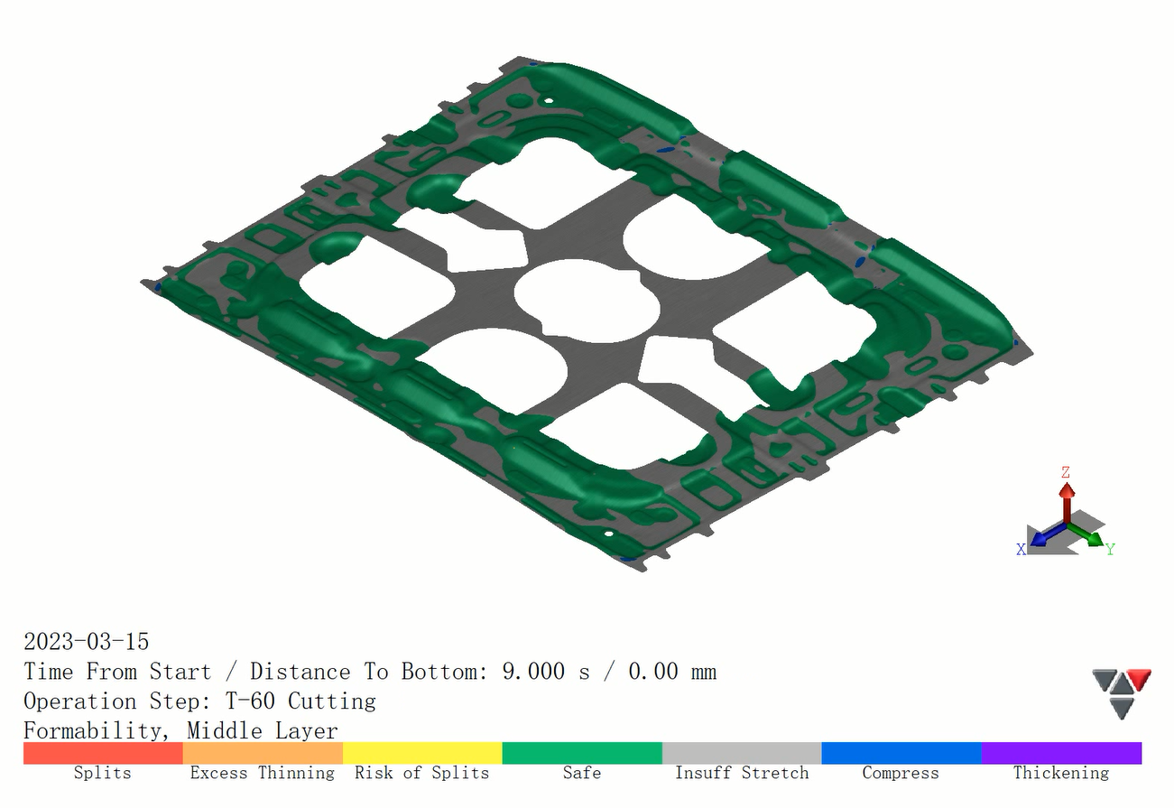
FEA simulation and springback compensation for HSLA-340 automotive bracket bending in stamping die
Apply Die Compensation and Corrective Forming
Modify overbend angles, die radii, cam geometry, and restrike stations to recover target dimensions
To meet required tolerances, we apply precise springback compensation methods within our die sets. We add overbend angles or adjust die radii to counter the material's natural tendency to open. For complex geometries, dedicated cam-driven stations or secondary restrike operations force each part into its final, stable configuration.
Balance compensation against cracking, thinning, tool wear, and excessive residual stress
Although we seek exact dimensions, we balance adjustments carefully to protect the bracket's structural integrity. Too much compensation can cause localized thinning, surface cracking, or greater tool wear. We monitor residual stress so our HSLA-340 steel components remain durable under cyclic loading.
|
Method |
Primary Benefit |
Risk Factor |
|
Overbending |
Simple to implement |
Potential for thinning |
|
Restrike Stations |
High dimensional accuracy |
Increased cycle time |
|
Die Radius Adjustment |
Reduces stress concentration |
Tool wear acceleration |
Validate Springback After Each Major Tooling Revision
Compare first-off parts with CAD datums and tolerance zones
After producing the initial tools, we conduct rigorous validation. We compare first-off parts with master CAD datums to measure our springback compensation strategy's effectiveness. This confirms that the high-strength steel bending process meets all engineering specifications.
Freeze the corrected geometry only after dimensional stability across multiple production runs
We do not finalize tooling until results remain consistent across multiple production cycles. Dimensional stability shows that our springback compensation works. After confirming that parts stay within specified tolerance zones, we officially release the geometry for full-scale manufacturing.
Engineer Vibration Fatigue Durability into Bracket Geometry
We prioritize vibration fatigue durability for components exposed to harsh automotive environments. Early structural reinforcement manages stresses that can cause material failure over time.
Reinforce Load Paths Without Creating New Stress Concentrations
We design each bracket's geometry to preserve structural integrity. The load path distributes forces across the mounting surface, preventing localized strain.
Use appropriate bend radii, beads, ribs, gussets, and flange widths around compressor mounting points
Our geometry strategy uses targeted features to increase stiffness without unnecessary weight. We incorporate these elements to improve vibration fatigue durability:
- Generous bend radii to reduce stress at transition points.
- Strategic beads and ribs to increase the section modulus.
- Gussets placed at high-load junctions to prevent deflection.
- Optimized flange widths to provide lateral support.
Avoid sharp internal corners, abrupt thickness transitions, and unsupported tabs
Sharp internal corners act as stress risers that can initiate cracks under load. We avoid them through smooth transitions that distribute stress across the part.
Evaluate Cyclic Compressor Loads and Resonance Behavior
Managing the dynamic forces from compressor cyclic loads helps prevent premature mechanical failure. We perform rigorous resonance analysis to keep the bracket's natural frequency outside the system's operating range.
Review excitation frequency, operating speed range, mount stiffness, and bracket natural frequency
We analyze interactions between the compressor and mounting system to identify potential risks. Matching bracket stiffness to system requirements minimizes harmonic amplification.
Use finite element analysis and physical vibration testing to locate fatigue-critical areas
Our team uses finite element analysis (FEA) to simulate real-world conditions. We validate the models through physical vibration testing, confirming the bracket withstands compressor cyclic loads without degradation.
Control Fatigue-Sensitive Manufacturing Features
A well-designed part can still fail when manufacturing introduces defects. We control production variables closely so the final product meets our standards for vibration fatigue durability.
Inspect pierced edges, burr orientation, forming marks, cracks, and local thinning
We monitor stamping to prevent micro-cracks and excessive thinning. Correct burr orientation matters because sharp edges can initiate fatigue cracks during operation.
Confirm that welds, fasteners, coating interfaces, and contact points do not undermine durability
We evaluate welds, fasteners, coating interfaces, and contact points for structural effects. These processes must not create brittle zones or stress concentrations that compromise long-term bracket performance.
Choose Between Single-Stage Tooling and Multi-Stage Progressive Dies
When we engineer compressor brackets, tooling architecture shapes long-term manufacturing success. The right method balances upfront capital with ongoing operating efficiency.
Compare Economics, Output, and Flexibility
The main difference is how material moves through the press. Single-stage stamping usually requires manual handling between stations, allowing design flexibility but slowing cycle times.
By contrast, progressive die tooling moves the strip through several stations in one continuous motion. This automation raises throughput and maintains consistent quality during large production runs.
Use Volume and Part Complexity to Select the Economic Path
To improve tooling economics, we must look beyond the die's initial price. We assess total ownership cost by studying each method's effect on long-term production goals.
Compare tool amortization, press utilization, labor, scrap, maintenance, and changeover costs
The following table summarizes key operational differences between these two manufacturing strategies:
|
Factor |
Single-Stage Stamping |
Progressive Die Tooling |
|
Labor Cost |
Higher (Manual handling) |
Lower (Automated) |
|
Changeover Time |
Fast and Simple |
Complex and Lengthy |
|
Scrap Rate |
Higher potential |
Optimized via strip layout |
Assess whether a progressive die is justified by annual demand and design stability
A progressive die tooling is often the better choice when annual demand is high and the part design is mature. Because these tools require substantial upfront investment, they suit programs with stable geometry over several years.
If your project includes frequent engineering changes or low-volume needs, single-stage stamping offers the agility to adapt. It avoids the burden of costly tool modifications. We help weigh these factors so your investment matches your production roadmap.
Design for Manufacturing Review Before Progressive Die Release
We invite Tier-1 engineers to collaborate with us early on compressor bracket design. Our comprehensive DFM review confirms that each component is ready for high-volume production before expensive tooling begins.
Step 5: Submit CAD Data for a Complimentary Feasibility Review
Encourage Tier-1 engineers to submit 3D CAD files in STEP or IGES format
Please submit your 3D models as STEP CAD files or IGES CAD files to begin. These industry-standard formats let our engineers conduct a detailed tooling feasibility analysis of your geometry.
Review part orientation, strip layout, piercing access, bend sequence, die clearance, and press fit
Our team evaluates key manufacturing factors, including part orientation and the optimal strip layout. We verify piercing access, bend sequence, and die clearances to ensure a precise press fit for your HVAC compressor.
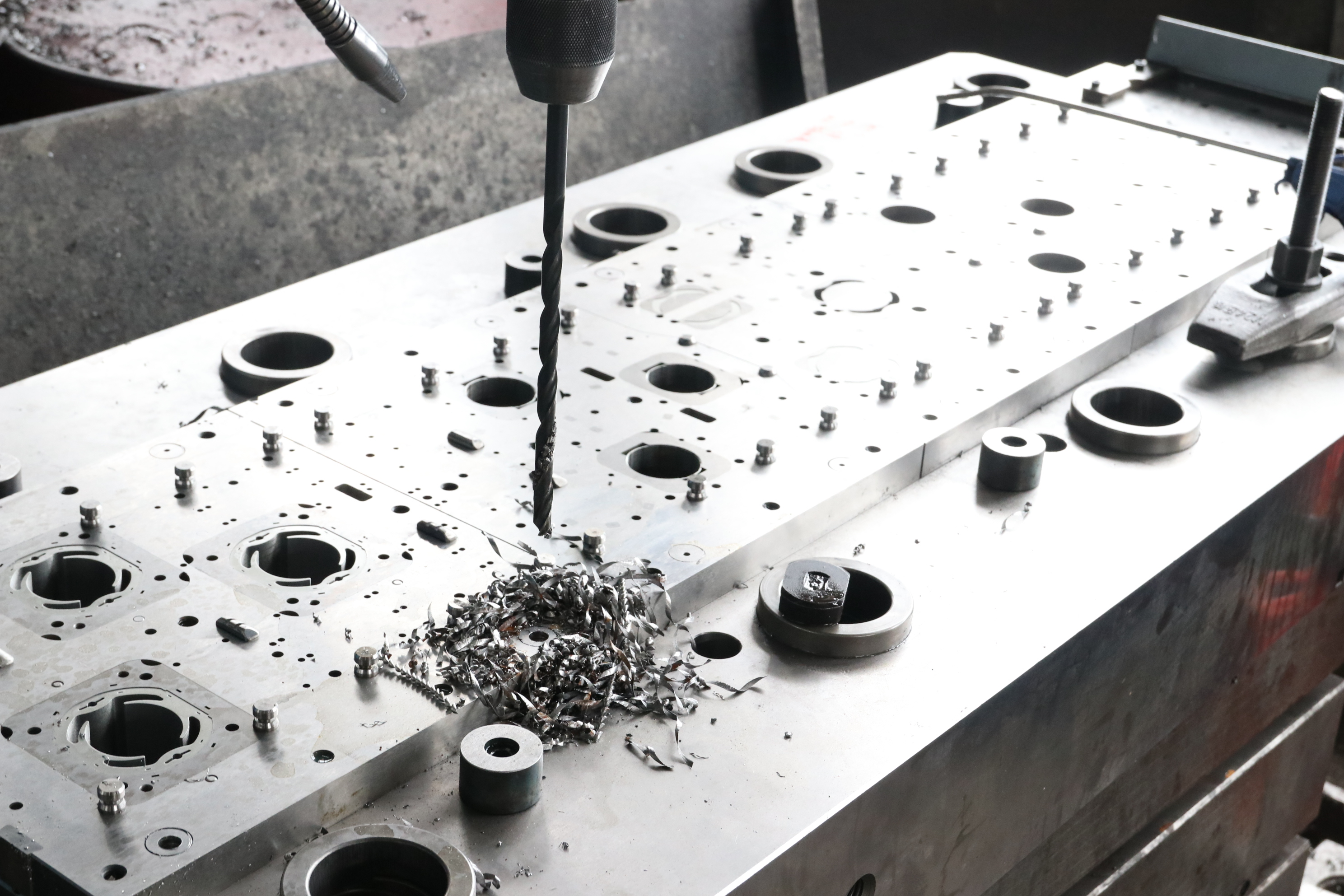
Progressive die strip layout and tooling design for precision automotive compressor brackets
Resolve DFM Risks Before Tool Steel Is Machined
Identify inaccessible features, insufficient radii, thin ligaments, trapped scrap, and unstable carrier connections
We identify manufacturing bottlenecks, including inaccessible features and insufficient radii. We also check thin ligaments, trapped scrap, and unstable carrier connections that may cause downtime or defects during stamping.
Recommend geometry changes that improve stamping reliability without compromising compressor fit
When we detect risks, we recommend specific changes that improve stamping reliability. These changes strengthen the bracket without compromising compressor fit or functional requirements.
Use Springback Simulation to Support Design Decisions
Predict HSLA-340 deformation and propose compensation before physical tryout
High-strength materials such as HSLA-340 can challenge the forming process. We use advanced simulation software to predict deformation and calculate the necessary springback compensation before cutting any tool steel.
Return feasibility findings, critical assumptions, and dimensional risks for engineering approval
Finally, we return a detailed report with our tooling feasibility findings and critical assumptions. It identifies potential dimensional risks, so your team can grant formal engineering approval before physical tryout begins.
Apply E-Coating for 720-Hour Salt Spray Resistance
We extend stamped component life through finishing processes that exceed industry standards. Strong corrosion protection is essential for HVAC compressor brackets exposed to moisture and road debris. Our E-coating process creates a uniform, durable barrier that preserves structural integrity throughout the vehicle's lifespan.
Prepare Stamped Steel for Consistent E-Coat Adhesion
Control oil, scale, burrs, cleaning, pretreatment, phosphate conversion, and rinsing conditions
Surface preparation establishes the foundation for a successful finish. We remove residual stamping oils, scale, and metallic burrs, leaving the substrate chemically clean. Our process uses multi-stage pretreatment and phosphate conversion, followed by precise rinsing, to promote strong paint adhesion.
Design drainage and venting features so recessed bracket areas receive adequate coating coverage
Effective coverage depends on liquid coating reaching every surface of the complex bracket geometry. We add strategic drainage and venting holes to prevent air pockets and liquid pooling. These features help protect even the most recessed areas with a consistent layer.
Specify the E-Coating Performance Target
Validate the requirement of 720-hour salt spray resistance using the applicable customer and laboratory method
We test finished parts through the rigorous 720-hour e-coating salt spray test. This testing confirms that brackets retain their protective properties under extreme conditions. Standardized laboratory methods verify that the salt spray resistance meets or exceeds specified automotive requirements.
Inspect coating thickness, coverage, adhesion, edge protection, and corrosion at cut or pierced edges
We inspect coating thickness and overall coverage in detail. Cut or pierced edges receive special attention because they are more vulnerable to oxidation. Verifying adhesion and edge protection keeps the component shielded from environmental degradation.
Connect Corrosion Protection with Fatigue Life
Prevent corrosion pits from becoming fatigue initiation sites near holes, bends, and mounting flanges
Corrosion is more than cosmetic; it threatens structural integrity. We prevent pits near high-stress areas, including mounting flanges and holes. These pits can initiate fatigue, so a clean surface supports the bracket's long-term fatigue life.
Confirm that coating buildup does not interfere with fastener fit or critical datums
Although we require high coverage, we control coating thickness during assembly. We ensure final buildup does not interfere with fastener fit or critical datums. This balance provides strong protection while preserving precise mechanical installation.
|
Process Stage |
Primary Objective |
Impact on Performance |
|
Surface Cleaning |
Remove oils and debris |
Ensures uniform adhesion |
|
Phosphate Conversion |
Create chemical bond |
Enhances corrosion resistance |
|
E-Coating Application |
Apply protective layer |
Provides 720-hour salt spray protection |
|
Final Inspection |
Verify thickness and fit |
Guarantees assembly precision |
Verify Dimensions, Process Capability, and PPAP Level 3 Readiness
We use advanced measurement methods to keep every bracket within strict automotive standards. Our team validates each component for reliable performance under demanding vehicle conditions.
Use CMM 3D Inspection for Critical Geometry
Measure hole position, hole size, flatness, bend angles, flange location, and datum relationships with a coordinate measuring machine
To guarantee dimensional capability, we use high-precision CMM 3D dimensional inspection. This system maps complex geometry, including hole positions and bend angles, with exceptional accuracy. These measurements confirm that each bracket fits the engine assembly correctly.
Correlate CMM results with functional gauges, fixture checks, and production inspection records
We combine our CMM 3D inspection results with physical functional gauges and fixture checks. This layered review confirms consistent production across every batch.
Document Process Controls for Automotive Approval
Prepare control plans, process flow diagrams, PFMEA outputs, material certifications, capability studies, and inspection results
Comprehensive documentation supports automotive compliance. We maintain detailed records, including process flow diagrams and PFMEA outputs, to identify and reduce risks early. Together, these records map our manufacturing quality.
Maintain traceability for tooling revisions, material lots, corrective actions, and operator checks
Traceability lets us track every component back to its origin. We record each tooling revision and material lot for complete transparency. This practice enables rapid corrective action when production deviations occur.
Prepare PPAP Level 3 Submission Evidence
Include dimensional results, sample parts, engineering change records, performance test data, and signed customer documentation
Our PPAP Level 3 package provides final evidence of manufacturing readiness. We compile dimensional results, sample parts, performance test data, signed engineering change records, and signed customer documentation.
Use PPAP Level 3 readiness to support Tier-1 supplier launch timing and customer review
Reaching PPAP Level 3 readiness marks a critical project milestone. Robust evidence supports Tier-1 supplier launch schedules and smoother customer reviews. The table below summarizes our core quality deliverables for this phase.
|
Deliverable Category |
Key Documentation |
Purpose |
|
Dimensional Data |
CMM 3D inspection reports |
Verify geometry |
|
Process Control |
PFMEA & Control Plans |
Risk mitigation |
|
Material Quality |
Certifications & Test Data |
Ensure durability |
|
Launch Readiness |
PPAP Level 3 package |
Customer approval |
Release a Production-Ready HVAC Compressor Bracket
Achieving a production-ready HVAC compressor bracket requires disciplined final engineering validation. We confirm every technical detail matches your performance requirements before full-scale production begins.
Step 6: Complete the Final Engineering Gate
Confirm material, clearance, hole tolerance, flatness, springback compensation, fatigue features, and E-coating requirements
At this stage, we audit every design parameter. We verify material properties, hole tolerances, and flatness against your assembly's exact needs. Precision is our priority, so we integrate springback compensation and fatigue-resistant features into the final design.
Approve the final CAD, control plan, inspection method, and progressive die or single-stage tool design
Before proceeding, we finalize the CAD data and establish a robust control plan. We define inspection methods to ensure consistent quality throughout the product lifecycle. For progressive dies or single-stage tooling, we optimize the design for efficiency and durability.
Step 7: Validate Production Consistency
Run representative lots across the selected 160T-1200T press line and verify dimensional capability
We use our versatile 160T-1200T press lines to run representative lots and confirm dimensional integrity under real-world conditions. This validation identifies potential deviations before high-volume manufacturing begins.
Review press settings, lubrication, tool wear, scrap rate, cycle time, and operator safety controls
Our team monitors every aspect of the press operation. We analyze lubrication flow, tool wear patterns, and cycle times to improve throughput while maintaining strict safety standards.
"Quality is never an accident; it is always the result of high intention, sincere effort, intelligent direction and skillful execution." — William A. Foster
Step 8: Launch with Shaoyi Metal Technology
Use our IATF 16949 certified manufacturing system for automotive HVAC bracket stamping
We use our IATF 16949 manufacturing system to support a seamless tooling launch. By following global automotive standards, we ensure your components are produced in a controlled, high-quality environment.
Invite Tier-1 engineers to send STEP or IGES files for a complimentary tooling feasibility and springback simulation review
We invite Tier-1 engineers to join us for their next automotive HVAC bracket stamping project. Please submit your STEP or IGES files for a complimentary feasibility study and springback simulation. This proactive step ensures your production-ready HVAC compressor bracket is optimized from the first press stroke.
Conclusion
A successful production launch demands careful attention throughout the manufacturing cycle. We prioritize IATF 16949 certification, ensuring every HVAC compressor bracket stamping meets global safety and performance standards.
Our facility uses 160T-1200T press capabilities to produce complex geometries with precision. CMM 3D inspection verifies critical hole tolerances and flatness within strict limits. This focus on automotive stamping quality helps components perform reliably under extreme vibration and environmental stress.
We maintain full PPAP Level 3 readiness to streamline your approval process. Our team controls every variable, including material thickness, springback compensation, and 720-hour salt spray resistance, supporting long-term durability.
We invite your engineering team to submit STEP or IGES files for a complimentary feasibility and springback simulation review. Partnering with Shaoyi Metal Technology provides the technical oversight needed to move your project from design to high-volume manufacturing confidently.
FAQ
Why should we select HSLA-340 steel over SPCC or Q235B for an AC compressor mounting bracket?
We recommend HSLA-340 steel for an AC compressor mounting bracket because it offers a stronger strength-to-weight ratio than SPCC or Q235B. SPCC and Q235B suit general-purpose applications because they form easily. HSLA-340 provides the yield strength needed for high dynamic loads while supporting thinner profiles in modern automotive HVAC bracket stampings.
How does Shaoyi Metal Technology ensure a clean cut and long tool life during the stamping process?
Clean cuts and long tool life depend on calculating the punch-die clearance. We typically specify clearance equal to 8% to 10% of the material thickness per side. When building a progressive die tooling, our engineers calibrate this gap precisely to prevent excessive burrs, limit tool wear, and preserve each part's structural integrity throughout production.
Can you consistently achieve a hole concentricity tolerance of ±0.05mm for critical mounting points?
Yes, we can consistently achieve a hole concentricity tolerance of ±0.05mm. This tolerance supports seamless compressor assembly with the engine block. High-precision pilots in our progressive die tooling and regular CMM 3D dimensional inspection keep functional holes aligned across thousands of cycles.
What measures are taken to manage material deformation after the forming stage?
During tool design, we apply rigorous springback compensation. High-strength steels such as HSLA-340 can spring back after bending, so simulation software calculates the required over-bend. This compensation ensures the final bracket geometry matches the CAD data exactly after leaving the press.
How do we validate that the bracket will withstand the constant engine movement?
Our engineering process targets vibration fatigue durability. We analyze resonance behavior and reinforce potential stress points. Manufacturing controls, including the removal of micro-cracks during piercing, help the part survive the high-frequency cyclic loading required for long-term vibration fatigue durability.
What type of surface protection is applied to prevent corrosion in under-hood environments?
We apply a premium cathodic epoxy electrocoating rated to pass a 720-hour e-coating salt spray test. This finish keeps our automotive HVAC bracket stampings free from red rust and structural degradation despite road salt and moisture over many years of service.
What documentation do we provide to support automotive quality compliance?
Shaoyi Metal Technology can provide PPAP Level 3 (PPAP Level 3) submissions. The comprehensive data package includes material certifications, process FMEA, control plans, and detailed CMM 3D dimensional inspection reports. These records demonstrate process stability and readiness for high-volume automotive production.
Table of Contents
- Define the Compressor Bracket's Load, Interface, and Manufacturing Requirements
- Select Steel or Aluminum for Strength, Formability, and Corrosion Performance
- Build the Stamping Process Around 2.5mm–4.5mm Material Thickness
- Set Punch-Die Clearance for Clean Holes and Reliable Tool Life
- Hold Critical Holes, Flatness, and Bend Geometry Within Functional Tolerances
- Compensate for Springback in High-Strength Steel Bending
- Engineer Vibration Fatigue Durability into Bracket Geometry
- Choose Between Single-Stage Tooling and Multi-Stage Progressive Dies
- Design for Manufacturing Review Before Progressive Die Release
- Apply E-Coating for 720-Hour Salt Spray Resistance
- Verify Dimensions, Process Capability, and PPAP Level 3 Readiness
- Release a Production-Ready HVAC Compressor Bracket
- Conclusion
-
FAQ
- Why should we select HSLA-340 steel over SPCC or Q235B for an AC compressor mounting bracket?
- How does Shaoyi Metal Technology ensure a clean cut and long tool life during the stamping process?
- Can you consistently achieve a hole concentricity tolerance of ±0.05mm for critical mounting points?
- What measures are taken to manage material deformation after the forming stage?
- How do we validate that the bracket will withstand the constant engine movement?
- What type of surface protection is applied to prevent corrosion in under-hood environments?
- What documentation do we provide to support automotive quality compliance?