 Small batches, high standards. Our rapid prototyping service makes validation faster and easier —

Stamping Process In Manufacturing: From Raw Sheet To Finished Part
What Is the Stamping Process in Manufacturing
Ever wondered how manufacturers produce thousands of identical metal parts with incredible speed and precision? The answer lies in one of manufacturing's most fundamental processes. So, what is stamping exactly?
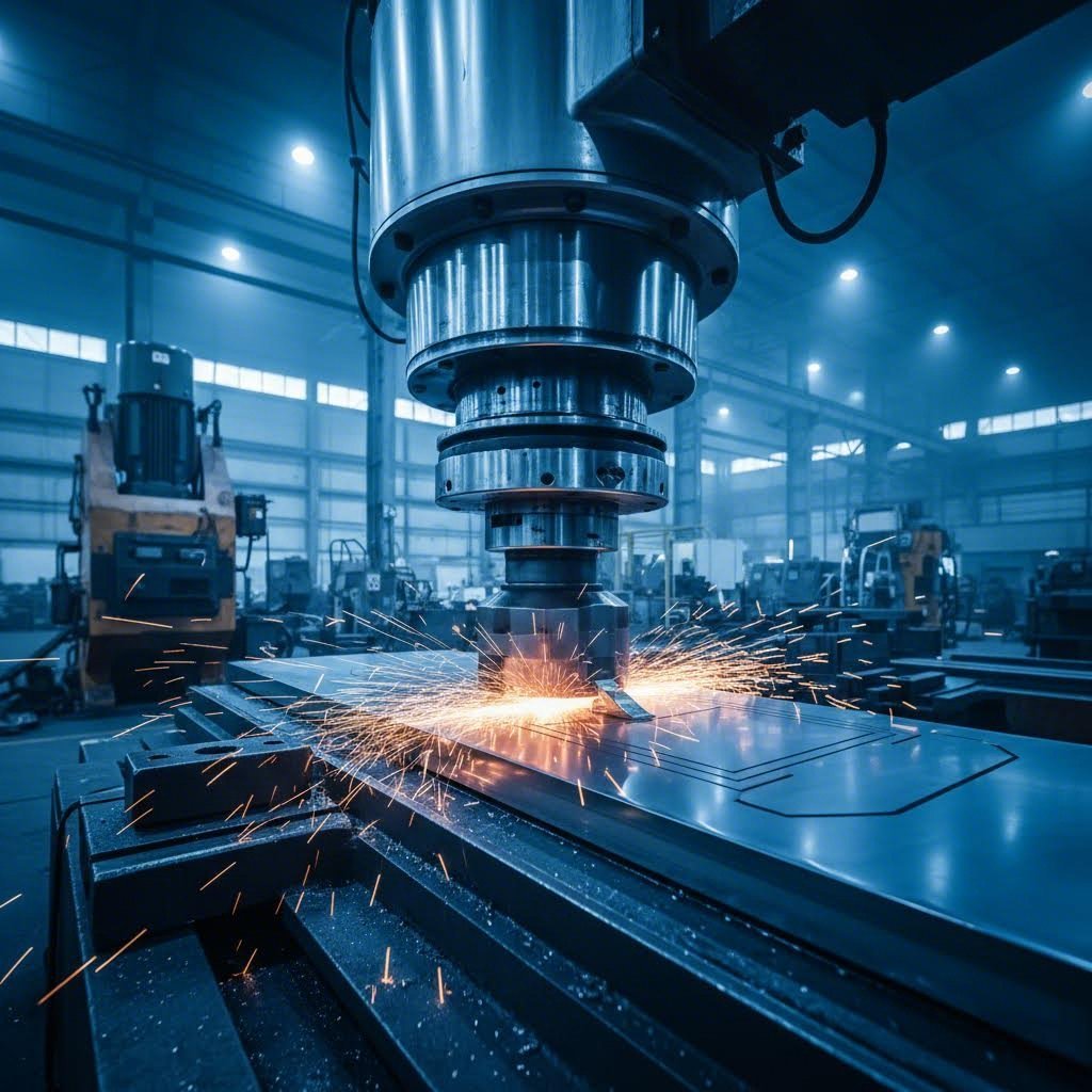
Stamping, also called pressing, is a cold-forming metalworking process that transforms flat sheet metal into specific shapes using dies and stamping presses. Unlike machining operations that remove material, stamping reshapes metal through controlled deformation—making it faster, more efficient, and ideal for high-volume production.
The stamping meaning extends beyond a single action. This process can involve one operation or a carefully orchestrated series of operations—bending, punching, embossing, and more—all working together to create complex components. Understanding this distinction matters because it directly impacts how manufacturers approach part design, tooling investment, and production planning.
From Flat Sheet to Finished Part
Imagine feeding a simple metal sheet into a press and, within seconds, watching it emerge as a precisely shaped automotive bracket or electronic connector. That's the stamping process in action.
Here's how it works: a flat metal blank enters the press, where custom-built dies—essentially hardened steel tools—apply tremendous force. The upper die descends onto the lower die with the metal sandwiched between them. This pressure, combined with the die's geometry, forces the metal to flow and conform to the desired shape permanently.
The definition of stamped parts includes everything from simple flat washers to complex three-dimensional components with multiple bends and features. What makes this transformation remarkable is that no material is removed during the process. The metal simply reshapes, maintaining its structural integrity while taking on new forms.
The Cold-Forming Advantage Explained
Why does stamping means working at room temperature matter so much? Cold forming offers several critical advantages over hot-working processes:
- Superior surface finish – Parts come out smooth without the oxidation or scale that heat causes
- Tighter tolerances – No thermal expansion to account for, meaning more precise dimensions
- Work hardening benefits – The deformation process actually strengthens certain metals
- Energy efficiency – No furnaces or heating equipment required
The physics behind cold forming relies on plastic deformation—pushing metal beyond its elastic limit so it permanently takes the die's shape. When pressure and die geometry work together correctly, the metal flows predictably, creating consistent parts cycle after cycle. This differentiates stamping from subtractive methods like CNC machining, where material is cut away to achieve the final shape.
Why Stamping Dominates High-Volume Production
What is a stamping operation's biggest strength? Speed and repeatability. Modern stamping presses can produce hundreds of parts per minute, each virtually identical to the last. Once the dies are built and the process is dialed in, manufacturers achieve remarkable consistency—sometimes holding tolerances within a few thousandths of an inch.
The economics become compelling at scale. While tooling represents a significant upfront investment, the per-part cost drops dramatically as volume increases. This is why industries like automotive manufacturing—where Henry Ford famously adopted stamping when die forging couldn't keep pace with demand—rely so heavily on this process.
Whether you're producing simple brackets or complex body panels, the stamping process delivers the combination of speed, precision, and cost-effectiveness that modern manufacturing demands.
Core Stamping Operations and Techniques Explained
Now that you understand what stamping is, let's explore the specific operations that make it all happen. Each metal operation in the stamping process serves a distinct purpose—and knowing when to use each one can mean the difference between an efficient production run and costly mistakes.
Think of these operations as your stamping toolbox. Some cut, some shape, some add detail. Master them, and you'll understand how complex parts come together from simple sheets.
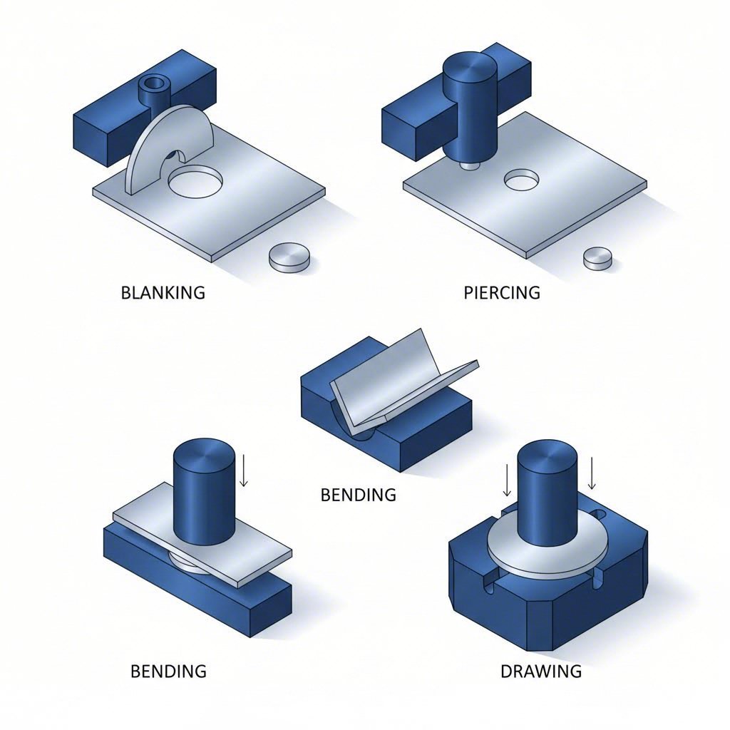
Blanking and Piercing Operations
These two operations often get confused because they both involve cutting—but the distinction matters significantly for your production planning.
Blanking cuts a flat shape from sheet metal where the cut-out piece becomes your finished part (or moves to further processing). When you're blank stamping metal for washers, gear blanks, or decorative components, the surrounding sheet becomes scrap. According to Fox Valley Stamping, blanking is commonly used across automotive, aerospace, and electronics industries for producing discs, gears, and decorative elements.
Piercing (also called punching) does the opposite—it creates holes or cutouts within your workpiece. Here, the punched-out material is scrap, and the remaining sheet is your product. You'll find piercing used extensively for:
- Ventilation holes in enclosures
- Fastener locations in brackets
- Electrical cutouts in control panels
- Complex hole patterns in HVAC components
The key difference? With blanking, you keep what falls out. With piercing, you keep what stays behind. Simple enough, but getting it wrong during die stamping design leads to expensive tooling revisions.
Bending and Forming Fundamentals
When your part needs angles or curves—rather than just flat profiles—bending and forming operations enter the picture.
Bending deforms sheet metal along a straight axis using a stamping press and die combination. A ram applies extreme force against the blank, creating V-shaped, U-shaped, or custom angular configurations. Common bent parts include brackets, chassis components, and enclosures used across electronics, appliances, and automotive applications.
Several bending variations exist:
- Air bending – The die doesn't fully contact the sheet, allowing angle adjustments through clearance control. Lower tonnage required, but tighter tolerances are harder to achieve.
- Bottoming – Strong pressure drives the sheet into a fitted V-shaped die, producing permanent, precise bends with excellent repeatability.
- Flanging – Bends edges at 90 degrees around punched holes, creating smooth rims instead of sharp edges.
Forming reshapes metal without cutting it—creating shallow features like ribs, stiffeners, or decorative trim. Unlike drawing (which we'll cover next), forming doesn't create significant depth. Think of it as adding surface features rather than creating three-dimensional containers.
Drawing and Deep Drawing Techniques
Here's where metal pressing gets truly impressive. Drawing operations pull flat sheet metal into three-dimensional shapes with significant depth.
In standard drawing, a punch forces sheet metal into a die cavity, stretching and flowing the material to match the die's cross-section. This technique produces thin-walled components, automotive body panels, kitchen sinks, and electronic housings.
Deep drawing takes this further—creating parts where depth exceeds the diameter. Imagine producing a beverage can or cylindrical housing where the height-to-width ratio reaches 2:1 or even 3:1. This requires specialized die stamping setups, precise material selection, and often multiple drawing stages to prevent tearing.
When should you choose drawing over forming?
- Use deep drawing when parts require significant depth (cups, boxes, cylindrical housings)
- Use forming for adding shallow features like flanges, ribs, or embossed details
This distinction directly impacts tooling complexity, press tonnage requirements, and production costs—so getting it right during design saves significant headaches later.
Embossing and Coining for Fine Detail
When your parts need raised patterns, logos, lettering, or ultra-precise features, stamps and embossers come into play through embossing and coining operations.
Embossing stamps a single side of the workpiece, creating raised or indented designs. The metal deforms to produce three-dimensional effects—nameplates, branding elements, structural reinforcements, or decorative patterns. Aluminum works particularly well for embossing due to its excellent ductility.
Coining applies high pressure from both sides simultaneously using two matched dies. This cold-forming technique produces exceptionally fine details with minimal material displacement—think currency coins, precision connectors, or medical device components requiring tight tolerances.
The key difference between these operations:
- Embossing – Single-sided pressure, creates raised/recessed designs, moderate precision
- Coining steel or other metals – Double-sided pressure, produces ultra-fine details, surfaces resist impact and abrasion
Coining typically requires higher tonnage presses but delivers superior surface quality and dimensional accuracy—making it ideal for precision components in electronics, medical devices, and consumer products.
Stamping Operations Comparison Guide
Choosing the right operation depends on your part requirements, material, and production goals. This comparison table helps you match operations to applications:
| Operation Name | Description | Typical Applications | Material Thickness Range |
|---|---|---|---|
| Blanking | Cuts flat shapes from sheet; cut-out becomes the part | Washers, discs, gears, decorative components | 0.005" – 0.250" |
| Piercing/Punching | Creates holes or cutouts; remaining sheet is the part | Ventilation holes, fastener locations, electrical cutouts | 0.005" – 0.188" |
| Bending | Deforms metal along a straight axis to create angles | Brackets, chassis, enclosures, frames | 0.010" – 0.375" |
| Forming | Reshapes metal without cutting; adds shallow features | Decorative trim, stiffened panels, ribs | 0.010" – 0.250" |
| Drawing | Pulls metal into 3D shapes with depth | Auto body panels, sinks, electronic housings | 0.015" – 0.125" |
| Deep Drawing | Creates parts where depth exceeds diameter (2:1+ ratio) | Cans, cylindrical housings, cups, tubes | 0.010" – 0.100" |
| Embossing | Single-sided stamping for raised/recessed designs | Nameplates, branding, structural embossments | 0.010" – 0.125" |
| Coining | High-pressure double-sided stamping for fine detail | Connectors, precision washers, decorative parts | 0.005" – 0.062" |
Understanding these core operations provides the foundation for evaluating more complex stamping approaches. But how do manufacturers combine these operations efficiently for high-volume production? That's where different die types come into play—each offering distinct advantages depending on part complexity and production requirements.
Progressive vs Transfer vs Compound Die Stamping
You've got your stamping operations down—blanking, piercing, bending, drawing. But here's the question that separates efficient production from costly trial-and-error: which die type should you use to combine these operations?
The answer depends on your part complexity, production volume, and budget. Let's break down the three main stamping machinery approaches so you can make informed decisions for your next project.
Progressive Die Stamping for Continuous Production
Imagine a single strip of metal entering a press and emerging as finished parts—hundreds per minute—without ever being handled between operations. That's progressive die and stamping in action.
Progressive dies consist of multiple stations arranged in sequence, each performing a specific operation as the metal strip advances through the press. The strip stays connected throughout the process, with each stroke of the press moving it forward one station while simultaneously performing operations at every station. According to Durex Inc., this setup enables high efficiency and ensures uniformity across all produced components.
Here's what makes progressive dies exceptional for high-volume production:
- Speed – Multiple operations occur simultaneously with each press stroke
- Consistency – Parts remain in registration throughout the process, ensuring tight tolerances
- Automation-friendly – Minimal part handling between operations reduces labor costs
- Scalability – Once running, these dies can produce millions of identical parts
The tradeoff? Progressive dies demand higher upfront design and tooling costs. Their intricate structure requires meticulous planning and precision engineering. However, as Larson Tool notes, the cost per part decreases significantly with large production runs—making this option highly cost-effective for long-term projects.
Best applications include automotive brackets and clips, electronic connectors, and any small-to-medium parts produced in quantities exceeding 50,000 units.
Transfer Die Systems for Complex Geometries
What happens when your part is too large to stay connected to a strip—or requires operations that progressive dies simply can't accommodate? Transfer dies step in.
Unlike progressive systems where parts remain attached to the strip, transfer dies use mechanical transfer systems to move individual workpieces between stations. Each station performs its designated operation, then transfers the part to the next station for further processing.
This independence offers significant advantages for stamping presses handling complex assemblies:
- Larger part capability – No size constraints from strip width limitations
- Complex 3D geometries – Parts can be flipped, rotated, or repositioned between stations
- Deep drawing integration – Multiple draw operations with re-positioning between stages
- Assembly operations – Some transfer systems incorporate welding, fastening, or insertion steps
Transfer dies involve higher tooling and setup costs due to their sophisticated transfer mechanisms. They're best suited for medium to high production runs where the versatility and capability to handle complex parts justify the investment. Industries like aerospace and heavy machinery rely heavily on this stamping technology for producing large structural components.
The controlled transfer processes maintain high accuracy, ensuring each component meets stringent quality standards—critical when you're manufacturing safety-critical parts.
Compound Dies for Simultaneous Operations
Sometimes, simpler is better. Compound dies perform multiple operations—typically cutting and punching—in a single stroke of the press.
Rather than moving through sequential stations, the workpiece experiences all operations simultaneously. The die design combines cutting and forming elements so that one press stroke completes the part. This integration significantly reduces production time and enhances productivity by eliminating multiple handling steps.
Compound dies shine in specific scenarios:
- Flat parts with internal features – Washers with center holes, brackets with mounting cutouts
- Lower volume production – When progressive die investment isn't justified
- Simpler geometries – Parts without complex bends or deep draws
- Quick turnaround projects – Faster die design and build times
Metal stamping presses running compound dies typically produce parts with excellent edge quality and concentricity since all operations occur in a single aligned stroke. The simpler die structure also means less maintenance—regular inspection of cutting and punching components ensures continued accuracy and longevity.
The limitation? Compound dies aren't suitable for complex 3D parts or extremely high volumes where progressive dies would deliver better per-part economics.
Matching Die Type to Production Requirements
Choosing the right die type isn't just about part geometry—it's about balancing upfront investment against long-term production costs. Use this decision framework to guide your selection:
| Criteria | Progressive Die | Transfer Die | Compound Die |
|---|---|---|---|
| Part Complexity | Medium to high (multiple features) | High (large, 3D, multi-stage draws) | Low to medium (flat with cutouts) |
| Production Volume Suitability | High volume (50,000+ parts) | Medium to high volume (10,000+) | Low to medium volume (1,000–50,000) |
| Tooling Cost | High (complex multi-station design) | Highest (transfer mechanisms + dies) | Lowest (simpler single-station design) |
| Cycle Time | Fastest (all stations operate per stroke) | Moderate (transfer time between stations) | Fast (single stroke completion) |
| Best Applications | Small connectors, brackets, clips, electronic components | Large panels, deep-drawn housings, aerospace structures | Washers, simple brackets, flat components with holes |
When evaluating stamping machines for your project, consider this practical guidance:
- Choose progressive dies when you need speed, high volume, and can amortize tooling costs over large production runs
- Choose transfer dies when part size or complexity exceeds strip-based limitations, or when multiple deep drawing stages are required
- Choose compound dies when tooling budget is constrained, volumes are moderate, and parts remain relatively simple
The die type decision directly impacts your equipment requirements too. Progressive and compound dies typically run on standard stamping presses, while transfer die systems require specialized presses with integrated transfer mechanisms—adding to capital equipment considerations.
Understanding these distinctions helps you communicate effectively with stamping partners and make informed decisions about tooling investments. But die selection is only part of the equation—the press itself plays an equally critical role in achieving quality results.
Stamping Press Types and Selection Criteria
So you've selected the right die type for your part—but what about the press itself? The metal stamping press you choose determines how fast you can run, how much force you can apply, and how precisely you can control the forming process.
Think of it this way: your die is the recipe, but the press is the oven. Even the best recipe fails with the wrong equipment. Let's explore the three main press types and how to match them to your production requirements.
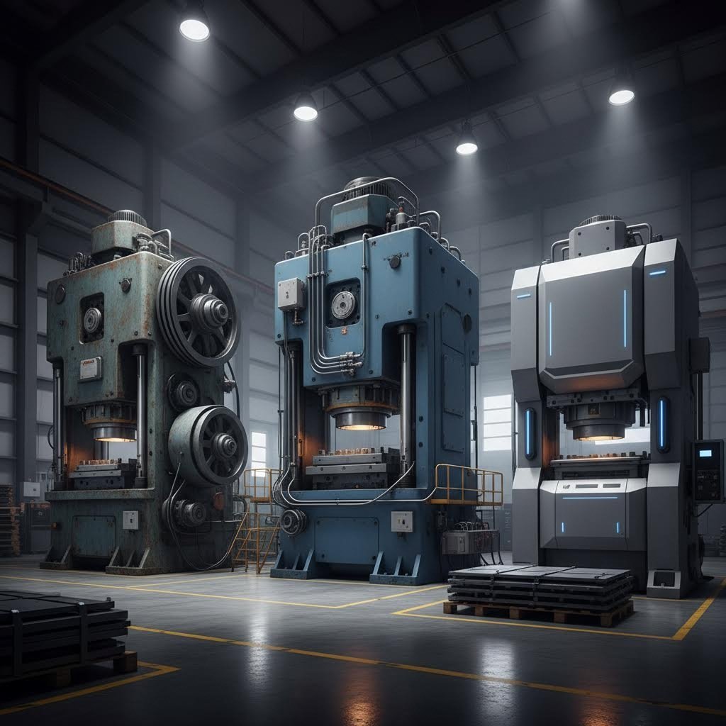
Mechanical Press Speed and Efficiency
When production speed is your priority, mechanical presses deliver. These machines use a flywheel to store rotational energy, releasing it through a crankshaft or eccentric gear mechanism to drive the ram downward with tremendous force.
Here's what makes a mechanical metal stamping machine the workhorse of high-volume production:
- Stroke rates – Capable of 20 to over 1,500 strokes per minute depending on size and configuration
- Fixed stroke length – The ram travels a predetermined distance with each cycle, ensuring consistency
- Tonnage range – Typically 20 to 6,000+ tons, with most production presses falling between 100-1,500 tons
- Energy efficiency at speed – Flywheel momentum reduces energy consumption during continuous operation
According to San Giacomo Presses, mechanical presses achieve their stamping action through energy stored and released from the flywheel—making them better suited for higher-volume production environments where consistent cycling matters more than variable force control.
The tradeoff? Mechanical presses deliver maximum force only at a specific point in the stroke (bottom dead center). This limits flexibility when working with operations requiring sustained pressure throughout the forming process. They're ideal for blanking, piercing, and shallow forming—but struggle with deep drawing applications.
Hydraulic Press Force Control Advantages
What if your parts require sustained pressure throughout the entire stroke? Or you're working with high-strength materials that demand precise force control? Hydraulic presses answer these challenges.
Instead of mechanical linkages, hydraulic presses use cylinders filled with pressurized fluid to generate force. This fundamental difference creates several unique advantages for a steel stamping machine handling demanding applications:
- Full tonnage anywhere in stroke – Unlike mechanical presses, hydraulics deliver maximum force at any point during ram travel
- Variable speed control – Operators can adjust approach speed, working speed, and return speed independently
- Tonnage capacity – Ranges from 20 to 10,000+ tons for heavy-duty applications
- Stroke flexibility – Adjustable stroke length adapts to different part depths without mechanical changes
- Dwell capability – The ram can hold position under pressure—critical for certain forming operations
As Eigen Engineering notes, hydraulic presses are slower than other varieties, but they offer consistency and adaptability that proves invaluable when producing complicated stamped metal parts.
The steel press excels in deep drawing applications where material needs time to flow into die cavities. Complex automotive panels, kitchen sinks, and cylindrical housings often require hydraulic systems that maintain pressure as the metal gradually takes shape.
Servo-Driven Press Programmability
Imagine combining mechanical press speed with hydraulic press flexibility—then adding programmable intelligence. That's the servo press advantage.
Servo-driven metal stamping machines use advanced servo motors to control ram motion directly. Unlike mechanical presses with fixed stroke profiles or hydraulics with fluid-based limitations, servo presses offer complete programmability over the entire forming cycle.
What does programmable motion mean in practice?
- Customizable stroke profiles – Program different speeds and dwell times at various points in the stroke
- Precision positioning – Achieve accuracy within 0.001" throughout the stroke
- Energy regeneration – Servo motors recover energy during the return stroke, reducing overall consumption by 30-50%
- Quick changeover – Store and recall motion profiles for different parts without mechanical adjustments
- Reduced noise – Smoother motion profiles eliminate the impact noise common in mechanical presses
According to industry data, metal stamping press machine technology has evolved dramatically since servo presses entered manufacturing in the early 21st century. These machines excel at precision work—electronics, medical devices, and high-end automotive components where quality trumps raw speed.
The consideration? Servo presses typically carry higher upfront costs than comparable mechanical systems. However, energy savings, reduced die wear, and quality improvements often justify the investment for operations requiring precision or frequently changing production runs.
Calculating Required Press Tonnage
Selecting the right press type is only half the equation. You also need sufficient tonnage—the force capacity—to complete your stamping operations successfully.
Press tonnage requirements depend on several factors:
- Material type and thickness – Higher strength materials and thicker gauges require more force
- Operation type – Blanking requires different force than drawing or forming
- Part perimeter or area – Larger cutting lengths or forming areas increase tonnage needs
- Safety factor – Industry practice adds 20-30% above calculated requirements
For blanking and piercing operations, use this formula:
Tonnage = (Perimeter × Material Thickness × Shear Strength) ÷ 2000
For example, blanking a 4" diameter circle from 0.060" thick mild steel (shear strength ~50,000 psi):
- Perimeter = π × 4" = 12.57"
- Tonnage = (12.57 × 0.060 × 50,000) ÷ 2000 = 18.9 tons
- With 25% safety factor = approximately 24 tons required
Drawing operations require different calculations based on blank diameter, punch diameter, and material properties. Complex parts often need simulation software to accurately predict tonnage requirements—especially when multiple operations occur simultaneously.
When evaluating metal stamping machines for your facility, always verify tonnage capacity exceeds your calculated requirements. Running a press at or near maximum capacity accelerates wear and reduces precision—while undersized equipment simply won't complete the forming operation.
Understanding press capabilities helps you match equipment to applications effectively. But the press and die are only part of the equation—the material you're forming plays an equally critical role in achieving quality results.
Material Selection Guide for Stamping Applications
You've got the right press, the right die type, and a solid understanding of stamping operations. But here's a question that can make or break your project: which metal for stamping should you actually use?
Material selection isn't about choosing the most expensive option—it's about matching material properties to your specific application. The wrong choice leads to cracking, excessive springback, or parts that fail in service. The right choice? Smooth production runs and parts that perform exactly as designed.
Let's explore how different metal stamping materials behave during forming—and when to use each one.
Steel Grade Selection for Structural Parts
Carbon steel remains the workhorse of metal stamping. It's affordable, widely available, and offers an excellent balance between formability and strength. But not all steel grades are created equal.
When selecting steel for stamping, you're navigating a fundamental tradeoff: formability versus strength. Low-carbon steels (like 1008 or 1010) bend and draw easily but offer modest tensile strength. Higher-carbon grades provide better structural performance but resist deformation—increasing the risk of cracking during aggressive forming.
Here's how different carbon steel grades perform:
- Low-carbon steel (0.05-0.15% carbon) – Excellent ductility, ideal for deep drawing and complex bends. Common in automotive brackets and appliance housings.
- Medium-carbon steel (0.25-0.50% carbon) – Balanced strength and formability. Suitable for structural components requiring moderate forming.
- High-strength low-alloy (HSLA) steels – Enhanced strength with acceptable formability. Used in automotive safety structures where weight reduction matters.
Galvanized steel deserves special mention. According to Tenral's material guide, galvanized coatings (≥8μm thickness) provide basic rust prevention while maintaining the carbon steel base's formability—making it ideal for cost-sensitive structural parts like vehicle chassis brackets and appliance panels.
Aluminum Stamping Challenges and Solutions
When lightweight design matters, aluminum stamping becomes the go-to solution. Stamped aluminum parts weigh roughly one-third of equivalent steel components—a significant advantage for automotive, aerospace, and consumer electronics applications.
But the aluminum stamping process presents unique challenges that catch inexperienced manufacturers off guard:
- Springback – Aluminum's lower modulus of elasticity means parts "spring back" toward their original shape after forming. Dies must be designed to over-bend, compensating for this elastic recovery.
- Galling tendency – Aluminum can stick to tooling surfaces, causing surface defects. Proper lubrication and die coatings are essential.
- Strain hardening – Unlike steel, aluminum work-hardens rapidly. Complex parts may require intermediate annealing between forming stages.
Despite these challenges, aluminium stamping parts offer compelling benefits. The 6061-T6 alloy, for example, delivers excellent thermal conductivity (ideal for heat sinks), good corrosion resistance, and acceptable formability for moderate draws and bends. One communications company achieved 25% better heat dissipation and 18% lower production costs by switching from copper to aluminum alloy for 5G base station heat sinks.
For lightweight applications requiring precision, aluminum alloys remain unmatched—provided you account for their unique forming characteristics during die design.
Stainless Steel Work Hardening Behavior
Stainless steel metal stamping demands careful attention to work hardening—the phenomenon where metal becomes stronger and harder as it deforms. Get this wrong, and your parts crack mid-production. Get it right, and you'll produce corrosion-resistant components that outlast alternatives by years.
The key lies in understanding how nickel content affects work hardening rate. As Ulbrich's technical guide explains:
- Type 301 (6-8% nickel) – High work hardening rate. Gains significant strength during forming, making it excellent for bending operations where final part strength matters. However, it's more prone to cracking during deep draws.
- Type 304 (8-10.5% nickel) – Moderate work hardening. Offers good balance between formability and strength. The most commonly specified grade for general stainless steel stamping applications.
- Type 305 (10-13% nickel) – Low work hardening rate. Ideal for deep drawing and coining operations where material needs to flow without rapid strength increases.
Grain structure also impacts stainless steel stamping success. Coarse grains create "orange peel" surface defects during drawing—an undesirable texture resembling citrus skin. Finer grain structures improve both surface finish and ductility.
With tensile strength ≥515 MPa and salt spray resistance ≥48 hours, 304 stainless steel remains the standard for medical equipment housings, food processing components, and new energy vehicle charging terminals where corrosion resistance is non-negotiable.
Copper and Brass for Electrical Components
When electrical conductivity drives your design, copper and brass alloys deliver unmatched performance. These materials flow beautifully during stamping operations while providing the electrical and thermal properties that electronics demand.
Copper offers conductivity up to 98%—making it essential for electrical contacts, connectors, and terminals. Its excellent ductility allows punching into micro-contacts for smartphone SIM card shrapnels and industrial sensor terminals. The tradeoff? Copper is relatively expensive and softer than steel alternatives.
Brass (copper-zinc alloy) provides a cost-effective alternative with excellent machinability. H62 brass, with hardness ≥HB80, stamps cleanly without requiring secondary processing—reducing production costs for high-volume components. Common applications include:
- Smart lock cylinder components
- Automotive air conditioning joints
- Decorative hardware
- Plumbing fittings
According to industry case studies, brass can replace pure copper in many applications where maximum conductivity isn't critical—delivering 22% lower processing costs while maintaining acceptable electrical performance.
Both materials excel in forming operations due to their inherent ductility. Progressive die stamping works particularly well with copper and brass, as their malleability allows continuous high-speed production without the brittleness issues common in harder materials.
Material Properties That Affect Stampability
Regardless of which metal you choose, four material properties determine stamping success:
- Ductility – How much the material can stretch before fracturing. Higher ductility enables deep draws and complex bends.
- Yield strength – The stress at which permanent deformation begins. Lower yield strength means easier forming but potentially weaker final parts.
- Work hardening rate – How quickly the material strengthens during deformation. Low rates favor drawing; high rates favor bending where final strength matters.
- Grain structure – Finer grains generally improve formability and surface finish. Coarse grains can cause surface defects and reduce ductility.
Understanding these properties helps you predict how materials will behave during stamping—and avoid costly production failures.
Metal Stamping Materials Comparison
This comparison table summarizes key characteristics to guide your material selection:
| Material Type | Formability Rating | Typical Applications | Special Considerations |
|---|---|---|---|
| Low-Carbon Steel | Excellent | Automotive brackets, appliance housings, deep-drawn components | Requires corrosion protection; most cost-effective option |
| Galvanized Steel | Good | Chassis brackets, HVAC panels, outdoor enclosures | Coating may crack during severe bending; basic rust prevention |
| Aluminum Alloys | Good to Excellent | Heat sinks, electronics housings, lightweight structural parts | Significant springback; requires lubrication to prevent galling |
| 304 Stainless Steel | Moderate | Medical equipment, food processing, charging terminals | Work hardens during forming; requires higher tonnage |
| 305 Stainless Steel | Good | Deep-drawn containers, complex formed parts | Low work hardening rate ideal for drawing operations |
| Copper | Excellent | Electrical contacts, connectors, thermal components | Highest conductivity but higher cost; soft material |
| Brass (H62) | Excellent | Lock components, plumbing fittings, decorative hardware | Cost-effective alternative to copper; excellent machinability |
Selecting the right material is only one piece of the puzzle. How you design your part and structure your production workflow determines whether that material choice translates into successful, cost-effective manufacturing.
The Complete Stamping Workflow from Design to Production
You've selected the ideal material for your application. But what happens next? How does a concept on paper become a precision stamping part rolling off the production line?
The sheet metal stamping process involves far more than just pressing metal through a die. Success requires a structured workflow where each phase builds upon the previous—from initial design decisions that impact tooling complexity to quality inspection protocols that ensure every part meets specification.
Let's walk through the complete journey from design to finished stamped sheet metal components.
Design for Manufacturability Principles
Here's a reality check: roughly 70% of manufacturing costs are locked in during the design phase. The decisions you make on paper directly determine tooling complexity, production efficiency, and ultimately, your cost per part.
Effective sheet metal design guidelines focus on making parts that stamping equipment can actually produce—consistently and economically. According to Five Flute's DFM guide, mechanical engineers should approach sheet metal stamping design with a first-principles understanding of how forming operations impact final part geometry.
Critical DFM considerations include:
- Minimum bend radii – Keep bend radius greater than or equal to material thickness for ductile materials. For hardened aluminum like 6061-T6, increase this to 4x material thickness to prevent cracking.
- Hole placement – Position holes at least 2x material thickness from edges to prevent bulging. Place holes 2.5x thickness plus bend radius away from bend lines to avoid distortion.
- Grain direction alignment – Orient bends perpendicular to the material's rolling direction when possible. Failure to do so can result in cracking, especially with less ductile metals.
- Bend relief – Add material cutouts where bends meet flat sections to prevent tearing. Aim for relief width greater than half the material thickness.
According to Xometry's stamping design standards, minimum hole diameters depend on material type—1.2x thickness for ductile materials like aluminum, but 2x thickness for higher-strength stainless steel alloys.
These constraints might seem restrictive, but they're actually liberating. Following sheet metal design guidelines upfront eliminates costly redesigns later—and ensures your parts can be manufactured at the tolerances you need.
Tooling Development and Validation
Once your design passes DFM review, tooling development begins. This phase transforms your part geometry into the precision dies that will form every component.
The tooling development process typically follows these stages:
- Die design engineering – Engineers translate part geometry into die station layouts, specifying punch and die clearances, material flow paths, and forming sequences. CAE simulation software predicts material behavior and identifies potential defects before cutting steel.
- Tool steel selection and machining – Die components are manufactured from hardened tool steels capable of withstanding millions of forming cycles. CNC machining and wire EDM create the precise geometries required for consistent part production.
- Die assembly and tryout – Assembled dies undergo initial testing to verify proper material flow, clearances, and part dimensions. Adjustments are made to optimize forming conditions.
- Sample production and validation – Initial parts are measured against specifications. Dimensional data confirms the die produces parts within tolerance before full production begins.
As Die-Matic notes, tooling is pivotal to an efficient, precise, and successful manufacturing process. Choosing the right dies and collaborating with design engineers during the prototype phase proves out the intended process before committing to production tooling.
This validation phase catches problems early—when changes cost hundreds of dollars rather than tens of thousands.
Production Setup and First Article Inspection
With validated tooling in hand, production setup transforms your manufacturing cell from idle equipment into a precision production system.
The sheet metal process setup involves:
- Die installation and alignment – Dies are mounted in the press with precise positioning. Proper alignment ensures consistent forming across all stations and prevents premature tooling wear.
- Material loading and feed setup – Coil stock or sheet blanks are positioned for proper feeding. Feed mechanisms are calibrated to advance material the correct distance between press strokes.
- Press parameter configuration – Tonnage, stroke speed, and shut height are set according to the validated process parameters. Servo presses may require programming of custom motion profiles.
- First article inspection (FAI) – Initial production parts undergo comprehensive dimensional inspection. Measurements are documented and compared against drawing specifications.
- Process approval – Once FAI confirms parts meet requirements, production proceeds with established monitoring protocols.
First article inspection deserves special emphasis. According to industry best practices, quality control in metal stamping is heavily reliant on characteristics of the raw material such as hardness and thickness—making incoming material verification critical before production begins.
Beyond material verification, FAI typically includes:
- Critical dimension measurements using CMM or optical systems
- Surface finish evaluation
- Hardness testing when specified
- Visual inspection for burrs, cracks, or surface defects
This systematic approach ensures problems are caught before thousands of non-conforming parts are produced.
Achieving Tight Tolerances in Stamped Parts
What tolerances can you actually achieve with precision stamping? This question matters because tolerance capabilities directly impact whether stamping suits your application—or whether you need alternative processes.
Tolerance standards vary by operation type and equipment:
| Operation Type | Standard Tolerance | Precision Tolerance | Key Factors |
|---|---|---|---|
| Blanking/Piercing | ±0.005" (±0.13mm) | ±0.002" (±0.05mm) | Die clearance, material thickness, tooling condition |
| Bending | ±0.5° angular, ±0.010" linear | ±0.25° angular, ±0.005" linear | Springback compensation, material consistency |
| Drawing | ±0.010" (±0.25mm) | ±0.005" (±0.13mm) | Material flow control, blank holder pressure |
| Coining | ±0.002" (±0.05mm) | ±0.001" (±0.025mm) | Press tonnage, die precision, material hardness |
Several factors influence whether you'll achieve standard or precision tolerances:
- Equipment type – Servo presses with programmable motion profiles typically achieve tighter tolerances than mechanical presses operating at maximum speed.
- Tooling quality – Precision-ground dies with tighter clearances produce more accurate parts—but require more frequent maintenance.
- Material consistency – Variations in material thickness or hardness directly impact dimensional outcomes. Specifying tighter material tolerances improves part consistency.
- Process control – Statistical process control (SPC) monitoring catches drift before parts exceed tolerance limits.
For precision stamping parts requiring the tightest tolerances, consider specifying coining operations where high pressure produces exceptionally accurate dimensions. Features across multiple bends typically accumulate tolerance stack-up—so critical dimensions should be referenced from a single datum when possible.
Understanding these tolerance capabilities helps you specify requirements appropriately. Over-tolerancing drives up costs through slower production speeds and increased inspection requirements. Under-tolerancing risks assembly problems or functional failures in service.
The Complete Sheet Metal Stamping Workflow
Bringing it all together, here's the sequential workflow with key considerations at each phase:
- Part design and DFM review – Apply sheet metal design guidelines for bend radii, hole placement, and material selection. Verify manufacturability before tooling investment.
- Tooling quotation and approval – Obtain tooling quotes based on production volume, part complexity, and tolerance requirements. Approve die design concepts.
- Die design and CAE simulation – Engineers develop detailed die designs with forming simulations to predict material behavior and optimize station layouts.
- Tool fabrication – Die components are machined, heat-treated, and assembled. Lead times typically range from 4-12 weeks depending on complexity.
- Die tryout and adjustment – Initial samples are produced and measured. Dies are adjusted to achieve target dimensions and surface quality.
- First article inspection and approval – Comprehensive inspection documents confirm parts meet specifications. Customer approval authorizes production.
- Production ramp-up – Process parameters are locked, and production begins with established quality monitoring protocols.
- Ongoing quality control – SPC monitoring, periodic inspections, and die maintenance ensure consistent quality throughout production runs.
This structured approach transforms sheet metal stamping from an art into a repeatable science—where quality is designed in rather than inspected out.
But even with the best workflow, things can go wrong. Understanding common defects and how to prevent them keeps your production running smoothly—and your customers satisfied.
Quality Control and Defect Prevention Strategies
Even with a perfectly designed workflow, stamped parts can still go wrong. Cracks appear where they shouldn't. Edges come out rough. Parts spring back to the wrong angle after forming. Sound familiar?
The difference between a profitable stamping operation and a costly one often comes down to understanding why defects happen—and preventing them before they occur. Let's explore the most common issues affecting stamped metal components and the strategies that keep production running smoothly.
Springback Prediction and Compensation
Here's a frustrating reality: every bent metal part wants to unbend itself. This elastic recovery—called springback—occurs because metal retains some elastic strain after forming. When the press releases, the part partially returns toward its original flat shape.
Springback becomes especially problematic with:
- High-strength materials – Advanced high-strength steels and aluminum alloys exhibit greater elastic recovery than mild steel
- Large bend radii – Gentler bends store more elastic energy, increasing springback
- Thinner materials – Less material to resist the elastic recovery forces
How do manufacturers compensate? Steel stamping dies are designed to over-bend parts beyond the target angle. When springback occurs, the part relaxes into the correct final position. For precision applications, CAE simulation software predicts springback behavior during die design—allowing engineers to calculate exact compensation angles before cutting any tool steel.
Modern servo presses add another layer of control. Programmable dwell times at the bottom of the stroke allow material to "set" before release, reducing elastic recovery. This approach proves particularly effective for stamped steel components requiring tight angular tolerances.
Preventing Wrinkling and Tearing Defects
Wrinkling and tearing represent opposite failure modes—yet they often share the same root cause: improper material flow control.
Wrinkling occurs when sheet metal buckles under compressive stress during drawing operations. Imagine pushing a tablecloth into a bowl—without proper constraint, it bunches up. In stamping, this happens when blank holder pressure is too low or die geometry allows unsupported compression.
Tearing (also called splitting) happens when material stretches beyond its limits. According to Stamping Simulation research, splits result from localized necking where material thins beyond safe limits—particularly common with complicated geometry and high-strength materials.
The causes and solutions for each defect type:
- Wrinkling causes – Insufficient blank holder pressure, excessive material in draw areas, improper die clearance
- Wrinkling prevention – Increase blank holder force, optimize blank size and shape, add draw beads to control material flow
- Tearing causes – Excessive blank holder pressure restricting flow, unsuitable material properties, incorrect blank dimensions, rust or damage on tooling surfaces
- Tearing prevention – Reduce blank holder pressure, select materials with larger yield-to-tensile strength ranges, verify blank geometry through simulation, maintain tooling surfaces
Notice the paradox? Too little blank holder pressure causes wrinkling. Too much causes tearing. Finding the sweet spot requires understanding your specific material and geometry—which is why simulation proves invaluable for complex stamped parts.
Burr Control and Edge Quality
Burrs—those raised edges left after blanking or piercing—might seem like minor annoyances. But they create real problems: assembly interference, safety hazards for handlers, and accelerated wear on mating components.
Burr formation depends on several factors:
- Die clearance – Excessive clearance allows material to flow into gaps rather than shearing cleanly
- Tool sharpness – Worn cutting edges roll material rather than cutting it
- Material properties – Ductile materials tend to form larger burrs than harder grades
- Punch-die alignment – Misalignment creates uneven loading and irregular burr formation
Prevention strategies focus on tooling maintenance and proper design. Optimal die clearance typically ranges from 5-10% of material thickness for steel—tighter clearances produce cleaner edges but accelerate die wear. Regular inspection of cutting edges catches wear before burrs become problematic.
For applications requiring burr-free edges, secondary operations like tumbling, vibratory finishing, or precision deburring may be necessary. However, these add cost—making proper die design and maintenance the preferred approach for stamping design optimization.
Die Maintenance for Consistent Quality
Your dies are precision instruments—and like any precision tool, they wear. Understanding how tooling wear affects stamped metal quality helps you plan maintenance schedules that prevent defects rather than react to them.
Tooling wear manifests in predictable ways:
- Cutting edge dulling – Increases burr formation and requires higher press tonnage
- Surface galling – Material pickup on die faces causes scratches and drag marks on parts
- Geometric drift – Wear on forming surfaces gradually changes part dimensions
- Coating breakdown – Protective coatings wear through, accelerating base metal degradation
According to Manor Tool's quality guidance, proper maintenance involves regularly inspecting, lubricating, cleaning, and replacing equipment as necessary. Through consistent maintenance, you expand tool life and minimize the risk of poor-quality stamping.
Effective die maintenance programs include:
- Scheduled inspections based on stroke counts rather than calendar time
- Documented wear measurements tracking dimensional changes over production runs
- Preventive sharpening before cutting edges degrade past recovery points
- Lubricant monitoring to ensure proper film formation between tooling and workpieces
The economics favor prevention. Resharpening a punch costs a fraction of replacing it—and catching wear early prevents the scrap costs associated with out-of-tolerance production.
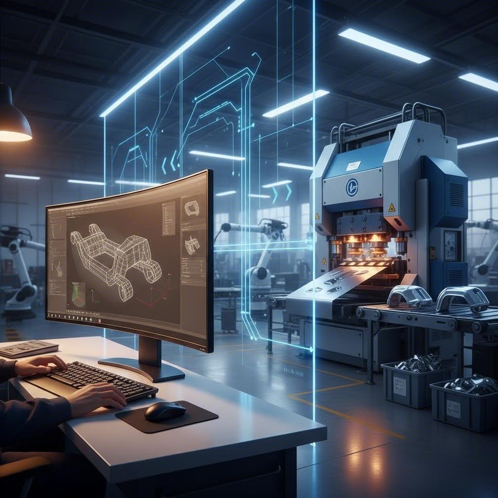
How CAE Simulation Prevents Defects
Why wait until production to discover problems? Modern CAE simulation predicts defects before cutting any tool steel—saving weeks of tryout time and thousands in tooling modifications.
According to CAE simulation research, forming process simulation requires careful setup to ensure realistic results—including accurate material modeling, proper boundary conditions, and appropriate contact and friction definitions.
Simulation identifies potential issues including:
- Thinning zones likely to tear during forming
- Compression areas prone to wrinkling
- Springback magnitude requiring die compensation
- Material flow patterns affecting final part dimensions
The investment in simulation pays dividends throughout production. Dies designed with simulation guidance typically require fewer tryout iterations, achieve target dimensions faster, and produce more consistent parts over extended production runs.
For complex stamped metal components—especially those involving deep drawing or high-strength materials—simulation has become standard practice rather than optional luxury. The question isn't whether you can afford simulation; it's whether you can afford the alternative of discovering problems on the press floor.
Understanding defect prevention keeps your production running efficiently. But how does stamping compare to alternative manufacturing processes—and when should you choose something else entirely?
Stamping vs Alternative Manufacturing Processes
You've mastered the fundamentals of the metal stamping process—operations, die types, press selection, materials, and quality control. But here's the question that determines whether stamping makes sense for your project: when should you choose stamping over other manufacturing methods?
The answer isn't always straightforward. Each manufacturing process excels in specific scenarios, and selecting the wrong one can cost you thousands in unnecessary expenses or missed production deadlines. Let's compare stamping against the three most common alternatives: CNC machining, laser cutting, and 3D printing.
Stamping vs CNC Machining Economics
At their core, stamping and CNC machining represent fundamentally different approaches to creating parts. Stamping reshapes material through forming—no metal is removed. CNC machining removes material through cutting—chips end up in the scrap bin.
This distinction drives significant economic differences:
- Material utilization – Stamping manufacturing typically achieves 85-95% material utilization, while CNC machining may use only 30-60% of raw stock depending on part geometry
- Cycle time – A stamping press produces parts in seconds; CNC machining requires minutes to hours per part
- Tooling investment – Stamping requires custom dies ($10,000-$50,000+), while CNC uses standard cutting tools ($50-$500 each)
- Part complexity – CNC excels at complex 3D geometries from solid stock; stamping works best with sheet metal features
When does CNC machining win? For low-volume production of complex solid parts, CNC's flexibility beats stamping's tooling investment requirement. If you need 50 intricate brackets with tight tolerances on machined features, CNC delivers without the weeks of die development.
When does stamping dominate? Once volumes exceed a few thousand units, the manufacturing stamping process becomes dramatically more economical. The per-part cost drops as tooling amortizes across production—eventually reaching pennies per part for simple geometries.
When Laser Cutting Beats Stamping
Laser cutting and stamping both work with sheet metal—so this comparison gets particularly interesting. Both processes cut flat shapes, create holes, and produce the blanks that become finished parts.
According to industry research, laser cutting delivers 40% cost reduction compared to stamping for batches under 3,000 units by eliminating $15,000+ tooling costs and achieving ±0.1mm precision compared to stamping's ±0.3mm tolerance.
The key advantages of laser cutting include:
- Zero tooling investment – Digital programming eliminates die costs entirely
- Rapid turnaround – Parts can ship within 24-48 hours versus 4-8 weeks for stamping tooling
- Design flexibility – Change part geometry instantly by loading a new cutting program
- Superior precision – Fiber lasers achieve ±0.1mm tolerances consistently
However, production stamping reclaims the advantage at higher volumes. Stamping presses cycle at hundreds of strokes per minute—far faster than even the quickest laser systems. The hidden expenses also shift: laser cutting costs scale linearly with quantity, while stamping costs drop dramatically as volumes increase.
Choose laser cutting when: production volumes stay under 3,000 units, you need rapid prototyping capability, designs change frequently, or precision requirements exceed stamping capabilities.
Choose stamping and pressing when: volumes exceed 10,000 units, part geometry suits forming operations (bends, draws, embosses), and long-term production justifies tooling investment.
Stamping vs Additive Manufacturing Tradeoffs
3D printing (additive manufacturing) has revolutionized prototyping and low-volume production. But how does it compare to production metal stamping for actual manufacturing applications?
The comparison reveals complementary strengths rather than direct competition:
- Prototyping speed – 3D printing produces functional prototypes in hours or days; stamping requires weeks of tooling development first
- Geometric freedom – Additive manufacturing creates complex internal features impossible with stamping
- Material properties – Stamped metal typically offers superior strength, ductility, and surface finish compared to printed metals
- Production economics – 3D printing costs remain relatively flat regardless of quantity; stamping per-part costs plummet at volume
Smart manufacturers use both processes strategically. 3D printing validates designs quickly before committing to stamping tooling. Once designs are finalized and volumes justify the investment, stamping takes over for production.
The crossover point depends on part complexity and size. Simple stamped parts become more economical than 3D printing at quantities as low as 100-500 units. Complex parts with extensive post-processing may not favor stamping until volumes reach several thousand.
Manufacturing Process Comparison Guide
This comparison table provides decision criteria across the most relevant factors for process selection:
| Criteria | Stamping | CNC Machining | Laser Cutting | 3D Printing |
|---|---|---|---|---|
| Setup Cost | High ($10,000-$50,000+ for dies) | Low (standard tooling) | None (digital programming) | None to Low |
| Per-Part Cost (Low Volume) | Very High (tooling amortization) | Moderate to High | Low to Moderate | Moderate to High |
| Per-Part Cost (High Volume) | Very Low (pennies per part) | Remains High | Remains Moderate | Remains High |
| Material Utilization | 85-95% | 30-60% | 70-85% | Near 100% (powder recycling) |
| Geometric Complexity | Moderate (sheet metal features) | High (3D solid parts) | Low to Moderate (2D profiles) | Very High (internal features) |
| Typical Lead Time | 4-8 weeks (tooling) + production | Days to weeks | 24-48 hours | Hours to days |
Making the Right Process Decision
How do you translate this comparison into actionable decisions? Focus on three primary factors:
Volume requirements drive the economics. For production runs exceeding 10,000 units with stable designs, stamping almost always wins on cost. Below 1,000 units, laser cutting or CNC machining typically proves more economical.
Part geometry determines feasibility. Sheet metal parts with bends, draws, and stamped features suit the stamping process naturally. Solid 3D parts requiring machined features need CNC. Flat profiles with complex cutouts favor laser cutting.
Timeline constraints often override cost considerations. Need parts next week? Laser cutting or 3D printing delivers. Have six months for tooling development and long-term production? Stamping's economics become compelling.
The best manufacturers don't commit to a single process—they match each project to the optimal method. Understanding these tradeoffs positions you to make informed decisions that balance cost, quality, and delivery requirements.
With process selection clarified, let's examine how these principles apply in one of stamping's most demanding applications: automotive manufacturing.
Automotive Stamping Applications and Industry Standards
When it comes to the stamping process in manufacturing, no industry pushes the boundaries quite like automotive. Every vehicle rolling off assembly lines contains hundreds—sometimes thousands—of precision metal stamping parts, from massive body panels to tiny electrical connectors. The stakes? A single defective bracket could trigger a million-dollar recall.
So what makes automotive metal stamping so demanding? And how do manufacturers consistently produce millions of stamped metal parts that meet the industry's exacting requirements? Let's explore the applications, standards, and quality systems that define this critical sector.
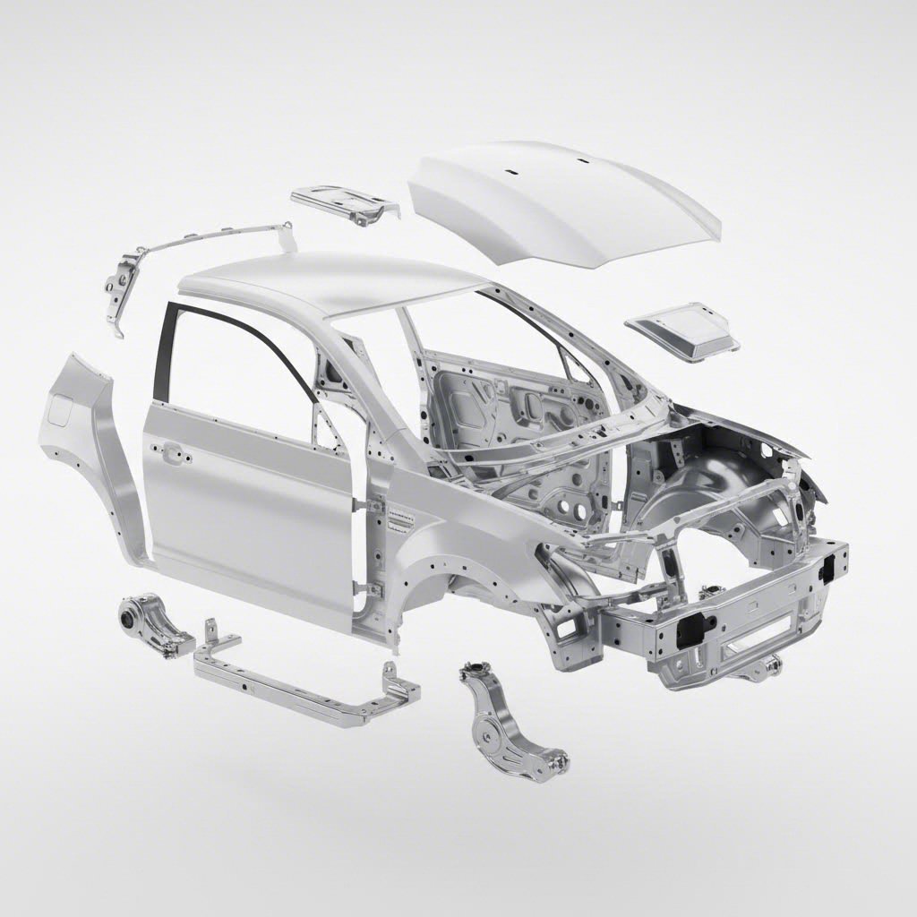
Body Panel and Structural Component Stamping
Walk around any car and you're looking at automotive stamping in action. Doors, hoods, fenders, roofs, trunk lids—these visible body panels all start as flat sheet metal before being transformed through high-volume metal stamping operations.
According to Franklin Fastener's industry research, these components must be durable, lightweight, and precisely shaped. Metal stamping delivers all three requirements efficiently and cost-effectively at the volumes automotive production demands.
Beyond what you see, structural and safety components form the vehicle's backbone:
- Frame rails and cross-members – Provide structural integrity during normal operation and crash events
- Reinforcement brackets – Strengthen critical attachment points throughout the chassis
- Suspension components – Control arms, subframes, and linkages that deliver handling and comfort
- Engine and transmission parts – Cylinder heads, valve covers, oil pans, and housings that withstand extreme temperatures and mechanical stress
The precision metal stamping required for these applications goes far beyond simple forming. Many structural components undergo multiple drawing stages, require tight dimensional tolerances (sometimes as tight as 0.05mm according to Worthy Hardware's technical analysis), and must maintain consistency across production runs spanning millions of units.
Interior and exterior trim components—instrument panel frames, center consoles, door handles, emblems, and grilles—add another layer of complexity. These metal stamped parts require not just dimensional accuracy but excellent surface quality for visible applications.
Meeting Automotive OEM Quality Standards
Here's where automotive stamping diverges dramatically from other industries: the quality management systems required to participate as a supplier.
IATF 16949 certification has become the universal language of automotive quality. Originally drafted in 1999 by the International Automotive Task Force, this certification harmonizes quality assessment systems across the global automotive industry. According to Master Products' certification overview, IATF 16949 creates a baseline for the quality you can expect when contracting automotive metal stamping projects.
The certification focuses on three primary aims:
- Quality and consistency improvement – Standardizing manufacturing processes to ensure every part meets specifications, with added benefits including reduced production costs and long-term sustainability
- Supply chain reliability – Establishing certified suppliers as "suppliers of choice" among leading automotive manufacturers through proven consistency and accountability
- Industry integration – Seamlessly connecting with ISO certification standards to create unified quality management across the supply chain
What does this mean in practice? IATF 16949 demands rigorous process control, complete traceability, and comprehensive risk management—requirements far beyond what typical manufacturing sectors expect. The literature emphasizes prevention of defects and production variances, as well as minimizing scrap and waste.
For stamped metal parts destined for automotive applications, this translates to documented control plans, statistical process monitoring, and validated measurement systems. A bracket failing in consumer electronics is an inconvenience. That same bracket failing in a vehicle's braking system is a disaster—which explains why automotive standards exist in a category of their own.
Certified suppliers like Shaoyi combine IATF 16949 certification with advanced CAE simulation to achieve the defect-free results automotive OEMs demand. This integration of quality systems with predictive engineering represents the current state of the art in precision metal stamping parts production.
High-Volume Automotive Production Requirements
Automotive stamping operates at scales that would overwhelm most manufacturing operations. A single vehicle model might require 300-500 unique metal stamping components. Multiply that by production volumes of 200,000+ vehicles per year, and you begin to understand why efficiency matters so intensely.
The benefits that make automotive metal stamping viable at these volumes include:
- Increased efficiency – Specialized stamping presses and progressive die systems enable rapid manufacture of components, critically boosting production pace while maintaining consistency
- Improved quality – Precision dies designed for automotive applications ensure good surface quality and interchangeability across manufacturing runs
- Enhanced value – High-volume production reduces per-part costs dramatically, making metal stamping one of the most cost-effective processing methods in the industry
- Reduced waste – Optimized blank designs and techniques like fine blanking minimize material waste while creating lightweight parts that improve vehicle fuel efficiency
Meeting these requirements demands more than just capable equipment. Development cycles have compressed dramatically, with OEMs expecting rapid prototyping in as little as 5 days for initial tooling concepts. Modern stamping partners must accelerate development cycles while maintaining the precision that production demands.
First-pass approval rates have become a critical metric. Leading suppliers achieve 93% or higher first-pass approval rates—meaning tooling produces specification-conforming parts on the first production attempt. This capability saves weeks of adjustment time and gets vehicles to market faster.
The combination of CAE simulation during die development, precision manufacturing of stamping dies, and rigorous quality systems creates a framework where high-volume automotive production becomes predictable rather than chaotic. For manufacturers evaluating stamping partners, these capabilities—rapid prototyping, high first-pass rates, and certified quality systems—serve as benchmarks for supplier selection.
Whether you're sourcing body panels, structural brackets, or precision metal stamping parts for electrical systems, understanding automotive industry standards helps you evaluate suppliers and set appropriate expectations for your projects.
Choosing the Right Stamping Approach for Your Project
You've explored the fundamentals of the stamping process in manufacturing—from core operations and die types to material selection and quality control. Now comes the practical question: how do you translate this knowledge into actionable decisions for your specific project?
Whether you're launching a new product or optimizing an existing supply chain, the right approach depends on understanding when stamping makes economic sense, what is metal stamping capable of delivering for your application, and how to identify partners who can execute effectively. Let's break down the decision framework.
Volume Thresholds for Stamping Investment
The economics of metal stamping service hinge on one critical factor: production volume. Unlike processes where costs scale linearly, stamping follows an asymptotic curve—high upfront tooling investment that amortizes across production, driving per-part costs down dramatically as quantities increase.
According to industry cost estimation guidelines, the core formula looks like this:
Total Cost = Fixed Costs (Design + Tooling + Setup) + (Variable Cost/Unit × Volume)
Here's how the math plays out at different volume levels:
- Under 1,000 units – Stamping is typically more expensive than alternatives like laser cutting or CNC machining. Tooling costs ($5,000-$100,000+) can't be spread across enough parts to compete economically.
- 1,000-10,000 units – The crossover zone. Simple parts with basic dies may justify stamping investment. Complex parts often favor alternative processes.
- 10,000-50,000 units – Stamping becomes increasingly attractive. Progressive die investments typically yield the lowest total cost of ownership by drastically reducing cycle times and labor.
- 50,000+ units – Stamping dominates. Per-part costs drop to pennies for simple geometries, with cycle times measured in seconds rather than minutes.
The strategic goal is determining your specific volume threshold—the point where die investment pays off. For automotive projects exceeding 10,000 units annually, investing in complex progressive dies almost always makes sense. For lower volumes, compound dies or simpler tooling approaches may optimize your total spend.
Don't forget the hidden multiplier: die longevity. Quality metal stamping partners guarantee tooling for 1 million strikes or more, effectively capping your tooling spend for the project's lifecycle. This amortization extends your cost advantage across years of production.
Evaluating Stamping Partner Capabilities
Finding the right partner for custom metal stamping involves more than comparing quotes. The lowest piece price is rarely the best value—what matters is total cost of ownership, including quality, reliability, and engineering support.
According to supplier selection best practices, the ideal partner functions as an extension of your team, offering engineering expertise beyond just manufacturing capacity. Use this framework to evaluate potential metal stamping services providers:
Certifications and Quality Systems
- ISO 9001 – Baseline quality management system certification. Essential for any professional operation.
- IATF 16949 – Required for automotive supply chain participation. Indicates rigorous process control and traceability.
- Industry-specific certifications – AS9100 for aerospace, ISO 13485 for medical devices. Match certifications to your application requirements.
Engineering Support and DFM Capabilities
- Design for Manufacturability (DFM) review – Partners who evaluate your designs early can suggest modifications that reduce tooling complexity and production costs.
- CAE simulation – Advanced suppliers use forming simulation to predict and prevent defects before cutting tool steel—saving weeks of tryout time.
- Tooling design expertise – In-house die engineering ensures optimized station layouts and material flow.
Prototyping Speed and Production Capacity
- Rapid prototyping timelines – Look for partners offering prototype tooling in 5-10 days rather than weeks. This accelerates your development cycle significantly.
- First-pass approval rates – Top performers achieve 93% or higher first-pass rates, meaning tooling produces conforming parts on the first attempt.
- Press capacity range – Verify the supplier's tonnage range matches your part requirements. Insufficient capacity limits part size; excessive capacity wastes resources.
- Volume scalability – Ensure the partner can grow with your needs, from initial runs to high-volume production.
Material Expertise and Supply Chain
- Material variety – Experienced suppliers work with multiple materials—steel, aluminum, stainless, copper alloys—and understand how each behaves during forming.
- Supply chain relationships – Strong mill connections ensure material availability, stable pricing, and complete traceability with certifications.
Value-Added Services
- Secondary operations – Heat treating, plating, deburring, and assembly capabilities simplify your supply chain.
- Inventory management – Kanban or just-in-time delivery programs reduce your on-hand stock and improve cash flow.
Partners like Shaoyi exemplify what quality metal stamping looks like in practice—combining IATF 16949 certification with rapid prototyping capabilities (as little as 5 days) and high first-pass approval rates (93%). Their comprehensive mold design and fabrication capabilities demonstrate the engineering depth you should seek when evaluating custom metal stampings suppliers.
Next Steps for Your Stamping Project
Ready to move forward? Here's your action plan for launching a successful stamping project:
- Define your requirements clearly – Document part geometry, material specifications, tolerances, and estimated annual volumes. Include functional requirements and critical-to-quality features.
- Request DFM feedback early – Share designs with potential partners before finalizing. Their input on manufacturability can save significant tooling costs.
- Compare total cost of ownership – Look beyond piece price. Factor in tooling amortization, quality systems, logistics, and engineering support.
- Verify capabilities firsthand – Request facility tours, sample parts, and references from similar projects. Track record matters.
- Plan for scale – Choose partners who can support your growth from prototyping through high-volume production without vendor transitions.
The stamping process in manufacturing offers unmatched efficiency for high-volume metal parts production. With the right approach—appropriate volume thresholds, suitable materials, achievable tolerances, and capable custom metal stamping services partners—you can transform sheet metal into precision components that meet your exact specifications.
Your next project deserves a partner who combines engineering expertise with production capability. Start by evaluating suppliers against the criteria outlined here, and you'll be well-positioned to leverage stamping's full potential for your manufacturing needs.
Frequently Asked Questions About Stamping Process in Manufacturing
1. What are the 7 steps in the stamping method?
The seven most common metal stamping processes include blanking (cutting flat shapes from sheet metal), piercing (creating holes or cutouts), drawing (pulling metal into 3D shapes), bending (creating angular deformation), air bending (using controlled clearance for angle adjustments), bottoming and coining (high-pressure operations for precise details), and pinch trimming (removing excess material). These operations can be performed individually or combined in progressive dies for high-volume production. IATF 16949-certified suppliers like Shaoyi use advanced CAE simulation to optimize these operations for defect-free results.
2. What is the concept of stamping?
Stamping is a cold-forming metalworking process where flat sheet metal is transformed into specific shapes using dies and stamping presses. Unlike machining that removes material, stamping reshapes metal through controlled deformation using pressure and die geometry. This process can involve single operations or multiple sequential steps including blanking, piercing, bending, drawing, embossing, and coining. Stamping dominates high-volume production because modern presses produce hundreds of parts per minute with tolerances as tight as 0.001 inches.
3. What is the cycle time of stamping?
Traditional sheet metal stamping achieves typical cycle times of less than 10 seconds per part, with high-speed mechanical presses capable of 20 to over 1,500 strokes per minute. Cycle time varies based on press type, part complexity, and die configuration. Progressive dies enable the fastest cycles since multiple operations occur simultaneously with each press stroke. Servo-driven presses offer programmable motion profiles that optimize cycle times while maintaining precision, making them ideal for applications requiring both speed and accuracy.
4. How do you choose between progressive, transfer, and compound dies?
Choose progressive dies for high-volume production (50,000+ parts) of small-to-medium components requiring multiple operations. Transfer dies work best for larger parts with complex 3D geometries that cannot stay connected to a strip during processing. Compound dies suit lower volumes (1,000-50,000 units) of simpler flat parts with cutouts. The decision balances tooling cost, cycle time, and part complexity. Leading stamping partners achieve 93% first-pass approval rates through CAE simulation during die development.
5. What materials work best for metal stamping applications?
Low-carbon steel offers excellent formability for deep drawing and complex bends at the lowest cost. Aluminum alloys provide lightweight solutions but require springback compensation. Stainless steel 304 delivers corrosion resistance with moderate formability, while 305 stainless suits deep drawing due to lower work hardening. Copper and brass excel for electrical components with conductivity up to 98%. Material selection depends on balancing formability, strength requirements, and application-specific needs like corrosion resistance or electrical conductivity.