 Small batches, high standards. Our rapid prototyping service makes validation faster and easier —

Reducing Scrap in Metal Stamping: 5 Technical Strategies for Profitability

TL;DR
Reducing scrap in metal stamping is not just a housekeeping task; it is the single most effective lever for increasing profitability, given that raw materials typically account for 50–70% of total part costs. To transform scrap from a sunk cost into a competitive advantage, manufacturers must adopt a trifecta approach: Product Design (DFM), Tooling Optimization (such as advanced nesting and offal recovery), and Process Control (sensor-based monitoring). The primary metric for success is the Material Utilization Ratio (MUR)—the percentage of raw sheet that becomes a finished part.
This guide explores technical strategies to maximize MUR, from implementing "nano joints" for tighter nesting to utilizing "active speed control" sensors that prevent defects in real-time. By moving beyond basic waste disposal to engineered scrap reduction, stamping operations can recover significant margins.
Optimization Strategy 1: Advanced Nesting & Material Utilization
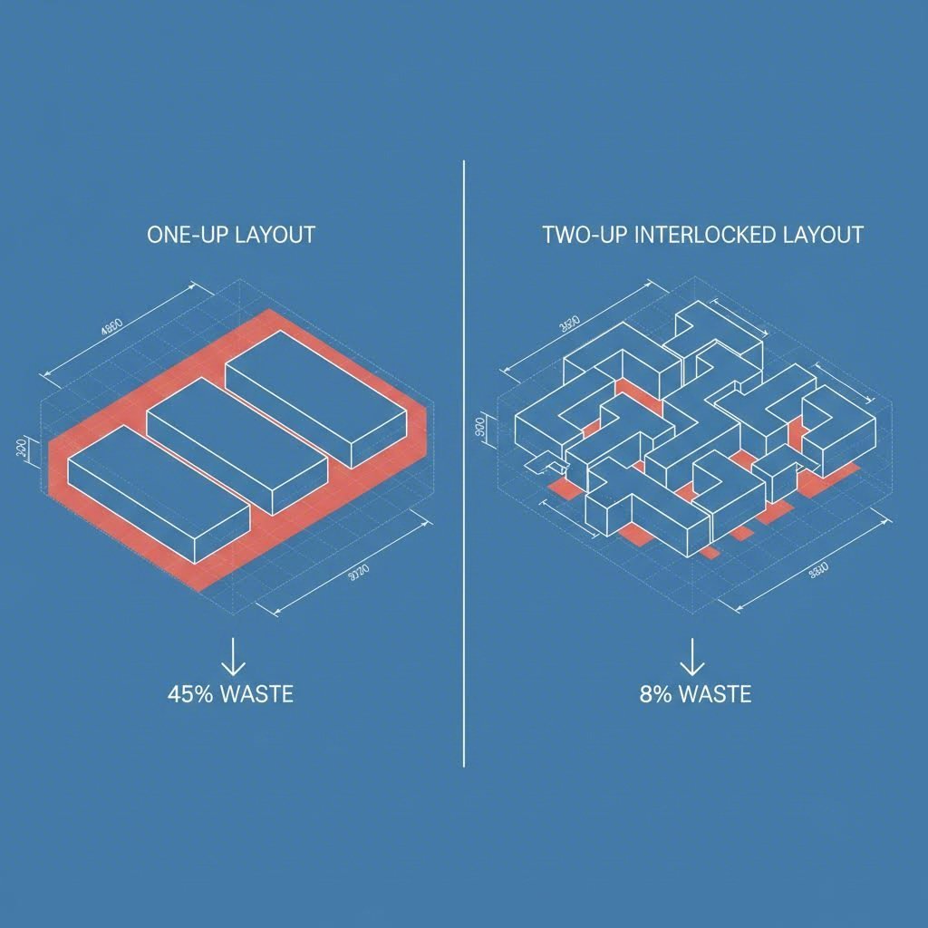
The most immediate opportunity for scrap reduction lies in the engineering of the strip layout. Nesting refers to the practice of arranging parts on a metal strip to minimize the empty space (web) between them. While standard "one-up" layouts are simple to design, they often leave excessive skeleton scrap. Advanced strategies like "two-up" or "interlocked" nesting can increase material utilization by 5–15%, directly impacting the bottom line.
A powerful technique involves true-shape nesting utilizing modern technologies like nano joints. As detailed by industry leaders like TRUMPF, nano joints are tiny retaining tabs that connect the part to the strip, replacing larger traditional micro joints. Because these tabs are minimal, parts can be nested directly adjacent to one another without the risk of banking out or collision. This proximity allows for significantly tighter layouts, reducing the web width required between parts and effectively squeezing more product out of every coil.
Another sophisticated approach is mixed-part nesting, where a smaller, different component is stamped from the scrap area of a larger part. A classic example cited by ESI Engineering Specialties involves a scuba gear manufacturer producing 20,000 D-rings per year. Engineers realized they could stamp a smaller washer-like ring from the inside "D" cutout of the larger ring—material that would otherwise be discarded. This effectively yielded two parts for the material cost of one. However, a critical rule of thumb applies here: the production volume of the larger part must be equal to or greater than that of the smaller nested part to avoid accumulating inventory of unneeded components.
Key Checklist for Strip Layout Reviews
- Bridge Width: Is the web width optimized for the material thickness?
- Grain Direction: Are bends oriented perpendicular to the grain to prevent cracking?
- Part Rotation: Can rotating the part 180 degrees allow for interlocking?
- Mixed Nesting: Is there a smaller part in the BOM that fits in the scrap zone?
Optimization Strategy 2: Die Design & Engineering Solutions
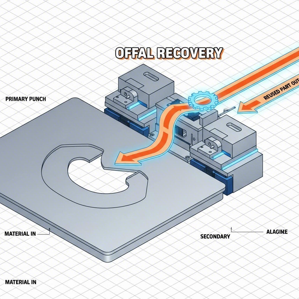
Once the layout is optimized, the focus shifts to the physical tooling. Progressive die design offers unique opportunities to reclaim material through "offal dies" or "recovery dies." An offal die is a secondary tool designed specifically to accept the scrap (offal) generated by a primary operation and stamp a usable part from it. While this adds tooling cost, the long-term savings on high-volume runs often justify the investment.
For continuous production, some stampers employ a technique of "stitching" scrap. As noted in technical discussions by The Fabricator, scrap pieces can sometimes be mechanically fastened together (using toggle locks or similar devices) to create a continuous strip that can be fed into a secondary progressive die. This creative engineering allows for automated feeding of what was previously loose waste. However, engineers must be cautious of work-hardening. Metal that has already been deformed or strained in the first operation may lose ductility, making it unsuitable for deep-drawn secondary parts. It is best suited for simple brackets or flat components.
Validating these complex tooling concepts before committing to hard steel is crucial. This is where partnering with a capability-focused manufacturer becomes essential. Companies like Shaoyi Metal Technology offer comprehensive stamping solutions that bridge the gap from rapid prototyping to mass production. By leveraging their ability to deliver qualified prototypes in as little as five days, engineers can test material flow and nesting feasibility early in the design phase, ensuring that aggressive scrap-reduction strategies are viable for high-volume automotive standards (IATF 16949).
Optimization Strategy 3: Defect Prevention & Process Control
Scrap isn't just about the skeleton left behind; it's also about the parts you throw away. Distinguishing between engineered scrap (offal) and production scrap (defective parts) is vital. While engineered scrap is a design choice, production scrap is a process failure. Common defects such as slug pulling—where a punched slug sticks to the punch face and damages the next part—can ruin thousands of parts if undetected.
To combat this, manufacturers are increasingly adopting in-die sensor technology. Modern systems, such as Active Speed Control highlighted by TRUMPF, use sensors to monitor process radiation and automatically regulate feed rates. If the system detects a potential issue, such as molten material not forming correctly or a slug not ejecting, it can adjust parameters or stop the press immediately. This shifts the paradigm from "inspecting quality out" (sorting bad parts after the fact) to "manufacturing quality in."
Another tool for reducing production scrap is the implementation of Vision Systems and Drop & Cut technology. For remainder sheets—the ends of coils or skeletons that still have usable area—camera systems can overlay part graphics onto the live video feed of the sheet. Operators can then drag-and-drop digital part files onto the remaining material to cut spare parts instantly. This ensures that even the "unusable" tail ends of coils contribute to revenue rather than the recycling bin.
Optimization Strategy 4: Design for Manufacturability (DFM)
The most cost-effective time to reduce scrap is before the die is ever built. Design for Manufacturability (DFM) involves a collaboration between product designers and stamping engineers to adapt component geometry to standard strip widths. Often, a minor change—such as reducing a flange width by 2mm or altering a corner radius—can allow a part to fit on a narrower standard coil or nest more tightly with its neighbor.
Material selection also plays a role. Engineers should evaluate whether a part can be stamped rather than machined. Machining is a subtractive process that turns up to 80% of a block into chips (waste). Stamping, by contrast, is a net-shape process. As noted by ESI, converting a machined component to a stamped one not only drastically reduces material waste but often improves production speed. Furthermore, designers must respect grain direction. Orienting a part on the strip solely for maximum nesting without considering grain direction can lead to cracking during bending, resulting in 100% scrap rates for that batch. A balanced DFM approach weighs material savings against process reliability.
Conclusion: Turning Waste into Profit
Reducing scrap in metal stamping is a multi-disciplinary challenge that rewards precision and creativity. By moving away from the view that scrap is merely a "cost of doing business," manufacturers can uncover significant hidden profits. The integration of advanced nesting strategies like nano joints, the creative reuse of offal through recovery dies, and the deployment of smart sensors creates a robust system where material utilization is maximized.
Success requires a shift in mindset: seeing every square inch of the coil as potential revenue. Whether through minor DFM tweaks that allow for better nesting or investment in smart press controls that prevent thousands of defects, the goal remains the same—maximize the Material Utilization Ratio (MUR) and ensure that the only metal leaving the factory is in the form of quality, sellable parts.
Frequently Asked Questions
1. What is the difference between scrap and waste in metal stamping?
While the terms are often used interchangeably, "scrap" typically refers to recyclable metal (like the skeleton strip or offal) that has some residual monetary value when sold to a dealer. "Waste" or "trash" usually refers to non-recyclable materials or resources that have no recovery value. In a lean manufacturing context, however, any material bought but not sold as a product is considered waste to be minimized.
2. How does part nesting reduce material costs?
Nesting optimizes the layout of parts on the metal strip to minimize the empty space between them. By using techniques like interlocking parts, rotating them, or placing smaller parts in the scrap areas of larger ones, manufacturers can produce more parts per coil. Since material costs often represent 50–70% of the total part cost, increasing parts-per-coil directly lowers the unit cost.
3. What are the most common defects that cause scrap in stamping?
Common defects that lead to rejected parts (production scrap) include slug pulling (where waste material is pulled back into the die), burrs (sharp edges from dull tooling or improper clearance), splitting/cracking (often due to grain direction issues), and wrinkling. Preventing these requires regular die maintenance and process monitoring.
4. What is an offal die or recovery die?
An offal die, also known as a recovery die, is a specialized stamping tool designed to produce a smaller, distinct part using the scrap material (offal) generated from a primary stamping operation. For example, the metal cutout from a car window frame might be fed into an offal die to stamp a small bracket, effectively getting free material for the secondary part.
5. How does grain direction affect scrap rates?
Metal coil has a "grain" similar to wood, created during the rolling process. Bending metal parallel to the grain can cause cracks on the outside of the bend, leading to rejected parts. Designing the strip layout so that critical bends occur perpendicular to or across the grain prevents this cracking, even if it means a slightly less optimized nesting density.