 Small batches, high standards. Our rapid prototyping service makes validation faster and easier —

Stamping Process: 9 Steps To Cut Springback, Scrap, And Cost
Step 1: Define Requirements and Success Criteria for a Streamlined Stamping Process
Clarifying Success: Why the Right Start Matters
When you begin a new stamping process, it’s tempting to jump straight into CAD models or tooling discussions. But imagine running a marathon without knowing the route or finish line—sounds risky, right? The same logic applies here. Before any design or die work starts, you need to map out what success looks like for your stamped part. This step is foundational for every sheet metal process, ensuring all downstream decisions stay aligned and costly surprises are avoided.
Define Critical-To-Quality Features
Start by translating the intended function of your part into a clear list of Critical-To-Quality (CTQ) features. These are the characteristics that, if missed, could cause failures in assembly, sealing, performance, or appearance. For example, if your part mates with others, dimensional accuracy and flatness may be CTQs. If it’s exposed to harsh environments, corrosion resistance or specific coatings might be non-negotiable.
- Function (load-bearing, electrical contact, enclosure, etc.)
- Assembly interfaces and mating surfaces
- Surface finish and appearance
- Regulatory and safety requirements
- Service-life expectations
Safety and regulatory compliance are non-negotiable. Always tie these requirements to specific standards or test methods to avoid ambiguity.
Volume, Budget, and Tooling Amortization Targets
Next, decide your target annual volume and ramp-up profile. Are you producing thousands or millions of parts? This affects your budget, tooling investment, and even which stamping manufacturing process is best suited. Don’t forget to include a placeholder for tooling amortization—spreading the cost of dies across your expected production volume makes per-part costing realistic and avoids budget shocks later.
- Annual production volume and ramp-up plan
- Budget constraints and cost-per-part targets
- Tooling amortization period
Acceptance Criteria and Verification Plan
For each CTQ, assign a measurable tolerance and decide how it will be verified. Avoid over-constraining by only assigning tight tolerances where truly necessary—excessively tight specs can drive up costs or slow down production. Instead, link tolerances to practical measurement methods. For example, if a feature’s flatness is critical for sealing, specify the exact flatness required and how it will be checked (such as with a surface plate or CMM).
- Preliminary tolerances linked to measurement methods
- Material, coating, or joining method constraints
- Design freeze, die buyoff, and PPAP (or equivalent) decision gates
"Ambiguous acceptance criteria are a leading cause of late-stage changes and cost overruns in the stamping process. Clear up front definitions save time and money."
Mapping Requirements to Verification
| Requirement | Verification Method | Responsible Owner |
|---|---|---|
| Dimensional accuracy (±0.05mm) | Caliper/CMM measurement | Quality Engineer |
| Surface roughness (Ra ≤ 3.2μm) | Surface profilometer | Process Engineer |
| Material mechanical properties (σb ≥ 200MPa, σs ≥ 150MPa) | Material certification/Testing | Supplier/Quality |
| Regulatory compliance (e.g., RoHS) | Documentation/Third-party test | Compliance Officer |
Why This Step Reduces Cost and Scrap
By starting with a clear definition of requirements—sometimes called a stamping definition—you’ll notice fewer late-stage design changes and better alignment across engineering, quality, and procurement teams. This approach allows you to avoid overengineering, reduce scrap, and keep costs predictable. It also creates a foundation for the rest of the stamping process in manufacturing, from material selection to die strategy and quality control.
In summary, defining requirements and success criteria at the very beginning sets the tone for the entire stamping manufacturing process. It’s the roadmap that guides every decision, helping you deliver quality stamped parts efficiently and cost-effectively. For a deeper dive into technical requirements and process standards, you can explore detailed guidelines at Keneng Hardware.

Step 2: Select Materials and Plan for Springback in the Stamping Process
Material Selection Matrix: Matching Alloys to Performance and Process
When you’re choosing metal for stamping, it’s easy to get lost in a sea of datasheets and alloy numbers. But imagine you’re building a bridge—you wouldn’t just pick any plank of wood; you’d weigh strength, durability, and how it holds up under stress. The same careful approach applies to the stamping process. For each project, you’ll want to balance formability, springback, corrosion resistance, weldability, and surface finish—making sure your choice fits both the application and the manufacturing method.
| Alloy | Formability | Springback Tendency | Lubricant Compatibility | Finishing Suitability |
|---|---|---|---|---|
| Aluminum 5052 | Excellent for bending and moderate forming | Moderate—requires careful springback compensation | Compatible with standard stamping lubricants | Good for anodizing and painting |
| Stainless Steel 304 | Moderate—higher strength, less ductile than aluminum | Higher springback, especially in thinner gauges | Needs high-performance lubricants | Excellent for polishing; resistant to corrosion |
| Aluminum 6061 | Good for simple bends, less for deep draws | Moderate, but can be managed with proper die design | Standard lubricants; cleaning before finishing is important | Great for powder coating; weldable |
"Always confirm alloy compatibility with your chosen finishing process before locking in material. Some lubricants or coatings may require extra cleaning steps."
Springback Compensation Methods: From Overbend to Die Addenda
Once you’ve shortlisted alloys, springback becomes your next challenge. If you’ve ever bent a paperclip and watched it snap back, you’ve seen springback in action. In the stamping process, springback can cause parts to deviate from their intended shape, especially in aluminium stamping and stainless steel stamping projects. The most common solution is the overbend method—intentionally forming the part further than the final shape so it relaxes into spec once released from the die.
- Overbend/Overcrown: Form the part past the target angle or curve to compensate for elastic recovery.
- Die Addenda Adjustments: Modify die geometry in non-critical areas to direct material flow and reduce springback.
- Draw Beads/Restrike: Add features in the die to restrain or re-form the part, especially for complex contours or stretch flanges.
- Material Selection: Alloys with higher yield strength or certain tempers may exhibit more springback; select accordingly.
For example, in aluminium stamping, the tendency for springback is often moderate, but the right compensation method can make a significant difference in dimensional accuracy. Stainless steel stamping typically requires more aggressive compensation due to higher elastic recovery.
"Springback in stretch flanges can be mitigated by adjusting flanging entry height, intentionally creating compressive forming along the flange to control distortion."
Lubrication and Surface Protection Plan
Don’t overlook lubrication and cleaning. The right lubricant reduces tool wear and prevents galling, especially in high-strength alloys or when running at high speeds. For sheet metal for stamping, always ensure your lubricant is compatible with both the metal and any planned finishing or welding steps. For example, aluminum stamping process parts often require thorough cleaning before anodizing or painting to ensure adhesion and surface quality.
- Choose lubricants tested for your alloy and forming severity.
- Plan cleaning steps before any finishing or joining process.
- Document any special handling for coated or pre-finished materials.
Validation: From Coupon to Pilot Run
- Form test coupons or small strips using your selected alloy and thickness.
- Measure springback and check for defects—adjust compensation if needed.
- Scale up to a pilot run before committing to full die production.
- Review results with your supplier to confirm repeatability.
Choosing the right metal stamping materials and planning for springback early will save you time, scrap, and headaches down the line. With a structured approach, you’ll be ready to move on to designing manufacturable geometry—where DfM rules help stabilize your process and cut out costly trial and error.
Step 3: Apply DfM Rules to Stabilize Geometry in Stamping Design
DfM Checklist for Stampable Geometry
Ever wondered why some stamped parts consistently come out right the first time, while others seem to need endless tweaks? The answer often lies in applying design for manufacturability (DfM) rules early—before you even send your drawing to the shop. By anchoring your stamping design to proven process limits and the realities of your chosen material, you cut down on costly die iterations and avoid the headaches of scrap or rework. Let’s break down the essentials you need for robust sheet metal stamping design.
- Minimum Hole Diameter: At least 1.2x material thickness (for stainless steel, use 2x thickness for better edge quality).
- Edge-to-Hole Spacing: Minimum 2x material thickness from hole to part edge to prevent bulging.
- Hole-to-Hole Spacing: At least 2x material thickness apart to avoid distortion and ensure clean piercing.
- Bend Radius: For ductile materials, inside bend radius ≥ thickness; for harder alloys (like 6061-T6), use 4x thickness.
- Corner Radii: All internal/external corners should have a radius ≥ 0.5x thickness to reduce stress concentrations.
- Bend Relief: Add relief notches at bends near edges—minimum width = material thickness, length = bend radius + thickness.
- Notches and Tabs: Minimum width = 1.5x thickness for durability and tool life.
- Bend Height: Minimum height = 2.5x thickness + bend radius.
- Grain Direction: For high-strength metals, orient bends perpendicular to grain to avoid cracking.
- Trim Reliefs: Pre-plan for progressive dies to protect critical edges and minimize mismatch cuts.
Golden rule: Avoid tight internal corners without reliefs—these are the most common sites for tearing and premature die wear.
Bend Allowance and Springback Templates
When you’re working with a sheet metal die, getting the flat blank to form perfectly into your 3D part isn’t just luck—it’s about using the right bend allowances and factoring in springback. The K-factor, which relates the neutral axis to material thickness, is key here. For most materials, a K-factor between 0.3 and 0.5 is a reliable starting point.
- Bend Allowance: Use standard formulas or supplier data to calculate the arc length for each bend.
- Bend Deduction: Account for material stretch at the outer radius.
- Springback Compensation: For high-strength or hardened alloys, set overbend targets using supplier-recommended factors or trial coupons.
- Validation: Always validate with a first-article run before freezing your sheet metal die design.
Hole, Edge, and Flange Spacing Rules
Spacing rules aren’t just for neatness—they’re your insurance against distortion, bulges, or the need for expensive secondary operations in die stamping. Imagine placing a hole too close to a bend or an edge: you’ll likely see stretching, cracks, or misshapen features. Following spacing guidelines ensures your types of stamping dies perform as intended, whether you’re using progressive, compound, or transfer tooling.
| Feature | Design Rule Reference | Owner | Verified |
|---|---|---|---|
| Hole Diameter | ≥ 1.2x thickness (2x for stainless) | Design Engineer | ☐ |
| Edge-to-Hole | ≥ 2x thickness | Design Engineer | ☐ |
| Bend Radius | ≥ thickness (4x for hard alloys) | Design Engineer | ☐ |
| Corner Radius | ≥ 0.5x thickness | Design Engineer | ☐ |
| Bend Relief | Width ≥ thickness; Length ≥ radius + thickness | Design Engineer | ☐ |
| Notch/Tab Width | ≥ 1.5x thickness | Design Engineer | ☐ |
Integrating these DfM rules into your stamping design review—especially when planning a new sheet metal die—will help you flag potential trouble spots before they hit the shop floor. You’ll reduce scrap, avoid last-minute design changes, and ensure your stamping process flows smoothly into the next stage: selecting the right die strategy and operation sequencing.
Step 4: Select Operations and the Die Strategy for Efficient Metal Stamping
Select Progressive vs Transfer vs Line Dies
When you’re mapping out the forming route for your stamped part, the choice of die strategy is pivotal. Sounds complex? It doesn’t have to be. Imagine you’re building a toolkit—do you need a single tool for everything, or a specialized set for each task? The same logic applies to stamping and pressing operations. Your decision between single-hit, progressive, or transfer dies hinges on part complexity, production rate, and budget.
| Operation | Die Type | Complexity Level | Typical Tolerance Range | Press Features Needed |
|---|---|---|---|---|
| Blanking | Single-hit/Progressive | Low | ±0.1–0.2 mm | Standard stamping presses |
| Piercing | Progressive/Transfer | Moderate | ±0.1 mm | Piloting, sensors |
| Bending | Progressive/Transfer | Moderate–High | ±0.2 mm | Draw beads, pressure pads |
| Drawing | Transfer/Line | High | ±0.3 mm | Deep draw features, high tonnage |
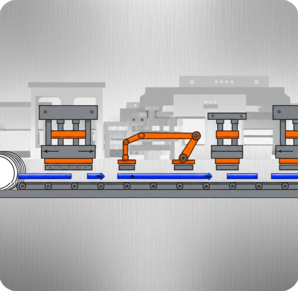
For high-volume runs of small, consistent parts, progressive die stamping is your go-to. The metal strip moves through a series of stations, with each stage performing a specific operation—think blank stamping, piercing, and bending—until the part is complete. The strip stays attached throughout, and precision piloting ensures accuracy.
If your part is larger or needs multiple complex forms (like deep shells or frames), transfer die stamping is often better. Here, each part is separated from the strip early and transferred between stations—either by hand or automation. This flexibility allows for more intricate drawing stamping operations, but the setup is more involved and may suit medium-volume production best.
Operation Sequencing and Die Addenda
So, how do you decide the order of stamping operations? Imagine assembling furniture—some steps must come before others, or nothing fits. The same applies to stamping: the sequence affects part quality, die life, and scrap rates. Group related features and operations to minimize tool changes and avoid collisions. For example, pilot holes are usually pierced first, followed by blanking, then any forming or bending.
- Pierce pilot holes for strip alignment
- Blank external contour
- Pierce functional holes and slots
- Form embosses, jogs, or flanges
- Bend features and create channels
- Deep draw or complex forming (if needed)
- Final cutoff and part separation
- Quality checkpoints after each critical stage
In progressive dies, features are grouped to maximize efficiency, but always check for potential tool collisions or geometric constraints. For deep draws, include addenda like draw beads and pressure pads to control material flow and reduce wrinkling or tearing. Transfer dies offer more flexibility for sequencing, especially when forming large or asymmetric parts (Springer).
Decision Matrix: Stamping vs. Alternative Manufacturing Processes
Not sure if stamping is the best approach? Let’s compare metal stamping dies with other fabrication methods. Sometimes, CNC machining or casting could be more economical or precise for low-volume or highly complex parts.
| Process | Cost Structure | Economic Order Quantity | Achievable Tolerances | Lead Time | Geometry Complexity |
|---|---|---|---|---|---|
| Stamping | High upfront die cost, low per-part cost | High (10,000+) | Moderate (±0.1–0.3 mm) | Medium (die build, then fast) | Moderate–High (with progressive/transfer dies) |
| CNC Machining | Low setup, high per-part cost | Low–Medium (<1,000) | High (±0.01–0.05 mm) | Short (no die), slower per part | Very High (complex 3D shapes) |
| Laser Cutting | Low setup, moderate per-part cost | Low–Medium | Moderate (±0.1 mm) | Short | High (2D, limited forming) |
| Casting | High mold cost, moderate per-part cost | Medium–High | Moderate (±0.2–0.5 mm) | Long (tooling, cooling) | Very High (complex, thick sections) |
| Injection Molding | High mold cost, low per-part cost | High (10,000+) | Moderate (±0.1–0.3 mm) | Medium–Long | Very High (plastics only) |
"Progressive die stamping is ideal for high-volume, small parts with consistent features. Transfer die stamping excels for larger, more complex forms or when multiple operations are required."
As you finalize your die strategy, remember: the right choice isn’t just about cost, but also about part quality, lead time, and your production goals. Once your operation sequence and die type are set, you’re ready to size the press and feed system—ensuring your stamping presses are matched perfectly to your chosen path.
Step 5: Size the Press and Feed System Correctly for Your Stamping Process
Press Tonnage and Energy Estimation Template
When it comes to stamping, choosing the right metal stamping press isn’t just about picking the biggest or most powerful machine in the shop. Imagine trying to use a sledgehammer for a finishing nail—it’s overkill and inefficient. The best stamping process starts with matching your press and feed system to your part geometry and die requirements. But how do you do that?
-
Estimate Required Tonnage: Calculate the tonnage needed for each operation:
- For blanking or piercing: Tonnage = Perimeter × Thickness × Shear Strength
- For forming or drawing: Tonnage estimation for forming or drawing processes is much more complex. It depends not only on the material's tensile strength but is also significantly influenced by part geometry, drawing depth, blank holder force, and friction. Simple formulas are not sufficient for accurate calculations. Industry best practice is to use professional CAE forming analysis software (such as AutoForm or Dynaform) for simulation to obtain precise tonnage curves and process parameters.
- Always add a safety margin (typically 15–20%) to cover material variability and unexpected loads (AHSS Insights).
- Check Press Bed Size and Shut Height: Confirm the die set fits within the bed, with enough daylight for maintenance and part removal. The slide capacity and shut height must match your die requirements.
- Assess Energy Needs: For deep draws or thick materials, ensure the press provides enough energy throughout the stroke—not just at bottom dead center. Mechanical presses deliver peak tonnage at the bottom, but may only offer 50% of that force a few inches above. This is especially critical for steel stamping press operations with advanced high-strength steels.
- Define Target Strokes Per Minute (SPM): Set your SPM based on part stability, lubrication, and heat management. High rates can cause overheating or instability if not properly managed.
- Specify Coil and Feed Line Specs: Align coil width, thickness, and straightness with your straightener and feeder capacity. Plan for rapid coil threading and easy cleaning to maximize uptime.
Press Sizing Table: From Inputs to Margin
| Tonnage Estimate Inputs | Calculated Tonnage | Press Rating | Safety Margin |
|---|---|---|---|
| Perimeter = 300mm Thickness = 2mm Shear Strength = 400MPa |
240 kN (example) | 250 kN | +4% |
| Area = 5000mm² Thickness = 2mm Tensile Strength = 500MPa |
500 kN (example) | 600 kN | +20% |
Note: Always confirm material properties with your supplier and validate calculations before purchasing metal stamping machines.
"Select a stamping press with enough energy at working stroke—not just at peak tonnage. Undersizing leads to fatigue, downtime, and higher costs."
Stroke Rate and Heat Management
Ever noticed how some jobs run perfectly at low speeds but struggle when you turn up the pace? As you increase SPM, friction and heat can build up, especially with thicker or high-strength materials. This is where proper lubrication and cooling strategies come into play. If your metal stamping press machine starts to overheat, you risk dimensional instability, tool wear, or even press damage.
- Set SPM based on part complexity, lubrication, and press type (mechanical, hydraulic, or servo).
- Monitor press temperature and plan maintenance intervals for high-volume runs.
- For critical jobs, consider presses with built-in cooling or advanced lubrication systems.
Feed Line, Straightener, and Coil Specs
Your stamping process is only as strong as its weakest link. If the feed line or straightener can’t keep up, even the best steel stamping press will sit idle. Modern metal stamping equipment often integrates coil feeding, leveling, and threading into a single system, reducing setup time and increasing reliability.
- Choose coil lines that match your material width and thickness needs.
- Look for quick-change features and hinged leveling units for easy cleaning and rapid coil threading.
- For heavy-gauge or high-speed applications, select feeder-levelers with robust rollers and ventilation for heat management.
By following this step-by-step approach, you’ll ensure your metal stamping machines and feed systems are precisely matched to your production goals. This not only maximizes efficiency and uptime, but also protects your investment—reducing the risk of downtime and scrap. Next, you’ll move on to building and validating your die setup, where robust construction and standardization make all the difference in long-term quality and cost control.
Step 6: Build the Die, Validate, and Standardize Setup in Metal Stamping
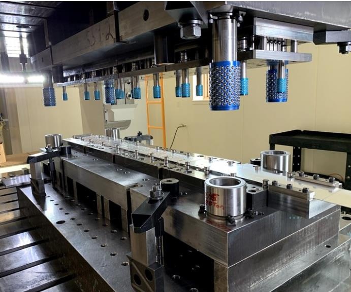
Die Construction and Material Choices: Why Getting it Right Matters
Ever wonder why some stamping dies last for hundreds of thousands of cycles while others need constant repair? The answer often starts with smart material choices and robust construction. When you build a custom metal stamping die, you’re not just shaping metal—you’re investing in the reliability and efficiency of your entire stamping process. The right die steels, coatings, and treatments are essential for handling abrasive materials and high production volumes without constant downtime.
- High-Speed Steel (HSS): Retains sharp cutting edges at high temperatures—great for high-speed operations and complex shapes.
- Carbide: Exceptional hardness and wear resistance, ideal for high-volume runs or abrasive materials, but more brittle and costly.
- Tool Steels (D2, M2): Offer a balance of toughness and hardness, resisting both wear and impact—common for punches and dies in demanding applications.
"Hardness and toughness are the foundation of a durable die—choose materials that match your production needs and the abrasiveness of your sheet."
Surface treatments and coatings (like nitriding or TiN) can further improve wear resistance and reduce galling. For sheet metal stamping dies facing high heat or friction, these choices prevent premature failure and help maintain dimensional accuracy over time.
Setup and First-Article Runbook: Standardizing for Consistency
Sounds complex? It doesn’t have to be. Imagine you’re assembling a complicated piece of furniture—without instructions, you’d waste hours on trial and error. The same goes for die setup. A standardized runbook ensures each installation is repeatable, safe, and optimized for quality output. Here’s a step-by-step outline you can adapt for your next custom metal stamping die:
- Clean the press bed and lower die seat—remove all debris for a level surface.
- Center the die on the press bed for uniform force distribution.
- Set the press stroke to inching mode and align the die halves (use shanks or alignment pins as needed).
- Clamp the upper die, insert a test strip or waste material, and adjust the slider to the correct height.
- Perform 2–3 empty strokes to check for smooth movement and proper clamping.
- Secure the lower die, check all sensors and safety interlocks, and confirm lube paths are clear.
- Run the first article, inspect for burrs, deformation, or alignment issues, and document all settings.
"A rigorous die setup isn’t just a checklist—it’s your insurance policy against crash risks, misalignment, and costly rework." (Henli Machine)
Maintenance Triggers and Regrind Criteria: Keeping Your Die in Top Shape
Even the best-built steel stamping dies need regular care. Think of it like maintaining a high-performance car—you wouldn’t skip oil changes or ignore warning lights. The same discipline applies here. Watch for telltale signs: burrs on parts, tolerances drifting, or unusual noises. These are your early warnings that maintenance or regrind is needed.
| Die Component | Material/Coating | Wear Indicator | Maintenance Action |
|---|---|---|---|
| Punch | D2 tool steel / TiN coating | Burr formation, edge rounding | Sharpen or replace |
| Die Plate | Carbide insert | Chipping, dimensional drift | Regrind or replace insert |
| Guide Pins/Bushings | Hardened steel | Excessive play, scoring | Replace or lubricate |
| Springs/Shims | Spring steel | Loss of force, breakage | Replace |
- Establish preventative maintenance intervals based on production volume and observed wear.
- Keep a log of sharpening, regrind, and component swaps—this helps predict future needs and reduces unexpected downtime.
- Use die electrical grease on electrical contacts or sensors to prevent corrosion and ensure reliable die protection systems.
"Preventative maintenance is the key to maximizing uptime and avoiding catastrophic failures in progressive metal stamping dies."
Pros and Cons of Common Die Steels and Coatings
High-Speed Steel (HSS)
- Pros: Excellent edge retention at high temperatures, good for high-speed stamping.
- Cons: Moderate toughness, higher cost than basic tool steels.
Carbide
- Pros: Extreme wear resistance, ideal for abrasive or high-volume jobs.
- Cons: Brittle, expensive, may require special handling.
Tool Steel (D2, M2)
- Pros: Good balance of hardness and toughness, widely available, cost-effective for most sheet metal stamping dies.
- Cons: May need surface treatment for maximum life in demanding applications.
In summary, building and validating your custom metal stamping die is a disciplined process that pays dividends in quality, uptime, and cost control. By standardizing setup and maintenance, you’ll minimize risk and ensure your stamping process runs smoothly—setting the stage for robust quality control and GD&T alignment in the next step.
Step 7: Run Production with Robust QC and GD&T Alignment for Quality Stamping
Run Parameters and the Control Plan: Keeping Production on Track
Ever had a batch of stamped parts drift out of spec halfway through a run? If so, you know the frustration of chasing problems that could have been prevented. In high-quality stamping and precision stamping operations, the key to consistent results is a well-structured control plan—one that locks in the critical process parameters and makes it easy to spot issues before they cause scrap or rework.
| Parameter | Target | Acceptable Range | Monitor Method | Reaction Plan |
|---|---|---|---|---|
| Lubrication Rate | 2 ml/min | 1.8 – 2.2 ml/min | Flowmeter, visual check | Adjust pump; inspect die for buildup |
| Strokes Per Minute (SPM) | 60 SPM | 55 – 65 SPM | Press controller | Reduce speed; check for overheating |
| Feeder Alignment | ±0.1 mm | ±0.2 mm | Optical sensor | Realign feeder; verify strip position |
| Die Protection Sensors | Active | All sensors functional | Sensor log | Stop press; investigate alarm |
By documenting these parameters and their acceptable ranges, you’ll make sure the production stamping process stays stable—reducing the need for constant adjustments and minimizing the risk of defects or downtime. This is the foundation of any robust quality stamping operation, as emphasized by industry leaders who rely on real-time monitoring and statistical process control (SPC) to maintain quality.
GD&T for Stamped Features: Aligning Inspection with Functional Needs
How do you ensure that your stamped parts will fit and function as intended? That’s where Geometric Dimensioning and Tolerancing (GD&T) comes in. GD&T is more than just a set of symbols—it’s a language for defining what matters most in your part’s geometry. By tying inspection directly to GD&T callouts, you enable precision stamping and reduce ambiguity for your quality team.
- Flatness on Pads: Ensures mounting or sealing surfaces are within specified tolerance—critical for assemblies.
- True Position on Pierced Holes: Controls the exact location of holes so mating parts align perfectly.
- Profile on Formed Contours: Verifies that complex bends or flanges meet their design shape.
In most cases, functional gauges are used for quick, in-process checks on high-volume production stamping lines. For more complex shapes or critical features, optical vision systems or coordinate measuring machines (CMM) offer higher accuracy. The choice depends on the criticality of the feature and the inspection resources available.
Use functional gauging for in-line checks of fit and assembly, but switch to metrology-grade CMMs when verifying complex profiles or when the highest accuracy is required.
Inspection Methods and Sampling: Ensuring Every Batch Meets the Mark
So, how often should you check your stamped parts? The answer depends on your CTQ (Critical-To-Quality) features and customer requirements. Leading manufacturers use a mix of real-time monitoring, in-line inspection, and scheduled audits to catch issues early. Here’s how a typical approach breaks down:
- In-line visual checks for surface finish and obvious defects every 10–20 parts
- Functional gauge checks for key dimensions at the start of each shift and after tool changes
- Statistical sampling (per your quality manual or customer contract) for dimensional and geometric tolerances
- Full CMM or optical scan inspections on first-article and periodic samples
For critical applications—think aerospace or medical—sampling rates may be higher, and traceability is essential. For automotive or general industrial production stamping, follow your documented control plan and adjust based on process capability studies or customer feedback.
Sampling plans should be tailored to your process capability and customer standards. When in doubt, start with your internal quality manual and refine as you collect process data.
By integrating robust QC, clear GD&T alignment, and disciplined sampling, you’ll catch problems early and deliver stamped parts that consistently meet or exceed expectations. This comprehensive approach not only reduces scrap and rework but also builds trust with your customers—setting the stage for fast, effective troubleshooting when issues arise. Ready to tackle defects head-on? The next step will show you how to map symptoms to root causes and rapid remedies.
Step 8: Troubleshoot Defects with a Defect-to-Remedy Matrix in the Stamping Process
Quickly Diagnosing Issues in the Sheet Metal Stamping Process
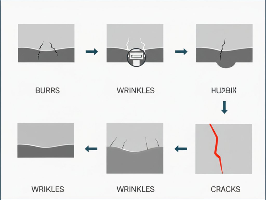
Ever run a stamping process and suddenly see burrs, wrinkles, or cracks? You’re not alone. Even with the best setup, defects can sneak in—costing time, scrap, and money. The key is a structured troubleshooting approach: map each symptom to its root cause, apply rapid tests, and lock in permanent fixes. Imagine having a playbook that lets your team spot and resolve issues before they snowball. That’s what this step is all about.
Defect Root Causes: What to Watch For
Let’s break down the most common defects in the stamping metal process and their likely origins. Standardizing terminology and defect photography helps teams diagnose consistently—no more guessing or vague descriptions. Here are some stamping examples you might encounter in production:
| Defect | Likely Root Causes | Quick Tests | Corrective Actions | Prevention |
|---|---|---|---|---|
| Burrs/Blanking Burrs | Worn or blunt cutting tools, excessive die clearance, improper material choice | Inspect tool edge, measure die clearance, check material spec | Sharpen/regrind punch & die, reset clearance, select proper grade | Schedule tool maintenance, verify material before run |
| Wrinkles | Uneven binder force, low material tension, poor die design | Check binder pressure, observe material flow during press | Adjust binder, add draw beads, redesign die addenda | Simulate forming, validate binder settings |
| Cracks/Splits | Excessive strain, small bend radius, brittle material, high press speed | Review bend radii, test with softer material, slow press speed | Increase radius, preheat or anneal, adjust speed | Check material ductility, optimize process parameters |
| Galling/Surface Strain | Insufficient lubrication, rough die surface, high friction alloys | Visual check for scoring, test alternate lubricant | Polish die, increase or change lubricant | Use compatible lubricants, maintain die surface |
| Indentations | Foreign particles in die, dirty metal surface, debris in press | Inspect die and blank for debris | Clean dies, improve cleaning before stamping | Implement pre-stamping cleaning, regular die inspection |
| Uneven Stretching | Improper die geometry, uneven force distribution | Measure thickness variation, observe strain pattern | Redesign die, adjust blankholder force | Simulate forming, validate die design |
| Bursting/Fracture | Stress concentration at holes/edges, material defects, excessive punch force | Check for sharp corners, inspect material, measure punch force | Add fillets, select better material, reduce punch force | Optimize die fillets, use quality-certified material |
First checks: Always verify die cleanliness and strip alignment before making deeper process changes. Many defects in the sheet metal stamping process can be traced to simple issues like debris or misalignment.
Corrective Actions by Operation: Rapid Tests and Permanent Fixes
Once you spot a defect, act fast. Here’s how to triage and resolve issues in the stamping process:
- Burrs: Try a quick tool inspection—if edges are dull, sharpen or replace. If burrs persist, check die clearance and material hardness.
- Wrinkles: Adjust binder force or add draw beads. Wrinkles often signal that the material isn’t held tightly enough during forming.
- Cracks/Splits: Slow the press speed, increase bend radii, or switch to a more ductile material. If splits occur near bypass notches in sheet metal stamping dies, review notch geometry and purpose to reduce stress concentration.
- Galling: Test alternate lubricants or polish the die. In high-speed runs, increase lubrication frequency.
- Indentations: Clean dies and blanks thoroughly. Even a small particle can leave a visible mark on finished parts.
- Uneven Stretching: Check for uneven die geometry or blankholder force. Use forming simulation to predict and correct issues.
- Bursting/Fracture: Reduce punch force, add fillets, or select a higher-quality material to prevent stress risers.
These corrective actions are based on proven stamping technology and industry best practices.
Prevention and Monitoring Signals: Staying Ahead of Defects
Want to catch problems before they ruin a batch? Use process monitoring and sensor alarms to spot early warning signs:
- SPC (Statistical Process Control) signals: sudden drift in part dimensions, Cpk drop, or out-of-control points
- Press alarms: unexpected tonnage spikes, feeder misalignment, or die protection sensor triggers
- Visual cues: change in part color, surface finish, or edge quality
- Operator feedback: unusual noises, vibration, or sticking during press cycles
“A disciplined inspection and monitoring plan is your best defense against costly defects in the stamping metal process. Early detection saves time, money, and reputation.”
By using this matrix approach, you empower your team to resolve issues quickly—minimizing downtime and scrap. When you standardize inspection terms and corrective actions, troubleshooting becomes routine, not a fire drill. Ready to take control of costs and quality? The next step will show you how to build a transparent cost model and select partners who can help you de-risk your stamping process from design to delivery.
Step 9: Estimate Cost and Select a CAE-Driven Partner for the Stamping Process
Tooling Amortization and Per-Part Cost Templates
Ever tried to budget a stamping project only to be surprised by hidden costs or shifting delivery dates? You’re not alone. In the automotive stamping process and other high-volume production environments, understanding the true cost structure is critical for avoiding overruns and delays. Let’s break down a transparent model that covers all the bases—so you can make confident decisions before committing to a stamping plant or supplier.
Start by mapping every major cost driver. Here’s a practical formula used in the industry:
Per-part cost = Material + Processing + Overhead + Scrap – Recovery + (Tooling Amortization ÷ Total Units)
- Material: Sheet metal, coil, or blank cost, plus waste from trim and scrap.
- Processing: Press time, operator labor, and secondary operations (deburring, cleaning, finishing).
- Overhead: Plant utilities, maintenance, quality checks, and management.
- Scrap – Recovery: Account for expected yield losses, but also any value from recycled scrap.
- Tooling Amortization: Spread the one-time die investment over your planned production volume. High-volume jobs benefit most from this approach.
Here’s how stamping compares to other processes for cost and value:
| Process | Tooling Cost | Per-Part Cost | Volume Suitability | Lead Time | Typical Tolerances | Complexity |
|---|---|---|---|---|---|---|
| Stamping | High (amortized) | Low (at scale) | 10,000+ | Medium (die build, then fast) | ±0.1–0.3 mm | Moderate–High |
| CNC Machining | Low | High | 1–1,000 | Short (setup only) | ±0.01–0.05 mm | Very High |
| Laser Cutting | Low | Moderate | 10–5,000 | Short | ±0.1 mm | High (2D only) |
| Casting | High | Moderate | 5,000+ | Long | ±0.2–0.5 mm | Very High |
Supplier Evaluation Criteria: Building a Robust Scorecard
Choosing the right metal stamping company or stamping plant isn’t just about price. Imagine you’re hiring a contractor for your home—you wouldn’t pick the lowest bid without checking their experience, tools, and track record. The same goes for stamping partners. Here’s a scorecard approach, drawing from proven industry evaluations (Wayne State University):
-
Shaoyi Metal Technology (Automotive Stamping Dies):
- Advanced CAE simulation for die geometry and material flow
- IATF 16949 certified for automotive quality
- In-depth structural and formability analysis from day one
- Proven track record with 30+ global automotive brands
- Early engineering collaboration to reduce tryout cycles and cut tooling costs
- Supplier B:
- Strong machining and tryout capacity, but limited CAE simulation
- Standard ISO certification
- Experienced with mid-volume metal pressing services
- Supplier C:
- Competitive pricing, but longer lead times and less experience with automotive stamping
- Limited on-site support for launch
- Basic die design and engineering simulation
Tip: Always tailor your scorecard to your specific part, volume, and quality needs. Look beyond initial price—consider technical capability, launch support, and real-world results.
When Advanced CAE Adds Value in the Automotive Stamping Process
Why prioritize suppliers who invest in computer-aided engineering (CAE)? Imagine catching a forming defect or springback issue before you’ve even cut steel—CAE makes that possible. In the automotive stamping process, CAE simulation helps optimize die design, predict material flow, and reduce the number of physical tryouts needed. This means:
- Shorter lead times from design to production
- Lower risk of late-stage changes or scrap
- More reliable first-pass yield, especially on complex or tight-tolerance parts
For example, a stamping plant using CAE can simulate draw beads, blankholder forces, and even spot potential wrinkles or splits—saving weeks of trial and error. This is especially valuable for automotive stamping, where launches are time-critical and dimensional accuracy is non-negotiable.
Lead Time Mapping: From PO to PPAP
To keep your project on schedule, map the journey from purchase order (PO) to production part approval process (PPAP):
- Design review and DfM (Design for Manufacturability) kick-off
- CAE simulation and die design freeze
- Die build and machining
- Tryout and first-article inspection
- Capability runs and PPAP submission
- Full production launch
Checkpoints at each stage help you catch bottlenecks early and adjust as needed—especially when working with metal stamping manufacturers on global programs.
“A transparent cost and lead-time model, paired with a CAE-driven partner, is your best defense against surprise overruns and launch delays in the stamping process.”
By following this structured approach—cost modeling, supplier scorecarding, and leveraging CAE—you’ll set your automotive stamping process up for success. The right partner will help you cut risk, control costs, and deliver quality parts on time, every time.
Frequently Asked Questions About the Stamping Process
1. What are the main steps in the stamping process?
The stamping process involves defining requirements, selecting materials, applying design for manufacturability (DfM) rules, choosing die strategies, sizing presses and feed systems, building and validating dies, running robust quality control, troubleshooting defects, and estimating costs while selecting the right supplier. Each step ensures better part quality, lower scrap, and cost efficiency.
2. How does the stamping process differ from punching?
Stamping is an umbrella term covering various metal forming techniques—such as blanking, bending, and drawing—while punching specifically refers to creating holes in metal. Stamping can include punching as one operation but also involves shaping, forming, and assembling metal parts through multiple stages.
3. What factors influence material selection in the stamping process?
Material choice depends on factors like formability, springback tendency, corrosion resistance, weldability, and surface finish. The intended function of the part, production volume, and compatibility with lubricants and finishing processes also play a role, especially when working with alloys like aluminum or stainless steel.
4. How do you prevent common defects in sheet metal stamping?
Preventing defects requires a structured troubleshooting approach: regular die maintenance, correct die clearance, proper lubrication, and monitoring process parameters. Early detection through in-line inspections and sensor alarms also helps catch issues like burrs, wrinkles, or cracks before they escalate.
5. Why is CAE simulation important when selecting a stamping supplier?
CAE (computer-aided engineering) simulation allows suppliers to optimize die geometry and predict material flow before production. This reduces tryout cycles, minimizes costly late-stage changes, and improves first-pass yield—especially vital in automotive stamping where accuracy and speed are crucial.