 Small batches, high standards. Our rapid prototyping service makes validation faster and easier —

Metal Stamping Die Mastery: Design, Types, And Cost Breakdowns
How Metal Stamping Dies Work
Ever wonder how a flat sheet of steel transforms into a precise bracket, intricate automotive part, or the frame of your favorite device? The answer lies in the engineering marvel known as the metal stamping die. Sounds complex? Let’s break down what a stamping die is, how it works, and why understanding its anatomy is key to mastering the tool and die craft.
What is a Metal Stamping Die?
A metal stamping die is a custom-engineered press tool that cuts, forms, or shapes sheet metal by applying force through a die press, using matched punch and die components to achieve consistent, high-precision parts.
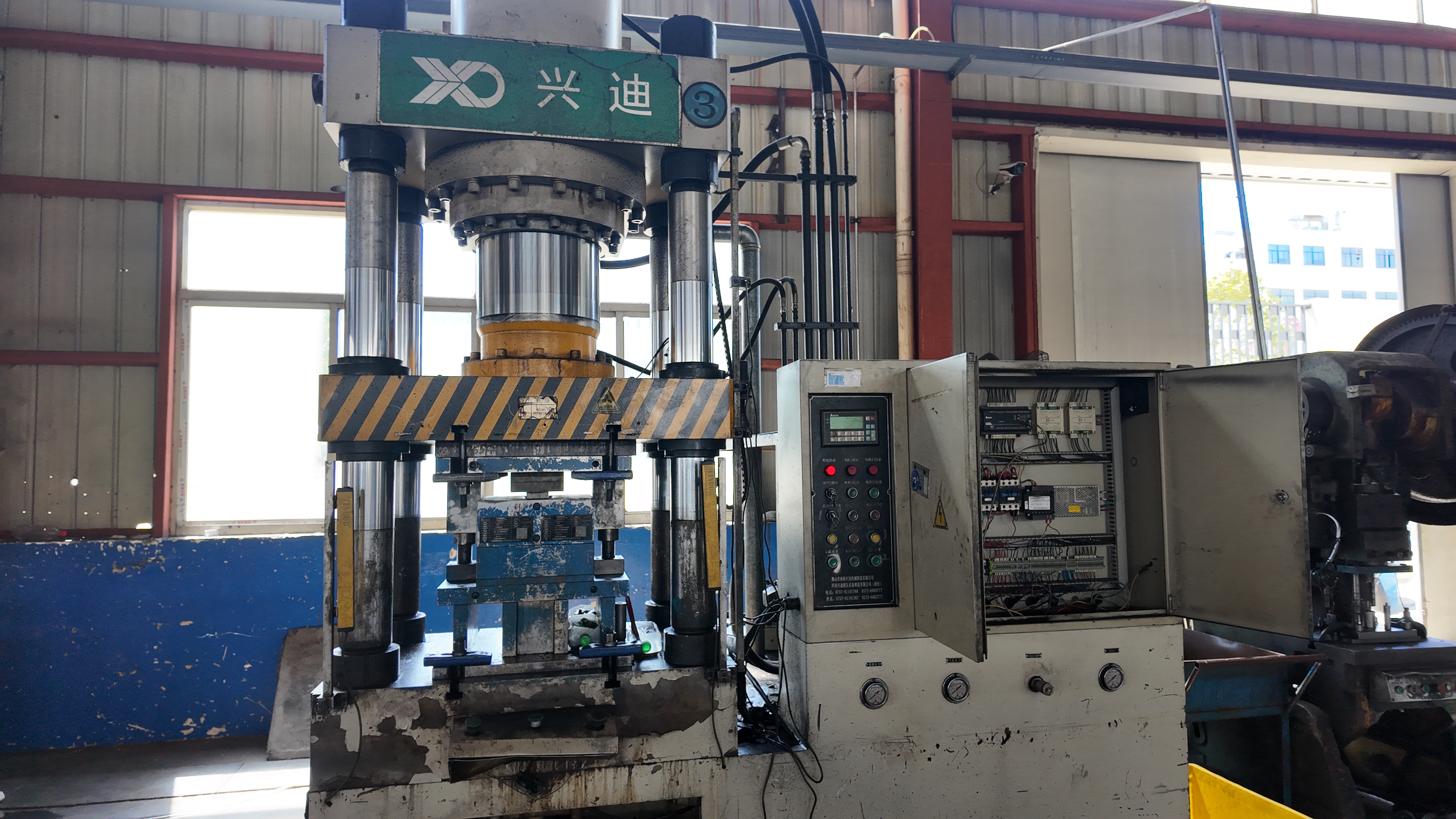
In tool and die practice, a metal stamping die is a robust, precision instrument—typically made from hardened tool steel or other wear-resistant materials—designed to repeatedly cut or form sheet metal into specific shapes. When placed inside a die press (sometimes called a press tool), the die set’s upper and lower halves come together, driven by the machine’s ram, to exert controlled force on the metal. This process is foundational in high-volume manufacturing across industries like automotive, electronics, and appliances.
Core Components of a Die Set
Imagine looking inside a die set. You’ll notice several key components, each serving a vital function:
- Die Plates / Shoes / Die Set: The structural base for mounting all other die components. Usually made from steel or aluminum, these plates are machined flat and parallel for accuracy and strength. The upper and lower die shoes, assembled with guide pins, form the complete die set.
- Punches: Hardened tools that move down to cut or form the sheet metal. Their nose shape (round, square, custom) determines the resulting hole or form. Punches are retained in the upper die shoe.
- Die Block / Die Button: The lower component with a matching opening for the punch. It provides the opposite cutting edge and absorbs the forming or cutting force.
- Strippers: Spring-loaded or fixed plates that hold the sheet metal flat and strip it off the punch after each press cycle, preventing jams and ensuring consistent part release.
- Guide Pins and Bushings: Precision-ground posts and sleeves that align the upper and lower die shoes during each stroke, ensuring repeatable accuracy.
- Heel Blocks and Heel Plates: Reinforce the die set, absorbing side thrust and preventing misalignment during off-center or high-force operations.
- Springs (Coil, Gas, or Urethane): Provide the force needed to hold, strip, or form the metal. Spring selection depends on required force, life expectancy, and cost.
- Retainers: Secure punches and die sections in their correct positions within the die set, allowing for quick maintenance and precise alignment.
- Pressure Pads and Draw Pads: Hold or control the metal during forming and drawing operations, ensuring proper metal flow and minimizing defects.
Each die set can be customized with additional features, such as sensors for process monitoring or special retainers for complex shapes.
How Dies Shape Sheet Metal: Blanking, Piercing, Forming, and More
So, how does a metal die actually transform sheet metal? The answer lies in the specific operations performed inside the die press:
- Blanking: The die cuts out a flat shape (the "blank") from the sheet. The blank becomes the finished part; the remaining material is scrap.
- Piercing: Punches create holes or slots in the metal. Here, the removed piece is scrap, and the sheet is the product.
- Forming: The die bends or shapes the metal without cutting it, producing flanges, ribs, or curves.
- Coining: The die compresses the metal between two surfaces, imprinting fine details or sharp features with high force.
Other related processes include notching, lancing, and drawing—each tailored to produce specific features or geometries in the sheet metal.
Die Set vs. Die Press: Clearing Up the Confusion
It’s easy to mix up the terms. The die set is the tool containing all the working components, while the die press (or press tool) is the machine that supplies the force. The two work together: the press drives the die set, and the die set shapes the metal.
Quick Reference: Key Die Components and Their Functions
- Die Plates/Shoes: Foundation for the die assembly
- Punch: Cuts or forms the metal
- Die Block/Button: Receives the punch and absorbs force
- Stripper: Removes metal from the punch
- Guide Pins/Bushings: Ensure precise alignment
- Heel Blocks/Plates: Prevent side movement
- Springs: Provide holding/stripping force
- Retainers: Hold punches and sections
- Pressure/Draw Pads: Control metal flow/forming
Understanding these components and operations gives you a solid mental model of how a metal stamping die works—and why mastering die sets is foundational to any tool and die or sheet metal stamping career.
Choosing Among Stamping Die Types
Faced with a new part design, you might wonder: Which types of stamping dies will deliver the best results for your project? Whether you’re planning a high-volume run or a custom prototype, understanding the strengths and trade-offs of each die type is essential to optimizing your sheet metal stamping process.
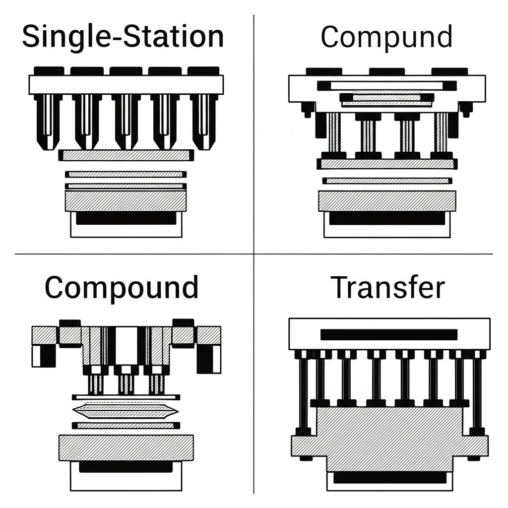
Progressive vs Transfer vs Compound Dies
Imagine you’re tasked with producing thousands of complex brackets, or maybe just a handful of custom-shaped connectors. The die you choose directly impacts efficiency, cost, and final part quality. Let’s break down the core types:
| Die Type | Working Principle | Best For | Production Scale | Material Utilization | Setup Complexity | Automation Level |
|---|---|---|---|---|---|---|
| Single-Station Die | Completes one punching or forming process per stroke | Simple parts, frequent design changes | Small batch | Lower | Simple | Low |
| Progressive Die | Performs several operations at different stations as the strip advances | Complex parts, high repeatability | Large batch | High | High | High |
| Compound Die | Simultaneously performs multiple operations (e.g., blanking + piercing) in one stroke | Flat, precise parts | Medium batch | High | Moderate | Some |
| Transfer Die | Mechanically or manually moves the part between stations for separate operations | Large, complex shapes; deep draws | Medium to large batch | High | High | High |
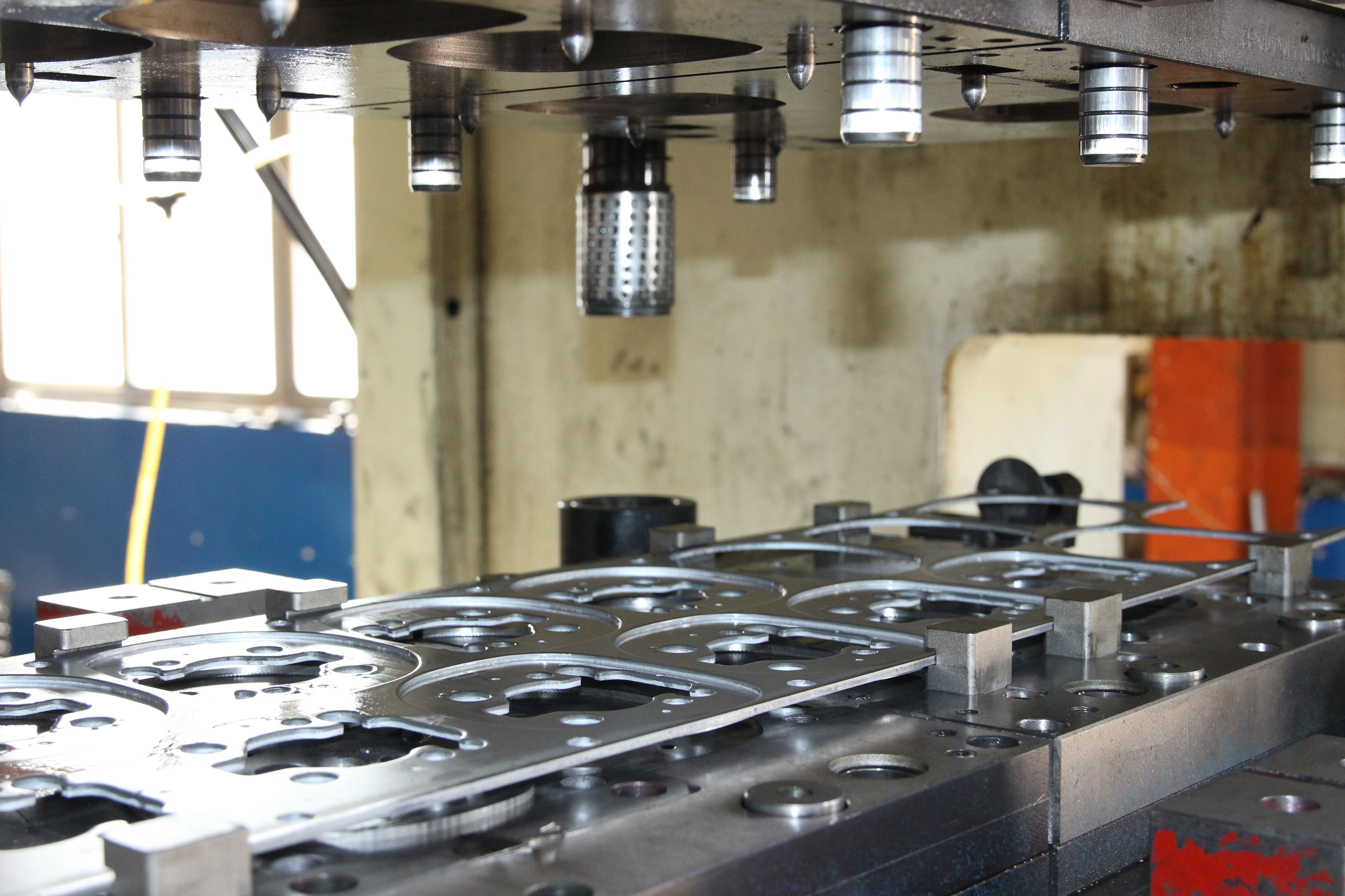
Each approach has its niche. For example, progressive dies excel at high-speed, high-volume runs where each strip of material undergoes a series of operations in one continuous pass. This is the go-to for automotive clips, electrical terminals, and other mass-produced items where the sheet metal stamping process must be both efficient and repeatable.
By contrast, transfer die stamping shines when you need to form large panels or deep-drawn parts that require the workpiece to be separated from the material strip and transferred through multiple stations—think appliance housings or automotive body panels.
Compound die stamping is the choice for high-precision, flat parts where blanking and piercing must occur in perfect alignment, all in one press stroke. It’s a favorite for washers, gaskets, and other components requiring tight tolerances but not complex forms.
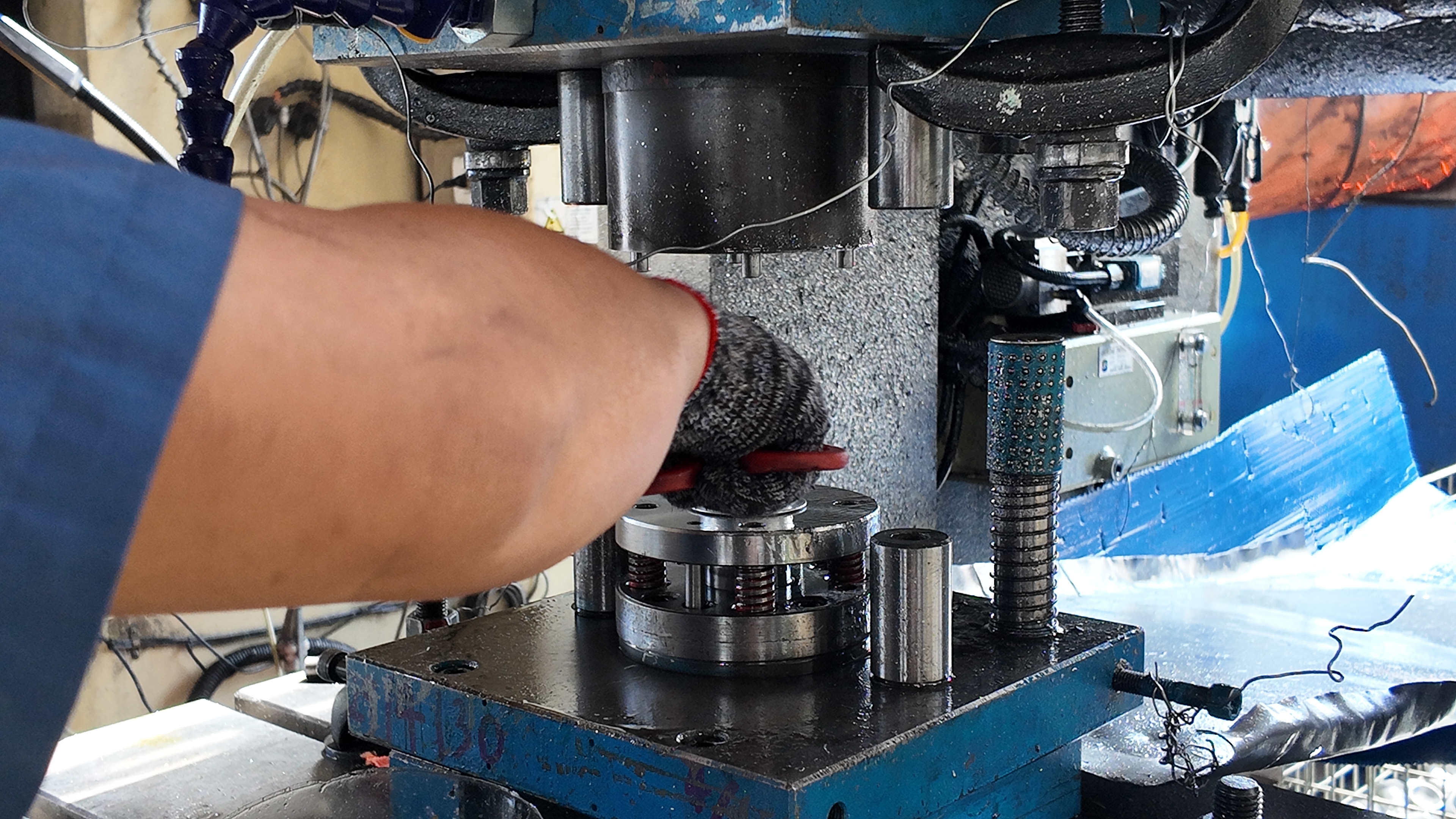
When Single-Station Tooling Makes Sense
Not every job calls for a sophisticated die set. If your production run is small or you anticipate frequent design changes, a single-station die (sometimes called a single punch die) may be the most economical. These dies are simple to design, quick to set up, and cost-effective for prototypes or low-volume parts. However, their lower efficiency and higher labor requirements make them less suitable for mass production.
Die Type Selection Factors: A Practical Decision Path
Choosing the right die for your sheet metal stamping process is about more than just part geometry. Here’s a step-by-step guide to help you decide:
- Assess Part Geometry: Is your part flat/simple, or does it require multiple forms and holes?
- Estimate Production Volume: Will you be making hundreds, thousands, or millions?
- Review Tolerance Requirements: Do you need ultra-high precision, or are standard tolerances acceptable?
- Consider Material Type and Thickness: Softer metals may work with standard dies; harder or thicker materials may require custom solutions.
- Plan for Feeding Method: Will you use coil feed (ideal for progressive dies) or blanks (often used with transfer dies)?
- Analyze Cost and Lead Time: Factor in tooling investment, setup time, and expected scrap rates.
By following this decision path, you can match your application to the optimal die type—balancing cost, efficiency, and part quality every step of the way.
Next, let’s walk through the workflow that takes you from part print to a buildable die, ensuring your stamping tooling delivers reliable results in production.
Die Design Workflow From Part to Production
When you hold a finished stamped part, it’s easy to forget the rigorous planning and engineering that brought it to life. But behind every reliable production run is a robust stamping die design process—one that balances manufacturability, cost, and quality from the very first sketch. Wondering how to turn a part print into a high-performing die assembly? Let’s walk through the workflow, phase by phase, using proven best practices from industry leaders.
From Part Print to Strip Layout
- Requirements Capture: Start by analyzing the part print. Ask: Is stamping the most effective way to make this part? Check for complex forms, tight radii, or features that might cause cracking or wrinkling. This is your first Design for Manufacturability (DFM) checkpoint.
- Material & Thickness Confirmation: Confirm the sheet material type, thickness, and grain direction. These details drive every downstream decision in metal stamping die design.
- Process Selection & Station Planning: Decide on the stamping process—progressive, transfer, or compound—based on part complexity and volume. Plan out the number and type of stations required for each operation.
- Strip Layout & Nesting Optimization: Develop a strip layout that details how the sheet will move through each station. Optimize for minimal scrap, robust carrier strength, and efficient material use.
- Checklist for this phase:
- Review grain direction for forming operations
- Ensure minimum webbing between features
- Validate carrier strength for progressive dies
- Plan for effective scrap management
- Account for burr direction and ejection
Sequencing Operations for Stability
- Pilot and Feed Progression: Design pilots and feed mechanisms to ensure the strip moves precisely from station to station. Consider idle stations if needed for stability or for placing larger tooling sections (The Fabricator).
- Die Block Sizing & Backing: Size die blocks and add backing plates to withstand forming forces and prevent deflection. Check that the entire die assembly fits within the target press bed and shut height.
- Clearances & Radii: Specify punch-to-die clearances and corner radii based on material and thickness. Proper clearances help reduce burrs and extend tool life.
- Form Stations & Draw Beads: Sequence forming operations to minimize springback and shock lines. Add draw beads or ribs to control material flow and strengthen carriers if needed.
- Checklist for this phase:
- Check for adequate lifter and return spring selection
- Confirm all features are supported during forming
- Review for potential weak points in carrier webs
- Plan for burr direction—downward for easier removal
Guiding, Stripping, and Sensor Strategy
- Cam/Side-Actions: Integrate cams or side actions if the part requires features that can’t be made from a straight press stroke. Ensure proper timing and clearance for all moving elements.
- Sensors & Mistake-Proofing: Incorporate sensors to detect misfeeds, part presence, and strip end. Add mistake-proofing features to prevent double hits or misaligned material. This is essential for modern stamping tooling and high-volume runs.
- Tryout Plan & Acceptance Criteria: Before releasing the die for production, develop a tryout plan. Define acceptance criteria for part dimensions, burr height, and surface finish. Use digital simulation tools (like FEA) to predict issues such as springback or tearing, and refine the die design before steel is cut.
- Checklist for this phase:
- Confirm all guide pins and bushings are specified for alignment
- Plan stripper plate design for consistent part release
- Specify sensor types and locations
- Document all critical-to-quality features for inspection
“A systematic, multi-stage approach to metal stamping design is the surest way to minimize costly errors and ensure reliable, high-quality production.”
Best Practices for Stamping Die Design and Tooling
- Always validate part design for manufacturability before die processing begins.
- Iterate strip layouts to maximize material use and minimize weak points.
- Leverage digital simulation for springback and force prediction.
- Document every phase—clear drawings, BOM, and inspection criteria are essential for seamless die assembly and troubleshooting.
By following this structured workflow, you’ll build robust, cost-effective stamping tooling that delivers consistent results on the shop floor. Next, we’ll dive into the essential calculations and sizing logic that underpin reliable die processing and press selection.
Essential Calculations for Reliable Tooling
When it’s time to turn your die design into reality, the right calculations make all the difference between a smooth production run and costly surprises on the shop floor. But where do you start? Let’s break down the key formulas and logic every engineer should know when planning a metal stamping process—from punch-to-die clearance to press tonnage and beyond. Imagine you’re speccing a new die for press: these calculations are your roadmap to a robust, efficient, and safe operation.
Clearance and Edge Conditions
Ever notice how a crisp cut or a ragged edge can make or break a stamped part? That’s where punch and die clearance comes in. Clearance is the gap between the punch and die edges—too tight, and you risk excessive wear and tool breakage; too loose, and you’ll see burrs and out-of-tolerance features. Here’s how to get it right:
- Material Matters: Harder, thicker materials require larger clearances; softer, thinner ones need less.
- Standard Rule of Thumb: A typical clearance is 10% of the material thickness per side, but can range up to 20% for harder metals or longer tool life.
- Fine Blanking Exception: For ultra-precise parts, clearances may drop below 5%—but this puts more strain on your die stamp and shortens tool life.
"Proper clearance ensures clean, precise cuts with minimal burrs and maximizes the lifespan of your stamp die tooling."
To calculate actual clearance: Clearance (per side) = Material thickness × Recommended % (e.g., 0.8 mm sheet × 10% = 0.08 mm per side).
Tonnage and Press Selection
Choosing the right press isn’t just about brute force—it’s about matching your stamping and pressing needs to the press’s capabilities. The two most common calculations are for blanking/piercing and for bending/forming:
| Operation | Inputs | Formula | Outcome |
|---|---|---|---|
| Blanking/Piercing | Perimeter (L), Thickness (t), Shear Resistance (s), Safety Factor (k) | P = L × t × s × k | Press force (tons) for blanking/piercing |
| Bending/Forming | Bend Length (L), Thickness (t), Tensile Strength (σb), V-width (V), Correction Factor (C) | P = C × L × t × σb / V | Press force (kgf) for bending |
- For blanking: P (tons) = Perimeter × Thickness × Shear Resistance × Safety Factor
- For bending: P (kgf) = Correction Coefficient × Bend Length × Thickness × Tensile Strength / V-width
Let’s see this in action. Suppose you’re blanking a 100 mm perimeter part from 3 mm thick stainless steel (shear resistance = 53 kgf/mm², safety factor = 1.1):
- P = 100 mm × 3 mm × 53 kgf/mm² = 15,900 kgf → 15.9 metric tons
When selecting a press, a safety factor needs to be considered (usually 1.1-1.3), so a press with a nominal force greater than 15.9 × 1.1 = 17.49 tons should be selected.
For a sheet metal die forming operation, always check that your chosen die for press fits within the press’s shut height, stroke, and bed size. Don’t forget to account for off-center loading and energy requirements, especially for progressive dies or large transfer dies.
Bend Allowance and Blankholder Force
Ever had a part crack or not fit after bending? Calculating bend allowance and blankholder force is your safeguard:
- Bend Allowance: The extra material needed to account for stretching during bending. While formulas vary, always reference your material’s properties and part geometry for accurate results.
- Blankholder Force: The downward force that keeps material from wrinkling or slipping during deep draws. Sizing this force requires knowledge of your material’s yield strength, thickness, and part shape.
For most sheet metal die operations, manufacturers use simulation tools or empirical data to fine-tune these settings. But as a rule, always err on the side of caution—undersized blankholder force can ruin a run, while excessive force can thin or tear the workpiece.
"A well-calculated stamp die reduces rework, extends tool life, and keeps your stamping process running smoothly."
Quick Reference Table: Key Inputs and Formulas for Stamping and Pressing
| Input | Formula | Outcome |
|---|---|---|
| Perimeter, Thickness, Shear Resistance, Safety Factor | P = L × t × s × k | Blanking/Piercing Tonnage (tons) |
| Bend Length, Thickness, Tensile Strength, V-width, Correction Coefficient | P = C × L × t × σb / V | Bending/Forming Tonnage (kgf) |
| Material Thickness, Clearance % | Clearance = t × % per side | Punch-to-Die Clearance |
- Always confirm material properties (shear resistance, tensile strength) from datasheets or supplier-provided specs.
- Apply a safety factor (typically 1.1–1.2) to account for variations in the stamping process.
- Check press shut height, bed size, and off-center load limits before finalizing your die selection.
By mastering these calculations, you’ll ensure your stamping and pressing operations are reliable, cost-effective, and ready for production. Next, we’ll explore how to inspect and control quality for every stamped part that comes off your line.
Quality Control and Tolerancing Essentials
When you’re aiming for flawless precision die and stamping results, how do you know if your stamped parts truly meet the mark? Imagine a scenario where every batch of stamped components performs perfectly on the assembly line—no unexpected burrs, no out-of-round holes, and no surprises at audit time. Achieving this level of quality isn’t luck; it’s the result of well-defined acceptance criteria, robust inspection methods, and industry-recognized documentation. Let’s break down what “good” looks like for stamped sheet metal and stamped steel parts, so you can set a clear standard and pass every audit with confidence.
Class A Acceptance Criteria: What Sets the Bar?
Not all defects are created equal. In the world of sheet metal stampings, quality is typically graded by severity—Class A, B, and C—so teams can prioritize which issues must be addressed immediately. Class A defects are the most critical: they are visible to untrained users, affect function or fit, or would be completely unacceptable to customers. For example, a crack in a structural bracket or a heavy burr that could injure an operator must be “frozen” (quarantined) as soon as it’s discovered.
- Class A defects: Obvious cracks, deep scratches, thick burrs, severe deformation, or missing features. These defects make stamped parts unfit for use and must be removed from the production stream immediately.
- Class B defects: Visible but less severe—such as minor surface marks or moderate burrs—may be repairable or acceptable in non-critical areas.
- Class C defects: Only detectable upon close inspection or after polishing; these may be tolerated in hidden or non-functional zones, provided they meet customer standards.
Always refer to customer drawings or specifications for the exact acceptance thresholds, and document any deviations for traceability.
Critical-to-Quality Dimensions: What Should You Measure?
Sounds complex? It doesn’t have to be. The key is to focus on features that truly affect the part’s function, assembly, or downstream processing. Here’s a quick checklist of control priorities for most stamped sheet metal and stamped steel parts:
- Burr height (especially at trimmed and punched edges)
- Edge quality (no sharp or ragged edges)
- Flatness and warpage
- Hole size and positional tolerance
- Springback on formed flanges
- Surface finish on cosmetic faces
- Carrier break-off quality (for parts on carrier strips)
For each feature, insert the measurement limits from your drawing or customer specification—don’t rely on memory. ISO 9001 and IATF 16949 frameworks both require that these critical-to-quality (CTQ) features be documented and traceable throughout production.
Inspection Methods and Reporting: Building an Audit-Ready Process
Inspection isn’t just about finding defects—it’s about using the right method for each feature and keeping reliable records. Here’s a practical table to help you match inspection methods to common features and potential issues:
| Feature | Potential Defect | Inspection Method | Instrument |
|---|---|---|---|
| Burr Height | Excess material, sharpness | Visual, tactile, micrometer | Micrometer, caliper |
| Hole Size/Position | Out-of-round, misalignment | Gauge, CMM, visual | Plug gauge, CMM |
| Flatness | Warp, bow | Surface plate, visual | Height gauge, dial indicator |
| Surface Finish | Scratches, pitting | Visual, touch, oiling | Gauze, oilstone, visual |
| Springback | Dimension out of spec after forming | Fixture, CMM | Inspection fixture, CMM |
| Edge Quality | Rough, cracked, or irregular edges | Visual, tactile | Visual, touch |
Inspection frequency and sample size should align with your quality management system—whether it’s ISO, Six Sigma, or an automotive-specific framework like NAAMS. For every batch of stamped components, keep clear records: first-article inspection reports, ongoing process checks, and certificates of conformance as required.
“Validate form and function before cosmetic perfection. A part that fits and performs reliably is the foundation of quality—cosmetic improvements come next.”
Industry Standards and Documentation: Your Roadmap to Audit Success
How do you ensure your precision die and stamping process stands up to customer and auditor scrutiny? Start by referencing established standards—ISO 9001 for general quality management, IATF 16949 for automotive, and NAAMS for die components. Use PPAP (Production Part Approval Process) elements to document CTQ features, inspection results, and corrective actions. This not only builds customer trust but also streamlines troubleshooting and continuous improvement efforts.
By focusing on robust acceptance criteria, critical-to-quality dimensions, and systematic inspection methods, you’ll reduce scrap, minimize rework, and deliver stamped parts that exceed expectations. Ready to keep your operation running smoothly? Next, we’ll explore how preventative maintenance and rapid troubleshooting can keep your dies and presses in top shape—ensuring every run meets your quality standards.
Maintenance and Troubleshooting That Prevents Downtime
Ever had a die machine grind to a halt in the middle of a crucial production run? When you’re relying on stamp die sets to keep orders moving, even a minor issue can quickly snowball into missed shipments and costly downtime. The solution? A proactive approach to maintenance, paired with a rapid, systematic troubleshooting workflow. Let’s walk through the essentials every shop needs to keep stamping die components in top shape and avoid those dreaded emergency repairs.
Preventative Maintenance Checklist for Die Sets
Imagine maintenance as your insurance policy for uptime. Regular, structured care extends the life of every standard die and keeps your die tool running smoothly. Here’s a practical checklist you can adapt to your operation:
- Clean all die surfaces and remove debris after every run
- Deburr punches, dies, and strippers to prevent material buildup
- Check and replenish lubrication at all sliding and wear points
- Inspect fasteners for correct torque and tightness
- Examine guide pins, bushings, and heel blocks for wear or scoring
- Test spring force and replace weak or broken springs
- Verify sensor function for misfeed, part presence, and strip end detection
- Review alignment between die sets and the die machine before each setup
- Keep spares of high-wear stamping die components on hand for quick swaps
Following a preventative maintenance schedule—customized to your usage intensity and tracked with a work order system—reduces the risk of unexpected breakdowns and supports a culture of planned care.
Always follow lockout/tagout procedures before servicing any die tool or die machine. Safety is non-negotiable—never work on energized equipment, and document every maintenance action for traceability.
Rapid Troubleshooting Guide: From Symptom to Solution
When problems do arise, quick diagnosis is key. Here’s a table to help you connect common symptoms with their likely causes and corrective actions:
| Symptom | Likely Cause | Corrective Action |
|---|---|---|
| Burrs on parts | Worn punch/die edge, excessive clearance | Sharpen or replace punch/die; adjust clearance |
| Slug pull | Worn stripper or insufficient stripping force | Replace stripper; check spring force and alignment |
| Galling or scoring | Insufficient lubrication, material transfer | Increase lubrication; polish die surfaces; use harder tool steel |
| Misfeeds | Feed misalignment, worn pilots, sensor failure | Realign feed; replace pilots; test and replace sensors |
| Punch chipping | Incorrect material hardness, excessive force, misalignment | Verify material specs; check press setup; replace punch |
| Shock lines or part deformation | Poor die alignment, worn guide pins/heel blocks | Realign die sets; replace worn components |
| Misalignment between press and die assembly | Improper setup, damaged guide pins/bushings | Check press-to-die alignment; replace or repair guides |
For persistent or complex issues, save the last part and strip from the run, review the die design, and consult inspection reports—these clues help pinpoint root causes quickly.
When to Rebuild vs Retire Die Components
Wondering if it’s time to rebuild or retire a component? Use these practical guidelines:
- Rebuild when: Wear is limited to replaceable parts (punches, strippers, springs) and the die body remains in tolerance
- Retire or fully refurbish when: The die set shows recurring alignment issues, excessive wear on guiding surfaces, or cracks in structural elements
- Always reference OEM manuals and historical maintenance data before making major decisions
Data from previous work orders and systematic feedback can help refine your preventative maintenance plan and improve future stamp die sets (The Phoenix Group).
Building a Culture of Proactive Maintenance
It’s tempting to focus only on fixing urgent problems, but the most successful teams shift from firefighting to prevention. By standardizing maintenance routines, documenting every repair, and empowering technicians to spot early warning signs, you’ll keep your stamping die components reliable and your production lines running at peak efficiency.
Ready to optimize costs and lead times? Next, we’ll break down the key factors that drive die manufacturing expenses and how to create a bulletproof RFQ checklist for your next project.
Cost Models Lead Time and RFQ Checklist
When you’re preparing to invest in custom metal stamping dies, the price tag and delivery timeline can feel like moving targets. Why do quotes from different stamping die manufacturers vary so widely? And how can you ensure your RFQ captures every detail, so there are no surprises down the line? Let’s break down the cost drivers, lead-time influencers, and a practical checklist to streamline your die manufacturing journey—so you can compare apples to apples and make the best decision for your next project.
Cost Drivers and Tooling Classes
Imagine two nearly identical stamped parts—yet their tooling costs differ dramatically. What’s going on? The answer lies in the details: complexity, expected volume, and required tolerances. Here’s a table outlining the major cost elements and how each is affected by your part’s requirements:
| Cost Element | Description | Complexity/Volume Impact | Notes |
|---|---|---|---|
| Design/CAE | Engineering, CAD, and simulation for die design | Higher for complex geometry, tight tolerances, or advanced simulation needs | DFM reviews can reduce rework |
| Die Machining | Material cutting, shaping, and finishing | Increases with harder tool steels, intricate features, or premium materials | Longer for carbide or hardened steel |
| Standard Components | Guide pins, bushings, springs, fasteners | Minimal for simple dies; higher for large or automated sets | Standardization helps control cost |
| Heat Treat/Coatings | Processes to harden or protect tooling dies | Required for high-volume or abrasive materials | Adds both cost and lead time |
| Tryout/Debug | Initial testing, tuning, and process validation | Longer for tight tolerances or new part designs | May require multiple cycles |
| Spares/Consumables | Extra punches, strippers, springs | Higher for high-volume or critical uptime applications | Include in upfront quote |
Tooling classes also play a role. Class A dies are built for extreme volumes and longevity, with premium materials and robust construction—expect higher upfront costs, but lower per-part amortization. Class B and C dies suit lower volumes or prototypes, often with less expensive materials and shorter lifespans (The Fabricator).
Lead-Time Influencers in Die for Manufacturing
Ever wonder why one stamping die factory quotes 8 weeks and another 14? Lead times depend on more than just the complexity of your part. Here are the main factors:
- Material Availability: Specialty tool steels or imported alloys can add weeks—plan ahead for unique specs.
- Part Complexity: More features or tighter tolerances mean longer programming, machining, and inspection cycles.
- Shop Capacity: If your supplier is running at full tilt, expect longer scheduling windows for die machining and assembly.
- Secondary Processes: Heat treating, coatings, and outside services (like EDM or wire burning) can introduce extra wait time.
- Quality Control: Rigorous inspection and documentation, especially for automotive or aerospace, add steps but are essential for reliable tooling dies.
Pro tip: Communicate your critical deadlines and be transparent about annual volumes—this helps the supplier prioritize and allocate resources effectively.
RFQ and Acceptance Checklist: What to Include
Ready to request a quote? Don’t leave out the details that can make or break your project. Here’s an ordered checklist to ensure your RFQ covers all the bases and lets you fairly compare offers from multiple tool and die manufacturing partners:
- Part prints with GD&T (Geometric Dimensioning & Tolerancing)
- Expected annual and lifetime volumes
- Material specification and thickness
- Required cosmetic class (A/B/C)
- Die life expectations (cycles or years)
- List of spare punches, strippers, and springs needed
- Sensor and mistake-proofing requirements
- Tryout parts quantity and acceptance criteria
- PPAP (Production Part Approval Process) or other quality documentation levels
- Shipping, installation, and training scope
- Payment terms and milestone schedule
By providing this information upfront, you’ll get more accurate, comparable quotes and avoid costly change orders or delays once the project is underway.
Early DFM (Design for Manufacturability) reviews are the single best way to reduce change orders and keep your project on schedule. Engaging your supplier in DFM discussions up front can save time, money, and rework down the road.
Understanding Cost Amortization and Break-Even
Still wondering how to judge if a die quote is reasonable? Think in terms of amortization: spread the total tooling cost over the expected number of parts you’ll produce. For high-volume projects, a higher initial investment in premium tooling dies often results in a lower cost per part. For prototypes or low-volume runs, prioritize flexibility and lower upfront cost—even if the per-part price is higher.
Break-even analysis is another helpful tool. Compare the total cost of ownership (including die machining, maintenance, and spares) for different die classes against your projected order volumes. This helps you choose the most cost-effective solution for your unique needs.
By understanding the drivers behind die for manufacturing costs and lead times, and by using a structured RFQ checklist, you’ll set your project up for success—aligning procurement and engineering, and ensuring your next custom metal stamping dies deliver value from day one. Next, we’ll see how these principles apply in the high-stakes world of automotive stamping, where collaboration and CAE-driven design are the keys to launch success.
Automotive Die Excellence With CAE and Collaboration
Imagine launching a new vehicle platform—every sheet metal panel must meet strict tolerances, survive years of road stress, and be ready for mass production on a tight schedule. In the automotive world, the stakes for metal stamping die performance are incredibly high. So, what sets leading automotive stamping dies apart? The answer is a blend of advanced simulation, collaborative engineering, and a relentless focus on quality from RFQ to PPAP.
Why CAE Matters for Automotive Dies
Ever wondered how carmakers manage to deliver flawless body panels and intricate steel stamping parts at scale? The secret is Computer Aided Engineering (CAE). Modern CAE systems let engineers digitally simulate every step of the automotive stamping process—from material flow and thinning to predicting wrinkles, springback, or even surface defects. This upfront simulation helps avoid costly trial-and-error on the shop floor and shortens the tryout phase dramatically (ScienceDirect).
- Optimize die geometry for complex shapes and deep draws
- Predict and resolve forming issues before steel is cut
- Reduce the number of physical tryouts required
- Enhance material utilization and minimize scrap in production metal stamping
For example, Shaoyi Metal Technology leverages advanced CAE simulation to optimize their steel stamping dies, ensuring accurate material flow and robust part formation. This digital-first approach is now an industry best practice, especially for outer-body panels and structural components where dimensional accuracy is non-negotiable. Learn more about CAE-driven automotive dies.
Collaboration from RFQ to PPAP
Sounds complex? It’s actually all about teamwork. Successful automotive die projects rely on early and ongoing collaboration between OEMs, Tier 1 suppliers, and toolmakers. From the moment an RFQ is issued, engineering teams review designs together, conduct DFM (Design for Manufacturability) workshops, and use simulation data to align on the best die concepts. This cross-functional process ensures:
- Critical tolerances and cosmetic requirements are understood up front
- Potential issues—like splits or wrinkles—are addressed before tooling begins
- Die designs are validated for manufacturability and launch readiness
- Quality documentation and PPAP deliverables are built into the workflow
Shaoyi’s approach, for instance, involves in-depth structural reviews and formability analysis at every stage, helping customers avoid late tryout churn and costly rework. Their IATF 16949 certification is a mark of quality that assures automotive clients of robust process control and documentation.
Front-load engineering to avoid late tryout churn. Early simulation and structured design reviews compress timelines and deliver more robust steel stamping parts.
From Prototype to Mass Production: A Table of Automotive Die Solutions
| Provider | CAE Simulation Depth | Certifications | Tryout & Launch Approach | Production Scope |
|---|---|---|---|---|
| Shaoyi Metal Technology | Advanced material flow, springback, and formability simulation | IATF 16949 | Collaborative reviews, rapid prototyping, minimized tryout cycles | Prototype to high-volume sheet metal stamping press runs |
| Wiegel | High-speed stamping, in-die sensors, camera vision QC | IATF 16949:2016, ISO 9001 | Co-engineered solutions, real-time press monitoring | Precision electrical and non-electrical automotive parts |
| Carby Corporation | DFM collaboration, 3D modeling, deep drawn expertise | ISO 9001 | Early-stage engineering, custom solutions | Small, intricate deep drawn automotive components |
Key Takeaways for Automotive Die Cutting Success
- Invest in CAE simulation to optimize every automotive die cutting project
- Engage all stakeholders early—RFQ to PPAP—for seamless design handoff
- Choose partners with proven certifications and a track record in steel stamping
- Prioritize digital validation and structured reviews to reduce launch risk
By combining simulation-driven design with collaborative workflows, you can accelerate launches and achieve world-class quality in every production metal stamping run. As you move forward, consider how these best practices can be adapted to your next automotive project—ensuring your metal stamping die investment delivers both performance and peace of mind.
Frequently Asked Questions
1. What is a metal stamping die and how does it work?
A metal stamping die is a precision tool used with a press to cut, shape, or form sheet metal into specific parts. It works by using matched punch and die components that apply force to the metal, enabling high-volume production of accurate, repeatable parts in industries like automotive and electronics.
2. What are the main types of stamping dies?
The main types include single-station dies (for simple or low-volume parts), progressive dies (for complex, high-volume production), compound dies (for flat parts needing simultaneous operations), and transfer dies (for large or deep-drawn parts). Each type is chosen based on part complexity, volume, and production needs.
3. How do you select the right die type for a sheet metal stamping process?
Selecting the right die type involves evaluating part geometry, required tolerances, production volume, material type, and feeding method. Progressive dies suit high-volume, complex parts, while transfer and compound dies are ideal for large or precise parts. Cost, setup time, and automation needs also influence the decision.
4. How does maintenance affect the performance of stamping die components?
Regular preventative maintenance, such as cleaning, lubrication, and inspection of die components, is crucial for minimizing downtime, extending tool life, and ensuring consistent part quality. A proactive approach also reduces emergency repairs and supports efficient production.
5. What role does CAE simulation play in automotive stamping die projects?
CAE simulation enables engineers to digitally model material flow, predict forming issues, and optimize die geometry before production begins. This reduces trial-and-error, shortens launch timelines, and ensures that automotive stamping dies meet strict quality and durability requirements.