 Small batches, high standards. Our rapid prototyping service makes validation faster and easier —

Progressive Metal Stamping Costs: Tooling And Part Math
Progressive Metal Stamping Fundamentals
What Is Progressive Metal Stamping?
Ever wondered how millions of identical, high-precision metal parts are made so efficiently? Progressive metal stamping is the answer—a core process in modern manufacturing. But what is a stamping process like this, and how does it stand apart from other methods?
Progressive metal stamping is a highly automated process where a coil-fed strip of metal advances through a series of dies, each station performing a specific operation, to efficiently produce finished parts in sequence.
In essence, a long strip of sheet metal (the coil) is fed into a stamping press. This strip moves step-by-step through a progressive die, where each station pierces, bends, forms, or trims the metal. By the time the strip reaches the end of the tool, the finished part is cut off and separated—ready for use. This method is widely used for making complex, high-volume parts in industries like automotive, electronics, and aerospace.
Why Manufacturers Choose Progressive Tooling
Sounds complex? Actually, progressive stamping simplifies production for both simple and intricate parts. Compared to single-hit or stage tooling, where each operation is performed separately, progressive stamping combines all steps into a single, streamlined process. This not only boosts efficiency but also enhances consistency and safety.
- High throughput—thousands of parts per hour are possible, depending on part complexity and material
- Lower per-part cost at volume, thanks to automation and minimal manual handling
- Consistent positional accuracy, as each station is precisely aligned within the same die set
- Ability to handle complex features and tight tolerances in a single run
- Material versatility—works with steel, aluminum, copper, and more
How Progressive Stamping Differs From Transfer and Compound Dies
If you’re new to metal forming, you might be asking, “What is dies in manufacturing?” In metal stamping, a die is a specialized tool that shapes or cuts metal. Progressive die stamping uses a single die set with multiple stations, while transfer press stamping and compound dies handle parts differently.
- Progressive stamping: The strip remains attached throughout the process, advancing through each station before the finished part is cut off.
- Transfer press stamping: Parts are separated from the strip early and transferred individually between stations—ideal for larger or more three-dimensional shapes.
- Compound dies: Multiple operations occur at a single station, usually for simpler parts or when only a few features are needed.
Progressive stamping stands out for its repeatability and cost efficiency in high-volume runs, while transfer and compound dies may suit other part types or lower volumes.
Core Benefits and Typical Use Cases
Why should engineers and buyers consider progressive die stamping? The process is designed for reliability, cost control, and safety. Automated feeding and built-in safeguards minimize manual intervention, reducing the risk of injury and ensuring each part meets strict quality standards. You’ll notice progressive stamping in everything from automotive brackets to electronic connectors—anywhere high volume and consistency are critical.
- Coil is loaded onto the feeder
- Strip advances into the progressive die
- Each station performs a unique operation (piercing, bending, forming, etc.)
- Finished part is cut off and ejected
- Quality inspection ensures standards are met
Looking for stamping examples? Think of automotive seatbelt components, electrical terminals, or appliance brackets—these are all products where progressive metal stamping shines.
By understanding what is a stamping process and how progressive dies work, you’re set to explore the rest of this guide with confidence. Next, we’ll dive deeper into the anatomy of a progressive die and what makes these tools so effective for high-volume manufacturing.
Progressive Die Components and Strip Layout
Inside a Progressive Die Assembly
Ever wondered what’s inside a progressive stamping die and how all those intricate features come together to create parts at lightning speed? Let’s break down the anatomy of a progressive die and how its components work in harmony to deliver high-volume, precision results.
- Strip layout: The roadmap that defines how the metal strip moves and where each feature is formed or cut.
- Pilots: Pins that register the strip’s position, ensuring each station aligns perfectly for every press stroke.
- Carriers: The connecting web that keeps parts attached to the strip as they travel through the die.
- Lifters: Devices that raise or support the strip or part during certain operations, preventing distortion or jamming.
- Strippers: Plates or mechanisms that hold the strip down and help release it from punches after each operation.
- Punches and dies: The heart of each station—punches cut or form the metal, while dies provide the matching cavity.
- Cut-off: The final station that separates the finished part from the carrier strip.
Key Progressive Die Components Explained
Imagine the progressive stamping die as a well-orchestrated assembly line, where each component plays a specific role. Here’s a quick overview of the essential stamping die components you’ll encounter:
| Component | Purpose | Setup Notes |
|---|---|---|
| Pilots | Precisely locate and register the strip at each station | Critical for maintaining part-to-part accuracy |
| Carriers | Connect parts and transfer them through the die | Must be strong enough to prevent buckling; design with material thickness in mind |
| Lifters | Support or lift the strip/part during forming | Help prevent distortion, especially for complex geometries |
| Strippers | Hold strip in place and remove it from punches | Stripper force must balance holding and release; too much can deform parts |
| Punches | Cut or form features into the strip | Must align precisely with die cavities to avoid wear and maintain edge quality |
| Dies | Provide cavities for forming or cutting operations | Regular inspection and maintenance extend tool life |
| Guides/Bushings | Maintain alignment of moving die components | Essential for high repeatability and tool longevity |
| Sensors | Detect misfeeds, part ejection, or tool wear | Integrate for real-time feedback and die protection |
Strip Layout, Piloting, and Pitch Control
The strip layout is the foundation of every progressive die. It defines the sequence of operations and the spacing—known as pitch—between each part as it moves through the die. Getting this right is crucial for both part quality and material efficiency.
- Piercing: The first stations typically punch holes or slots in the strip.
- Forming: Subsequent stations bend, emboss, or coin the metal to create the desired shape.
- Trimming: Edges are cleaned up or refined for final geometry.
- Cut-off: The finished part is separated from the carrier strip.
Pilots are introduced early in the process to “lock in” the strip’s position, ensuring all downstream stations are perfectly aligned. This is why pilots are considered one of the most vital progressive die components for maintaining tight tolerances and consistent results.
Die Protection and Sensor Basics
With so many moving parts, how does a metal stamping die avoid costly crashes or misfeeds? Modern progressive dies often incorporate a range of sensors and protection systems:
- Limit switches to check strip advancement (ideal for slower speeds)
- Touch probes or light beams to verify part presence and ejection
- Microdetection systems for ultra-precise monitoring of die movement and position
- Tonnage wave analysis to detect abnormal force or tool wear
Integrating these systems not only protects the stamping dies but also enables higher production rates with fewer interruptions. Regular alignment checks, die set rigidity, and accessible maintenance points are best practices to keep your metal stamping die running reliably.[The Fabricator]
By understanding the function and interplay of progressive die components, you’re better equipped to design, specify, or troubleshoot high-volume stamping operations. Next, we’ll look at how press selection and process capabilities tie directly into die design, ensuring every part meets its intended quality and cost targets.
Process Capabilities and Press Selection Guide
Selecting the Right Stamping Press
When it comes to progressive metal stamping, choosing the right stamping press is just as critical as designing the die itself. Imagine you’re tasked with producing high-volume, tight-tolerance parts—do you opt for a mechanical, hydraulic, or servo-driven press? The answer depends on your part geometry, material, and production goals.
| Press Attribute | Impact on Part Quality | What to Verify at RFQ |
|---|---|---|
| Press Type (Mechanical, Hydraulic, Servo) | Determines speed, flexibility, and suitability for part complexity | Match press type to part shape and production volume |
| Tonnage Capacity | Ensures the press can handle total force required for all die stations | Calculate total tonnage needed, including all operations and die features |
| Shut Height | Must accommodate die set and part height; affects tool life and safety | Verify shut height range matches die requirements |
| Stroke Rate (Speed) | Influences throughput and heat generation; higher speeds may affect accuracy | Check if press can maintain required speed without sacrificing part quality |
| Bed Size & Rigidity | Impacts die alignment, deflection, and long-term accuracy | Ensure bed size supports die footprint and minimizes deflection |
| Feed System Integration | Affects strip control, feed accuracy, and misfeed risk | Confirm compatibility with die stamping machine and automation |
Speed, Tonnage, and Shut Height Considerations
How do you know if a press is up to the task? Start by calculating the total tonnage required, which depends on the sum of all operations—piercing, forming, coining, and more—across each station in the progressive stamping press. Material thickness, tensile strength, and part perimeter all play a role. For example, higher-strength steels or thicker materials will demand more tonnage. If your design has many stations, the cumulative load can be significant, so always add up each station’s requirements.
Shut height—the distance between the press bed and slide when fully closed—must be compatible with your die set. If the shut height is too short or too tall, you risk tool damage or poor part quality. Always verify these specs during the RFQ process for your sheet metal die press.
Feed System Accuracy and Strip Control
Ever struggled with misfeeds or inconsistent part quality? The feed system is often the culprit. Whether you’re running a small stamping press or a high speed stamping line, your feed must deliver the strip precisely—every time. Factors like feed length, material width, pilot release timing, and feed window must be tightly controlled. For high speed metal stamping, servo-driven feeds offer the best combination of accuracy and programmability, but mechanical feeds may be suitable for simpler jobs.
- Flatness and camber of incoming coil
- Proper lubrication to reduce friction and tool wear
- Burr direction and edge quality
- Feed alignment and pilot pin engagement
Consistent feed accuracy is essential for progressive stamping press operations, especially as speeds increase. Misfeeds can lead to die crashes, scrap, and costly downtime.
Press stability and feed repeatability often matter as much as peak tonnage—don’t overlook them when selecting your die stamping machine.
When to Consider High Speed Stamping
Thinking about ramping up production? High speed metal stamping is ideal for small, flat parts where volume and efficiency are top priorities. But as stroke rates rise, trade-offs emerge: higher speeds can increase tool wear, make burr control more challenging, and demand tighter process control. Not every part or die design is suited for ultra-fast runs, so weigh the benefits against potential quality risks. Servo-driven presses and advanced feed systems are often the best fit for high speed stamping, balancing speed with accuracy and flexibility.
As you evaluate your process, remember that the right stamping press is the foundation of reliable, efficient progressive metal stamping. In the next section, we’ll explore how material choices and surface results further influence your stamping outcomes and quality targets.
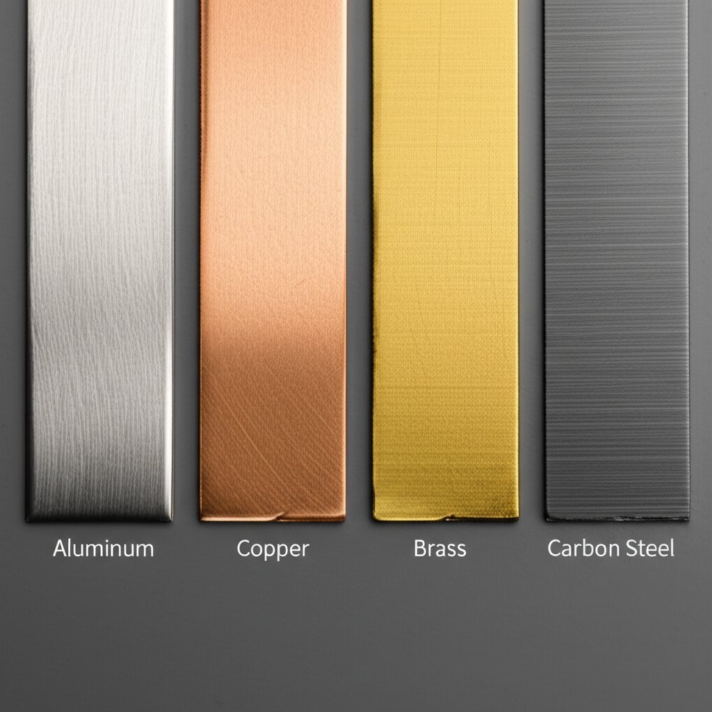
Material Choices and Surface Results in Progressive Stamping
Stamping Aluminum Alloys Without Compromising Edges
When you’re faced with selecting materials for progressive metal stamping, the choice goes far beyond cost. Have you ever noticed how some aluminum stamping parts come out flawless, while others show edge cracks or excessive burrs? The secret lies in understanding how each alloy behaves under the stresses of the aluminum stamping process—and how to design your die and process accordingly.
| Material | Typical Stamping Behavior | Design Notes | Post-Process Considerations |
|---|---|---|---|
| Aluminum & Alloys | Excellent formability, high strength-to-weight ratio, prone to springback, notch sensitive | Use larger bend radii (3x steel), sharp tools to minimize burrs, increase punch/die clearance, optimize carrier design for support | May require deburring; surface is highly corrosion resistant; consider pre- or post-plating for conductivity or appearance |
| Copper | Very ductile, excellent for piercing and forming, minimal springback | Keep tight tolerances, avoid excessive work hardening; design for electrical contact cleanliness | Often post-plated for conductivity; soft surface may need protective packaging |
| Brass | Good malleability, moderate hardness, attractive finish | Watch for galling; maintain smooth die surfaces; design for decorative and functional needs | Can be polished or plated; suitable for decorative and electrical applications |
| Carbon Steel | High strength, robust in forming, moderate springback | Requires higher tonnage; corrosion protection often needed; tighter radii possible than aluminum | Commonly zinc or nickel plated; monitor for burrs and heat-affected zones |
| Stainless Steel | Excellent corrosion resistance, higher forming force needed | Use robust carriers; plan for increased tool wear; may require specialized lubricants | Surface finish is critical for medical/food applications; often electropolished or passivated |
Copper and Brass in Progressive Dies
Copper progressive stamping and brass progressive stamping are popular for electrical and decorative components. You’ll notice copper’s softness allows for intricate forms and tight bends, but it can work-harden quickly if over-formed. Brass, on the other hand, balances malleability with enough hardness for mechanical features. Both require careful tool maintenance to avoid surface scratches or galling, and their conductivity often means post-stamping plating or cleaning is essential for reliable function.
Surface Finish and Burr Direction Management
Ever run your finger along stamped aluminum parts and found a sharp edge? Burrs are a natural byproduct of piercing and forming, but their size and direction can be managed. Here’s how:
- Orient critical edges away from functional or cosmetic surfaces in your strip layout
- Specify die clearances and sharpness based on material (aluminum needs sharper, smoother punches than carbon steel progressive stamping)
- Plan for secondary deburring if edge quality is a top priority
- Choose appropriate lubricants to reduce galling, especially for aluminum and brass
Finishing steps such as electropolishing, plating, or coating can further enhance appearance, smoothness, and corrosion resistance. For stamped aluminum parts, surface treatments may be required for electrical conductivity or visual appeal.
Material Temper, Springback, and Formability Tips
Material temper—the hardness or softness of your metal—directly impacts formability and springback. Softer tempers (annealed or O condition) are easier to form but may not hold shape as well. Harder tempers resist deformation but can crack if bends are too tight. For aluminum stamping dies, expect greater springback than with carbon steel progressive stamping; compensate by overbending or adjusting die geometry.
- Do use larger radii for aluminum and high-strength alloys to avoid cracking
- Do apply stable, high-quality lubricants to prevent galling, especially in aluminum stamping process
- Do select the right temper for your forming and end-use requirements
- Don’t overlook the need for secondary finishing if edge quality or surface appearance is critical
- Don’t ignore material grain direction—especially for deep draws or complex forms
- Don’t assume all plating is best done post-stamping; sometimes pre-plated strip improves efficiency and reduces secondary ops
By understanding how each material responds to progressive stamping, you can design better carrier systems, sequence stations more effectively, and deliver parts that meet both functional and cosmetic requirements. Next, let’s see how these material realities translate into actionable DFM rules and die design methods for your next progressive tooling project.
DFM Rules and Die Design Methods for Progressive Parts
Design For Manufacturability Essentials
Ever tried to take a great part design straight to production, only to hit a wall with manufacturability? With progressive stamping die design, a few early decisions can make or break your project’s efficiency, cost, and quality. Let’s walk through the must-follow rules that bridge the gap between concept and a robust, high-volume stamping tool and die.
- Define functional requirements early: What does the part need to do, and what are its critical-to-quality features?
- Select your material: Confirm thickness, temper, and surface finish. These will impact bend radii, hole sizes, and carrier design.
- Establish datums: Choose primary, secondary, and tertiary datum features for consistent measurement and control throughout the stamping process.
- Plan carrier and pilot features: Add pilot holes and carriers to keep the strip aligned and parts stable as they move through the die.
- Check minimum bend radii: As a general rule, set the inside bend radius equal to or greater than the material thickness—especially for ductile metals. For harder alloys, test with prototypes or simulations before finalizing.
- Space holes and bends properly: Keep holes at least two times the material thickness from any edge or bend to prevent distortion. Maintain adequate space between features.
- Sequence bends and forms: Arrange forming operations from least to most severe, and avoid bending after piercing near holes to reduce tearing.
- Include reliefs: Add notches, slots, or reliefs at bend lines to prevent cracking and distortion.
- Review with simulation: Use CAD and FEA tools to validate formability, carrier strength, and strip layout before tooling release.
- Prepare a complete RFQ package: Include 2D drawings, GD&T, and a flat pattern with strip layout for quoting by your sheet metal die cutter.
Converting Your Part to a Progressive Strip Layout
Imagine you have a finished 3D model. What now? To get your part ready for progressive tooling, you’ll need to “unfold” it into a flat pattern and then lay out how it will be processed step by step.
- Start with the flat blank—this is the raw shape before any forming.
- Map out each operation: piercing, notching, bending, embossing, etc.
- Determine pitch (distance between parts) and add pilot holes early in the sequence for accurate registration.
- Design carriers to connect parts until the final cut-off; for thin or flexible strips, reinforce carriers with ribs or beads as needed.
- Plan for scrap removal—ensure slugs and skeletons can be ejected safely without interfering with die support.
Getting the strip layout right is essential for maximizing material usage and ensuring reliable feeding through the stamping tool and die.
Radii, Reliefs, and Bend Sequencing Rules
What’s the best way to avoid cracks, burrs, or warped parts? Follow these practical guidelines:
- Bend radii: Minimum inside radius should match material thickness for ductile metals; for less formable alloys, increase the radius and verify with test samples.
- Hole-to-edge spacing: Keep holes at least twice the thickness from any edge or bend—closer spacing risks stretching or distortion.
- Reliefs at bends: Add relief notches at bend lines to prevent tearing, especially for sharp or deep bends.
- Bend after piercing: Sequence operations so that holes are pierced before bending, minimizing the risk of hole deformation.
| Feature | Recommended Guideline |
|---|---|
| Louvers | Orient along grain direction; allow for draft angle; space from bends/edges |
| Embosses | Keep emboss depth less than 3x material thickness; maintain smooth transitions |
| Tabs | Width ≥ 2x thickness; avoid sharp inside corners; provide relief at base |
Following these guidelines during metal stamping die design will help you avoid the most common defects—like bending cracks, hole distortion, and excessive burrs—while improving part consistency.
Drawing and GD&T Considerations
Clear, accurate drawings are the foundation for efficient progressive stamping die design. Be sure to:
- Define all datum features and critical dimensions
- Apply geometric tolerances (GD&T) to features that matter most for function and assembly
- Include flat pattern views, strip layout, and carrier details in your RFQ package
- Specify all surface finishes, special features, and secondary processes
Effective pilot hole placement and robust datum control in your strip layout are the keys to repeatable quality—get these right, and your stamping tool and die will deliver consistent results run after run.
By applying these DFM and die design best practices, you’ll ensure your next progressive tooling project moves smoothly from design to production. Ready to see how troubleshooting and optimization can further boost your stamping process? The next section delivers actionable fixes for common manufacturing challenges.
Troubleshooting and Optimization in Progressive Tooling
Reducing Burrs and Improving Edge Quality
Ever noticed sharp burrs or rough edges on your stamped parts? These issues not only affect appearance but can also lead to downstream assembly problems. In progressive die tooling, burrs often stem from worn stamping die punches, excessive die clearance, or improper lubrication. Addressing these factors is key to consistent, high-quality results.
| Symptom | Likely Cause | Corrective Action |
|---|---|---|
| Burrs on part edges | Punch/die wear, excessive clearance, poor punch design |
|
| Deformed or distorted parts | Improper stripper force, uneven carrier support, incorrect bend sequencing |
|
| Material jams or feed misalignment | Feeder malfunction, coil camber, worn pilots, improper strip tracking |
|
| Premature punch/die failure | Insufficient lubrication, improper material selection, lack of regular maintenance |
|
| Dimensional drift over long runs | Punch/die wear, temperature changes, inconsistent material lots |
|
Extending Tool Life With Smart Maintenance
Tool longevity is a hallmark of efficient metal stamping tooling. But how do you ensure your stamping die manufacturing investment pays off over the long haul? It’s all about preventive maintenance and documentation. Here’s a simple cadence to follow:
- Inspect and sharpen punches and dies at set intervals based on hits or time
- Check and replace worn pilots, guides, and bushings
- Clean and lubricate moving components regularly
- Verify stripper springs and lifters for consistent force
- Document all maintenance actions and update service logs
Consistency and documentation help you spot wear trends, schedule downtime, and prevent unexpected failures. According to best practices, continuous improvement in maintenance—such as adopting new coatings or materials—can further extend tool life and improve part consistency.
Solving Feed and Piloting Issues
When you experience strip jams, misfeeds, or erratic part placement, it’s time to review your feed system and piloting strategy. Progressive die tooling relies on precise strip advancement and registration at every stage tool station. Here’s how to keep things running smoothly:
- Ensure pilots are sharp and correctly sized for the strip holes
- Check for guide post and bushing wear, replacing as needed
- Adjust pilot pull timing to allow secure engagement before the press stroke
- Monitor strip tracking and add sensors to detect misfeeds or ejection issues
- Calibrate feeder settings for each material and thickness change
Regularly reviewing these factors will help stabilize feeding and reduce the risk of costly die crashes.
Controlling Tolerance Drift Over Long Runs
Ever had a run start perfectly, only to see dimensions drift after thousands of cycles? Progressive die tooling is sensitive to gradual wear, environmental changes, and material variability. To minimize tolerance drift:
- Establish SPC (statistical process control) checks on critical features
- Schedule mid-run inspections for punch/die wear and strip position
- Monitor temperature and humidity in the stamping area
- Standardize material lots and document any property changes
By proactively monitoring these variables, you’ll catch issues before they lead to scrap or downtime.
Always remember: altering punch and die clearances affects required press tonnage and part edge quality. Validate any changes in a controlled trial before committing to full production.
With these troubleshooting and optimization strategies, your metal stamping tooling will deliver reliable, high-quality results—even in demanding, high-volume environments. In the next chapter, we’ll help you decide when progressive tooling is the best fit versus alternatives like transfer or compound dies, so you can make informed, cost-effective manufacturing decisions.

Choosing Between Progressive, Transfer, and Alternatives
When Progressive Die Stamping Is the Best Fit
Ever wondered why some stamped parts are made in the millions with remarkable consistency, while others require more specialized attention? Choosing the right manufacturing stamping process is all about matching part features, production volumes, and tolerance needs to the strengths of each method. Progressive die stamping is often the go-to for high-volume, moderately complex parts where cost-per-piece and repeatability are top priorities. If you’re producing flat or shallow-formed components—think brackets, connectors, or clips—especially in the automotive stamping process, progressive dies deliver speed and efficiency that’s tough to beat.
Transfer and Compound Dies Compared
But what if your part has deep forms, threads, or intricate shapes that a progressive die can’t handle? That’s where transfer die stamping and compound die stamping come into play. In transfer die stamping, each part is separated from the strip early and moved individually through each station using mechanical "fingers." This allows for more complex operations—like deep drawing or forming ribs and knurls—that progressive dies can’t achieve. Transfer die is also the preferred method for large, three-dimensional parts or tube applications, and it’s flexible enough for both short and long runs, though setup and operational costs can be higher due to added complexity.
Compound die stamping, on the other hand, is best for simple, flat parts—like washers or shims—where multiple features can be punched in a single stroke. Compound dies offer excellent precision and material efficiency but aren’t suited for parts with bends or forms that require multiple sequential operations.
| Process | Part Complexity | Volume Suitability | Tolerance Capability | Tooling Flexibility | Secondary Ops Needed | Cost Drivers |
|---|---|---|---|---|---|---|
| Progressive Die Stamping | Moderate to high (flat/shallow formed) | High | Tight, repeatable | Low (dedicated tool) | Minimal | Tooling investment, high efficiency at scale |
| Transfer Die Stamping | High (deep draw, complex forms) | Low to high | High, with complex features | Medium (modular stations) | Possible (for intricate shapes) | Setup and operational cost, flexibility |
| Compound Die Stamping | Low (simple, flat) | Low to medium | Very tight (single-stroke precision) | Low (dedicated tool) | Rarely | Material efficiency, tool simplicity |
| Deep Drawing | Very high (cups, cans) | Medium to high | Moderate to tight | Low | Possible (trimming, piercing) | Tooling and press force |
| Laser Cutting / CNC | Any (flat blanks, prototypes) | Low (prototyping, custom) | Moderate | Very high (quick changeover) | Often (deburring, forming) | Per-piece time, low tooling cost |
Progressive vs Laser and CNC for Geometry and Volume
Imagine you need a few prototypes or a highly customized geometry. In those cases, laser cutting or CNC machining is ideal for quick turnarounds and design flexibility. However, as volumes increase, the per-part cost of these methods quickly outpaces the efficiency of progressive stamping, especially for the automotive stamping process where consistency and speed are critical. For most high-volume, repeatable parts, progressive or transfer die stamping will deliver better economics and process control.
Hybrid Strategies and Bridge Tooling
What if you’re not ready to commit to full-scale tooling, or your part design may change? Hybrid strategies—like using laser-cut blanks for initial runs, then shifting to progressive or transfer dies for production—can bridge the gap. This approach lets you validate the design and assembly fit before investing in permanent tooling, and is especially useful for new product launches or when demand forecasts are uncertain.
- If your part is flat or shallow-formed, needed in large quantities, and requires consistent tolerances—choose progressive die stamping.
- If your part is deep drawn, has complex forms, or needs to be handled individually—consider transfer die stamping.
- For simple flat parts with multiple holes or cutouts, and moderate volumes, compound die stamping may be the most efficient.
- For prototypes or short runs, or when design changes are likely, start with laser cutting or CNC machining.
Key takeaway: The right stamping process balances part geometry, volume, and cost—progressive dies for high-volume efficiency, transfer die for complex shapes, and compound dies for simple, flat precision.
By understanding the strengths and limitations of each process, you can confidently select the most cost-effective and reliable method for your next manufacturing stamping process. In the next section, we’ll help you build an RFQ checklist and supplier evaluation plan—critical steps to ensure a smooth launch and successful partnership for your automotive stamping projects.
RFQ Checklist, Supplier Criteria, and Workflow
RFQ Template for Progressive Stamping
When sourcing progressive metal stamping, a clear and complete Request for Quote (RFQ) package is your best tool for getting accurate, competitive pricing and avoiding costly surprises down the road. Imagine sending out an RFQ and getting apples-to-apples quotes, with no hidden gaps or misunderstood specs. Here’s how to make that happen.
- 2D part drawings with all material specs, tolerances, and critical-to-quality dimensions
- 3D models (STEP, IGES, or native CAD formats) for complex geometries
- Annual volume (EAU) and release schedule (monthly/quarterly forecasts)
- Target price range and acceptable lead time
- List of critical features and cosmetic requirements
- Packaging, labeling, and delivery instructions
- Required PPAP (Production Part Approval Process) level, if applicable
- Any secondary operations (deburring, plating, assembly)
- Supplier capability questionnaire (see below)
Providing this checklist up front helps stamping die manufacturers quote quickly and accurately, reducing the risk of missed requirements or costly change orders later.
Supplier Evaluation Criteria That Matter
Choosing the right stamping die factory or progressive die manufacturer is about more than just price. You want a partner who can deliver quality, consistency, and support as your project scales. Here are the key questions and criteria to screen suppliers:
- Does the supplier hold relevant certifications (IATF 16949 for automotive, ISO 9001, or industry-specific)?
- Can they provide in-house tool design and build for custom automotive stamping dies?
- Do they offer advanced simulation (e.g., CAE, FEA) to predict material flow and optimize die geometry?
- What is their experience with your material and part complexity?
- Are they equipped for rapid prototyping and small-batch runs before scaling to volume?
- Can they demonstrate robust quality control (CMM, vision systems, SPC)?
- What is their track record for on-time delivery and responsiveness?
- Do they support DFM (Design for Manufacturability) reviews and early engineering collaboration?
For example, Shaoyi Metal Technology checks all these boxes for the automotive metal stamping process, offering IATF 16949 certification, advanced CAE simulation, in-house toolmaking, and collaborative DFM support. These capabilities are crucial for minimizing tryout cycles and ensuring your parts meet demanding automotive standards.
| Supplier/Service | CAE Simulation | IATF/ISO Certification | In-House Toolmaking | DFM/Engineering Support | Prototyping | Automotive Focus |
|---|---|---|---|---|---|---|
| Shaoyi Metal Technology | Yes | IATF 16949 | Yes | Yes | Yes | Yes |
| Other progressive die manufacturers | Varies | Varies (ISO/IATF) | Varies | Varies | Varies | Varies |
| General stamping die manufacturers | Sometimes | Usually ISO | Sometimes | Sometimes | Sometimes | Sometimes |
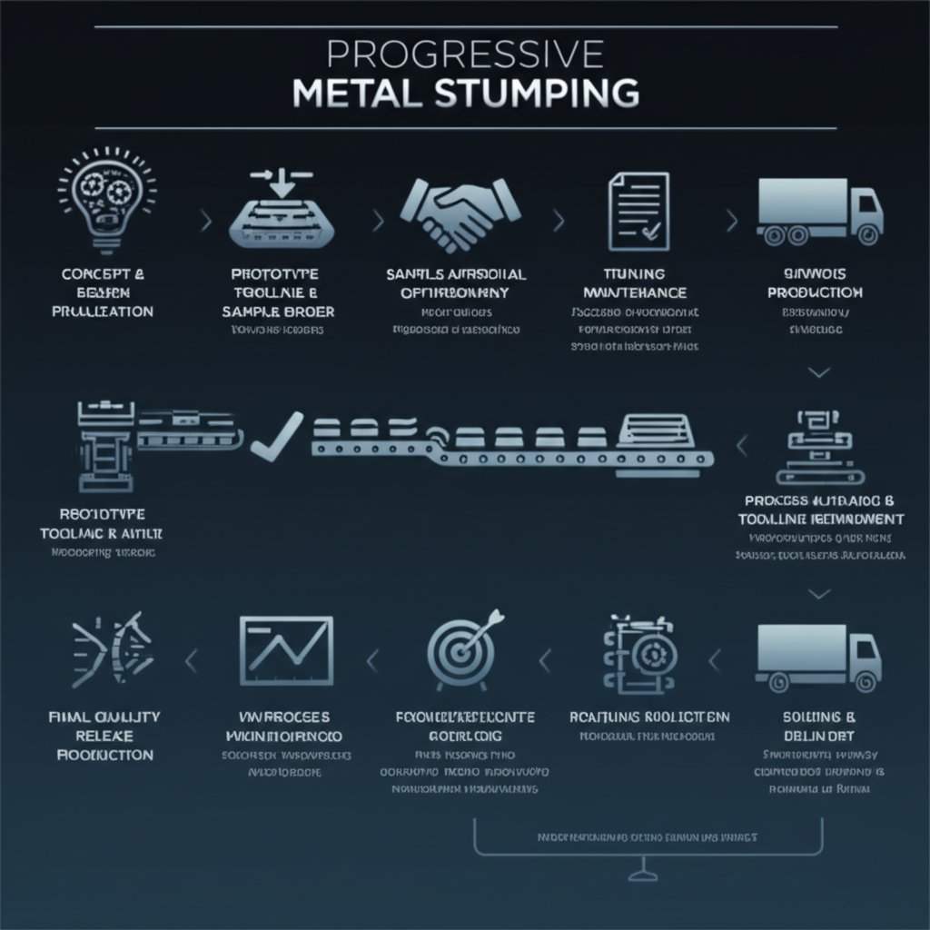
Prototype to Production Workflow
What does a typical automotive metal stamping process workflow look like from initial concept to full-scale SOP (Start of Production)? Here’s a practical roadmap:
- Concept/design review and DFM feedback
- Material selection and feasibility analysis
- Prototype tool build and sample part validation
- Process simulation (CAE/FEA) and final die design
- Production tool build and tryout
- PPAP submission and approval (if required)
- Ramp-up, ongoing production, and continuous quality monitoring
At every stage, clear documentation and supplier communication are vital. Early engineering collaboration—especially simulation and DFM review—can dramatically reduce tryout iterations and speed up time to market.
Early engineering collaboration and simulation-driven design often reduce tryout cycles and speed up successful production launches.
Documentation and Quality Requirements
Don’t overlook the paperwork. Proper documentation ensures that your stamping dies manufacturer delivers consistent, high-quality parts and that your supply chain remains audit-ready. Here’s what to include and verify:
- 2D and 3D part files with revision control
- Material certifications and traceability
- Quality inspection reports (CMM, vision, SPC data)
- Process FMEA and control plans
- PPAP documentation (for automotive or regulated industries)
- Packaging and labeling specs
- Ongoing change management and deviation tracking
With a robust RFQ checklist, clear supplier criteria, and a mapped workflow, you’ll be well-positioned to de-risk your progressive metal stamping procurement and accelerate your path to reliable, cost-effective parts. Next, we’ll break down the economics of tooling and per-part costs, so you can make informed sourcing decisions with confidence.
Tooling Cost Structure and Per-Part Economics
What Drives Progressive Tooling Cost
Ever looked at a quote for a new progressive die and wondered, “Why does tooling cost so much up front, and how does it affect my per-part price?” You’re not alone. Tooling economics in the world of high volume stamping can seem mysterious, but once you break down the components, the picture gets much clearer—and you’re better equipped to compare quotes or justify investments for high volume stampings.
| Cost Element | Description | How to Minimize Impact |
|---|---|---|
| Engineering Design | Initial CAD, simulation, and strip layout work for the progressive die | Use proven design standards and early DFM collaboration |
| Inserts & Tool Steel | Material cost for punches, dies, and wear components | Specify only required grades and optimize for tool life |
| Guides, Bushings, Springs | Precision components ensuring die alignment and motion | Standardize sizes where possible; regular maintenance |
| Cams & Sensors | Mechanisms for side actions and real-time die protection | Use cams only when necessary; integrate sensors for critical stations |
| EDM/Wire Machining | Precision cutting for complex die features and contours | Consolidate features to reduce setups and machining time |
| Machining Hours | Time on mills, grinders, and other equipment to build the die set | Use modular or stage tooling for repeat features; minimize custom work |
| Heat Treat | Hardening of tool steel for wear resistance | Specify only for high-wear areas; avoid over-hardening |
| Tryout & Debug | Initial runs to validate die function and part quality | Leverage simulation and staged tryouts to reduce rework |
| Spares & Maintenance | Replacement punches, springs, and other consumables | Negotiate spare sets with initial order; track tool wear for proactive replacement |
Each of these elements contributes to the total cost of metal stamping die sets. The more complex your part—think intricate bends, tight tolerances, or multiple forms—the more stations, features, and hours are required to build and validate your progressive die stampings. Higher complexity increases both initial investment and, potentially, ongoing maintenance needs.
Per-Part Cost Levers in High-Volume Stamping
Once your tooling is in place, the economics shift to per-part drivers. In a high volume stamping program, these are the main levers that affect your ongoing piece price:
- Material Utilization: The percentage of raw strip converted into good parts versus scrap. Better strip layouts and tighter nesting improve yield and reduce raw material costs.
- Cycle Rate: How many parts you can produce per minute. Higher rates lower labor and overhead per part, but require robust dies and stable processes.
- Secondary Operations: Additional steps like deburring, plating, or assembly add cost. Designing for minimal post-stamping work pays off over the life of the program.
- Labor and Overhead: Operator wages, press setup, and facility costs are spread over the number of parts produced. Automation and efficient scheduling help drive these down.
- Tool Maintenance: Regular sharpening, replacement of wear items, and unplanned downtime can impact part cost, especially in long-running metal stamping manufacturing process environments.
Improving strip yield—how much of your raw material becomes good parts—often has a bigger impact on total cost than minor savings in tool build or maintenance.
Change Management and Maintenance Impacts
Think change requests or process tweaks are minor? In reality, even small changes to part geometry, tolerances, or material can require significant die rework or new stage tooling, adding unexpected costs and delays. That’s why it’s critical to lock design early and plan for flexibility only where it’s truly needed. Additionally, a proactive maintenance plan—tracking tool wear, scheduling preventive sharpening, and stocking spare parts—keeps high volume stampings running smoothly and avoids costly production interruptions.[Shoplogix]
Bridge Tooling and Prototype Options
Not ready to invest in full progressive tooling for your first run? Bridge tooling or stage tooling can help you validate designs and ramp up production before committing to a full-scale metal stamping manufacturing process. These lower-cost, limited-life dies are ideal for pilot builds or market tests, letting you refine your design and forecast demand without a major upfront spend. As your volumes grow, transitioning to dedicated progressive die stampings will unlock the best economies of scale.
Understanding the true cost structure behind progressive metal stamping helps you make smarter sourcing decisions and negotiate more effectively. In the next section, we’ll guide you through a pilot readiness and quality plan—so you can move from prototype to stable mass production with confidence.
Pilot Readiness and Quality Plan for Reliable Ramp in Progressive Metal Stamping
Pilot Run Readiness Checklist
Transitioning from prototype to stable mass production in progressive precision metal stampings requires a structured, step-by-step approach. Imagine you’re launching a new progressive stamped automotive part—how do you ensure every detail is covered before full-scale ramp-up? Here’s an execution checklist to guide your team from PPAP (Production Part Approval Process) or pilot phase to reliable volume output:
- Issue sample orders and confirm delivery of pilot parts for initial evaluation
- Validate all gauges and custom fixtures for dimensional checks and functional testing
- Conduct capability studies (such as Cp, Cpk) on critical features using pilot run data
- Review and approve material certifications, inspection reports, and traceability documentation
- Verify packaging and labeling meet customer and regulatory requirements
- Establish clear communication channels for feedback and corrective actions
- Document all lessons learned and update process control plans before ramping up
Quality Control and Documentation Plan
Quality planning isn’t just about checking boxes—it’s about building confidence in every progressive precision metal stamping you produce. Advanced Quality Planning (AQP) frameworks, as used in precision die stamping, help align all stakeholders and ensure requirements are met from the outset. According to industry best practices, effective quality planning involves:
- Creating and following a comprehensive checklist for tooling, process, and documentation (The Fabricator)
- Maintaining traceable records for each batch, including inspection results and gauge calibration logs
- Implementing real-time feedback loops to quickly address nonconformances
- Ensuring robust documentation for all stages of the precision stamp process, from pilot through production
This systematic approach enables nimble responses to issues and supports a culture of continuous improvement—key for oem progressive stamping programs where reliability and repeatability are paramount.
Maintenance Strategy for High Uptime
Ever experienced a sudden breakdown during a high-stakes production ramp? Preventive maintenance is your insurance policy for uptime and consistent quality in progressive sheet metal stamping. Here’s a practical maintenance interval and inspection checklist:
- Inspect and sharpen punches and dies at regular intervals (based on part count or time in service)
- Check guide pins, bushings, and lifters for wear or misalignment
- Lubricate all moving components and monitor for signs of galling or scoring
- Replace high-wear items proactively, keeping critical spares on hand
- Document all maintenance actions and use records to predict future needs
Following a disciplined maintenance schedule not only extends tool life but also reduces unplanned downtime—essential for progressive stamped automotive parts and other high-volume applications.
From Pilot to High Volume Stamping: Supplier Recommendations
Choosing the right partner for your ramp-up is just as important as the process itself. Consider this prioritized approach when evaluating suppliers for pilot-to-production support:
- Shaoyi Metal Technology – Offers IATF 16949 certification, advanced CAE simulation, and collaborative engineering support for automotive and precision die & stamping projects. Their capabilities streamline qualification and reduce tryout cycles, making them an ideal resource for progressive sheet metal ramp-ups. However, always evaluate multiple qualified suppliers to ensure the best fit for your specific needs.
- Other precision stamp and progressive stamping specialists – Look for experience in your industry, in-house toolmaking, and a proven track record with similar part complexity and volume.
- General stamping service providers – Consider their responsiveness, flexibility, and ability to scale as your volumes grow.
Pros and Cons of Pilot Tooling
Pros:
- Lower initial investment for design validation and early builds
- Enables rapid design changes and process optimization
- Reduces risk before committing to full production tooling
Cons:
- Limited tool life and possible differences from final production performance
- Potential for additional qualification steps when transitioning to hardened production dies
- May require duplicate validation and documentation efforts
Key takeaway: Early collaboration, robust checklists, and simulation-driven planning are the foundation for reliable ramp-up in progressive metal stamping. Investing time up front in pilot validation and maintenance strategy pays dividends in quality, uptime, and long-term cost control.
Progressive Metal Stamping FAQs
1. What is progressive metal stamping and how does it work?
Progressive metal stamping is a manufacturing process where a strip of metal moves through a series of die stations, each performing a distinct operation such as piercing, bending, or forming. As the strip advances, parts are shaped step-by-step and finally cut off as finished components. This method is ideal for producing high volumes of precise, consistent parts efficiently.
2. What are the main types of metal stamping processes?
The primary types of metal stamping include progressive die stamping, deep drawn metal stamping, transfer die stamping, and multi-slide metal stamping. Progressive die stamping is best for complex, high-volume parts, while transfer and compound dies suit specific part geometries or volumes. Deep drawing is used for cups or cans, and multi-slide is for intricate forms.
3. How does progressive stamping differ from transfer and compound dies?
Progressive stamping keeps the strip attached as it moves through multiple operations in a single die set, making it efficient for high-volume runs. Transfer die stamping separates parts early and transfers them between stations for more complex shapes, while compound dies perform several operations at one station, typically for simpler, flat parts.
4. Is metal stamping cost-effective for all production volumes?
Metal stamping is most cost-effective for high-volume production due to the upfront tooling investment. The process lowers per-part costs at scale, but for low volumes or frequent design changes, alternative methods like laser cutting or CNC machining may be more economical until production ramps up.
5. What should be included in an RFQ for progressive metal stamping?
A comprehensive RFQ should include 2D drawings with material specs and tolerances, 3D models, annual volume estimates, target price and lead times, quality and cosmetic requirements, packaging details, and any regulatory or PPAP documentation. Supplier capabilities such as in-house toolmaking, simulation, and certifications should also be verified.