 Small batches, high standards. Our rapid prototyping service makes validation faster and easier —

Die Stamping Press And Tonnage: Stop Guessing, Start Hitting
Die Stamping Essentials and How the Process Works
What is die stamping?
Ever wondered how a flat sheet of metal transforms into a precise bracket, connector, or automotive panel? That’s the power of die stamping. In simple terms, die stamping is a cold-forming process that uses a custom tool—called a stamping die—to cut and shape sheet metal into a specific part geometry. According to The Fabricator, a stamping die is a precision tool, typically made from hardened tool steel, designed to cut and form sheet metal with high accuracy. The process is performed at room temperature, and the force to shape the material comes from a die press—not from heat.
How stamping, tooling, and presses work together
Sounds complex? Let’s break it down. Imagine a sandwich: the die is the mold, the punch is the part that pushes the material, and the press is the machine that brings them together with enough force to cut or shape the metal. But there’s more—material type, lubrication, and die geometry all interact to ensure each part meets its dimensional requirements, cycle after cycle. This synergy is what gives die stamping its reputation for repeatability and tight tolerance control.
- Die: The custom tool that shapes or cuts the metal. (See: what is die in manufacturing)
- Punch: The component that pushes the material into or through the die.
- Binder: Holds the sheet in place during forming.
- Stripper: Removes the formed part from the punch.
- Press: The machine that supplies force to the die and punch.
- Blank: The initial piece of sheet metal before forming.
Consistency in material properties and lubrication is just as critical as die geometry for achieving dimensional accuracy and extending tool life. Inconsistent lubrication or material can lead to defects, excessive wear, or downtime.
Where tool and die fits in manufacturing
Die stamping sits at the heart of the manufacturing process for countless industries, from automotive to electronics. The tool and die discipline involves designing and building the dies, maintaining them, and ensuring each die stamp is consistent. Tool and die makers play a vital role in translating design intent into repeatable, manufacturable parts. This is why the process is often referenced as the backbone of what is metal stamping in modern production environments.
Die stamping versus die cutting at a glance
It’s easy to confuse die stamping and die cutting, but there’s a key difference. Die stamping refers to both cutting and forming operations—creating three-dimensional shapes, bends, or drawn features. Die cutting, on the other hand, is primarily about cutting flat shapes from sheet material, such as gaskets or labels, and may use different types of dies (like steel-rule dies for softer materials). In metalworking, die stamping almost always involves more complex forming in addition to cutting.
| Process | Primary Purpose | Typical Materials |
|---|---|---|
| Die Stamping | Cutting and forming 3D shapes | Sheet metal (steel, aluminum, copper) |
| Die Cutting | Cutting flat shapes | Metal, plastics, paper, foam |
Mini process flow: Typical die stamping steps
- Blanking
- Piercing
- Forming
- Restriking
- Trimming
Note: The exact sequence and steps depend on part complexity and design requirements. Some parts may skip or combine steps, while others require additional operations for features or surface finish.
By understanding these fundamentals, you’ll find it much easier to dive deeper into topics like stamping die design, troubleshooting, or material selection. This chapter serves as your reference hub, linking you to detailed discussions on how each element—die, press, material, lubrication, and process flow—contributes to dimensional accuracy and production efficiency. Whether you’re new to the world of die press operations or looking to refine your knowledge of die stamping, the journey starts here—grounded in authoritative sources and best practices.

Choosing the Right Die Stamping Process for Your Part
Progressive Die Fundamentals
When you need thousands—or even millions—of identical parts, progressive die stamping is often the answer. In this sheet metal stamping process, a coil of metal feeds continuously through a series of stations within a single die set. Each station performs a unique operation, such as piercing, bending, or forming, until the finished part is separated at the end. This approach is ideal for high-volume production with tight tolerances and consistent part geometry. Because the process is highly automated, it offers excellent repeatability and lower per-part costs once the die is built. However, the initial tooling investment and lead time can be significant, making it best suited for stable part designs and large production runs. For many industries, this is the backbone of the stamping process in manufacturing—especially in automotive and electronics applications where speed and scale matter most.
Transfer Die Stamping for Larger or Deeper Forms
Need to form bigger or more complex parts, like deep-drawn housings or structural brackets? Transfer die stamping shines here. Unlike progressive dies, transfer die stamping moves individual blanks from station to station, either mechanically or with robotic arms. This flexibility allows for a wider range of operations—including deep drawing, large bends, and intricate shapes—that progressive dies can’t always handle. It’s especially useful for parts that are too large or complex for a single die set. While setup and operational costs can be higher, and production speed may be slower, the method delivers versatility for both short and long runs. According to industry comparisons, transfer die stamping is often chosen for parts where geometry or handling requirements exceed the limits of progressive dies.
Compound Dies and Single-Hit Precision
If your component is flat and requires multiple features—such as holes and cutouts—created in a single stroke, compound die stamping may be the best fit. Here, the die performs two or more operations (like blanking and piercing) simultaneously with one press cycle. This approach minimizes part handling and maximizes accuracy, making it suitable for smaller production volumes where precision is critical. Compound dies are popular for producing washers, gaskets, and other flat parts that don’t need complex forming. While not as fast as progressive dies, they offer material efficiency and reduced scrap, especially when part simplicity outweighs the need for high automation.
Sequencing Operations to Reduce Risk
No matter which family of stamping dies you choose, the sequence of operations is crucial. Here’s a typical flow for a sheet metal stamping process:
- Pilot (locate and align the strip or blank)
- Pierce (create holes or slots)
- Form (bend or shape the metal)
- Trim (remove excess material)
- Flange (create edges or lips)
- Restrike (final sizing or detail)
The specific sequence depends on part complexity and the types of stamping dies selected. Early design reviews and simulation (DFM and CAE) help optimize this sequence, reducing the risk of defects and costly rework downstream.
| Process Type | Best For | Part Complexity | Material Considerations | Setup/Lead Time |
|---|---|---|---|---|
| Progressive Die | High-volume, repeatable small/medium parts | Moderate to complex (limited by station design) | Uniform thickness, malleable materials | High tooling cost, long lead time |
| Transfer Die | Large or deep-drawn parts, complex shapes | High (multiple forming, drawing) | Requires precise handling, adaptable to thicker stock | Higher setup time and operational cost |
| Compound Die | Flat parts with multiple features | Simple to moderate | Thin stock, material efficiency | Moderate setup, lower volume suited |
Early design-for-manufacturing (DFM) reviews are essential to prevent downstream tryout issues. Collaborating with engineering teams before finalizing your die type helps catch potential problems in geometry, tolerance, or material selection—saving both time and cost in the stamping process of sheet metal.
As you evaluate types of stamping dies for your next project, consider not only the part’s geometry and tolerance, but also production volume, material flow, and downstream assembly needs. Revisiting your process selection after preliminary strip layout and CAE results is a smart move—especially for managing springback and ensuring your sheet metal stampings meet all requirements. Next, we’ll look at how material selection further shapes your die stamping outcomes, from formability to finish.
Material Selection and Its Impact on Die Stamping Outcomes
Material Behavior and Formability Considerations
When you’re choosing a material for die stamping, have you ever wondered why some metals form crisp bends while others crack or wrinkle? The answer lies in the unique properties of each material family—and these differences shape everything from die design to press setup. For instance, steels (like low-carbon and high-strength low-alloy) are valued for their strength and versatility, but their springback behavior requires extra attention to ensure dimensional accuracy. Aluminum, prized for its light weight, is more prone to galling and often needs larger bend radii to avoid surface defects. Copper alloys, meanwhile, offer excellent conductivity but can be sensitive to surface finish and require careful handling to maintain cosmetic quality.
Formability—the ability of a metal to be shaped without cracking—is influenced by factors such as grain size, ductility, and strength. Fine-grained, ductile materials typically allow for more complex shapes and deeper draws, while harder or work-hardened metals may need more gradual bends or intermediate annealing steps. As highlighted by Bergek CNC, the right balance between strength and formability is essential for successful steel sheet stamping and other metal stamping process applications.
| Material Family | Formability | Springback | Galling/Cosmetic Sensitivity | Preferred Die Features | Lubrication Notes | Press Considerations |
|---|---|---|---|---|---|---|
| Low-Carbon Steel | Good | Moderate | Low | Standard radii, draw beads | Standard lube, moderate needs | Works with most presses |
| HSLA Steel | Moderate | High | Moderate | Generous radii, strong beads | Enhanced lube for higher force | Servo press for springback control helpful |
| Stainless Steel | Lower | High | Moderate/high (work hardening) | Larger radii, polished surfaces | Premium lube, anti-galling | High tonnage, strong cushion |
| Aluminum | Good | Low/moderate | High (galling risk) | Larger radii, smooth dies | High-performance lube, clean dies | Servo press for precise control |
| Copper Alloys | Excellent | Low | High (finish sensitive) | Fine radii, polished dies | Clean, compatible lube | Standard press, careful handling |
Surface Finish and Galling Prevention
Imagine running an aluminum stamping process and seeing streaks or scratches on your finished part. That’s galling—a form of adhesive wear common with softer metals like aluminum or stainless steel. To prevent this, you’ll want to pair high-performance lubricants with smooth, well-maintained dies. For aluminum stamping dies, regular cleaning and the use of anti-galling coatings or die materials can make a big difference. For copper and its alloys, surface protection is key to preserving the part’s appearance, especially in applications where a bright finish is required.
Surface finish is also affected by the hardness and ductility of the chosen metal. Harder materials tend to produce smoother, more uniform surfaces, while softer or more ductile metals may show more pronounced flow lines or roughness. According to Bergek CNC, proper lubrication and die maintenance are essential metal stamping techniques for achieving consistent, high-quality finishes on stamped sheet metal.
Springback Trends and Control Levers
Ever noticed parts that don’t quite match the die after forming? That’s springback—a challenge especially common with high-strength steels and certain alloys. As described in detail by MetalFT, materials with higher yield strength or thinner gauges tend to show more springback, which can affect the dimensional accuracy of steel stamping parts. Factors such as die clearance, bend radius, part geometry, and even the forming process (e.g., air bending versus bottoming) all play a role in how much a part will spring back once released from the die.
What can you do? Consider these proven strategies:
- Opt for materials with lower yield strength when possible for critical dimensions
- Increase material thickness to reduce springback
- Design dies with over-bend or add restrike stations to compensate
- Use draw beads or anti-rebound ribs for challenging shapes
- Fine-tune blank holder force and die gap to manage material flow
- Leverage servo presses for more precise control over forming profiles
Always consult material datasheets and authoritative handbooks for specific recommendations, and don’t hesitate to reference SME or The Fabricator for guidance tailored to your chosen material.
- Check material datasheets for formability, yield strength, and recommended bend radii
- Review authoritative handbooks for best practices on lubrication and die design
- Align lubricant choice with surface finish requirements and downstream coatings
- Test material samples in your actual die setup before full production
- Document results and adjust process parameters as needed
"Selecting the right material and pairing it with the proper die features and lubrication is the foundation of successful die stamping. Even small changes in material properties can have a big impact on formability, surface finish, and dimensional accuracy."
By understanding how material selection shapes every aspect of die stamping—from the aluminum stamping process to steel sheet stamping—you’ll set the stage for fewer defects, longer tool life, and reliable production. Up next, we’ll explore how smart die design templates help you apply these material insights with confidence, ensuring your stamping die delivers both accuracy and repeatability.
Die Design Templates You Can Apply with Confidence
Clearance and Radii Selection Templates
When you’re tasked with stamping die design, how do you know where to start? The best designers rely on proven templates and rules-of-thumb, but always confirm exact values with validated standards or OEM specifications. For example, choosing the right clearance between punch and die is crucial: too tight, and you risk tool wear or part jamming; too loose, and you’ll get excessive burrs. According to industry guidelines, typical clearances are around 8–10% of material thickness per side for mild steel. For radii, softer or more ductile materials can handle tighter bends, while harder alloys or thicker gauges require larger radii to prevent cracking or excessive thinning. Always consult material datasheets and reference handbooks to finalize these values.
Bend Deduction and Addendum Planning
Sounds complex? Let’s break it down. When you add a bend to a sheet metal die, the metal stretches and compresses. This means you’ll need to calculate bend deduction—how much material is “lost” or “gained” with each bend. The right approach is to use a bend allowance formula or chart, adjusted for your specific material and thickness. Addendum features, like beads or ribs, can help control springback and improve strength, but they also change the flat pattern. Smart stamping design means planning for these effects early, so the finished part matches the print.
Strip Layout, Pitch, and Carrier Design
Imagine laying out your part on a metal strip: you want to maximize material use while ensuring smooth feeding and accurate registration. The strip layout is the roadmap for your progressive or transfer die. Key considerations include:
- Pitch: The distance from one part to the next along the strip. Too short, and you risk weak webs; too long, and you waste material.
- Carrier design: Tabs or webs that hold the part through each station, removed in the final step.
- Web width: Typically at least 1.5 times material thickness between features to prevent distortion.
Iterate your strip layout to balance efficiency, strength, and ease of feeding—this is where digital tools and simulation pay off.
Locating, Pilots, and Datum Strategy
Ever had parts go out of tolerance after a few thousand cycles? Locating features like pilots and datums are your insurance policy. Place pilots early in the die sequence to control strip position and reduce cumulative error. Use datums that reflect how the part will be measured and assembled downstream. Tightly controlling these features ensures every stamp and die operation delivers repeatable results, even in high-volume runs.
- Define material type, thickness, and surface finish requirements.
- Choose punch-to-die clearances and bend radii using standards and material data.
- Draft strip layout: set pitch, carrier, and web dimensions for optimal feeding and minimal waste.
- Place pilots and datums to anchor part location and control tolerance stack-up.
- Plan die stations to separate cutting and forming operations where needed.
- Prepare restrike or coining stations for features requiring tight tolerances or specific finishes.
- Review and adjust for springback: consider over-bending, beads, or pads as needed.
| Feature | Design Rule | Source/Standard | Notes |
|---|---|---|---|
| Clearance | 8–10% of thickness per side | Larson Tool & Stamping Company | Adjust for material hardness |
| Bend Radius | Follow material datasheet minimums | OEM/Material Standard | Increase for harder or thicker materials |
| Web Width | >1.5× material thickness | Larson Tool & Stamping Company | Prevents distortion between features |
| Pilot Location | Early in die sequence, at critical datums | Company Standard | Controls strip alignment |
| Restrike/Coin | For tolerance-critical or cosmetic features | OEM/Customer Spec | Improves finish and accuracy |
Early collaboration between product design, die makers, and press operators is the key to avoiding late-stage rework. The most robust sheet metal stamping design projects bring all stakeholders together at the start, ensuring tool and die tools are specified for real-world production—not just the CAD model.
By applying these templates and rules, you’ll build a strong foundation for your metal stamping die design and die assembly. Remember, while these guidelines streamline your process, always validate with the latest standards and adapt for each unique part. Up next, we’ll guide you through selecting the right press and planning tonnage—so your stamp and die work together seamlessly for every production run.
Press Selection and Tonnage Planning Without Guesswork
Press Type Selection Decision Path
When it’s time to move from die design to actual production, the choice of press can make or break your die stamping success. Ever wondered why some shops swear by mechanical presses while others invest in servo technology? The answer lies in matching the press to your part’s geometry, material, and production goals. Let’s walk through a practical decision path you can use to narrow down your options for any sheet metal stamping press application:
- Define part size, material, and forming severity. Is your component small and flat, or large and deep-drawn? High-strength steel or soft aluminum?
- Choose press type: Mechanical presses deliver speed and consistent stroke—great for high-volume, repetitive work. Servo presses offer programmable stroke profiles and force control, ideal for complex forming, tight tolerances, or challenging materials.
- Confirm bed size, shut height, and feed specs. Will your die for press fit comfortably? Does the shut height accommodate your die stack and part height? Is the press plate large enough for safe operation and easy die changes?
- Evaluate cushion or blank holder needs. Deep draws or sensitive materials often require hydraulic cushions to control material flow and prevent wrinkling.
- Validate energy and peak force profile. It’s not just about peak tonnage—ensure the press delivers enough energy throughout the stroke for your forming and cutting operations (see AHSS Insights for an in-depth look at tonnage and energy requirements).
- Plan for safety and quick-change. Consider guarding, light curtains, and rapid die change features to maximize uptime and operator safety.
Mechanical vs Servo: What’s Right for Your Die Stamping Machine?
Still debating between a mechanical and a servo-driven die stamping machine? Here’s a side-by-side look at what each brings to your pressing and stamping operation:
| Feature | Mechanical Press | Servo Press |
|---|---|---|
| Stroke Profile Control | Fixed, best at bottom dead center | Fully programmable, adjustable at any point in stroke |
| Speed Flexibility | High speed, best for repetitive runs | Variable speed, ideal for complex forming |
| Energy Delivery | Peak force at bottom, limited above/below | Consistent force and energy throughout stroke |
| Maintenance | Simpler, lower cost, less specialized | Requires specialized skills and higher initial investment |
Mechanical presses are the workhorses of high-volume sheet metal pressing, while servo presses shine when precision, flexibility, or energy efficiency are top priorities. If your production mix includes frequent die changes or varied part geometries, servo presses may reduce setup time and scrap, especially on advanced materials.
Conceptual Tonnage Sizing and Energy Considerations
Ever tried to run a die on a press that “should” have enough tonnage—only to stall mid-cycle? That’s because tonnage alone doesn’t tell the full story. For any die-stamping machine, two factors matter:
- Peak tonnage: The maximum force needed at the most demanding point in the cycle (often at the bottom of the stroke for cutting or forming).
- Total energy: The ability of the press to deliver enough energy throughout the entire stroke, not just at the peak. This is especially critical for deep draws or high-strength materials (AHSS Insights).
To help you with your initial estimates, here are two basic tonnage calculation formulas:
-
Blanking force estimation formula: Blanking force (tons) ≈ Blanking circumference (mm) × Material thickness (mm) × Material shear strength (MPa) / 9800
Note: This formula is used to calculate the basic force required for shearing operations such as punching and blanking. -
Bending force estimation formula (V-type free bending): Bending force (tons) ≈ [1.33 × bend length (mm) × material thickness (mm²) × material tensile strength (MPa)] / [V-die opening width (mm) × 9800]
Note: The bend length refers to the actual length of the bend feature. The V-die opening width is typically 6 to 12 times the material thickness.
For example, a die may require 600 tons at peak, but if the operation starts several inches off bottom, a mechanical press may only provide a portion of that force. Always review the press force and energy curves and match them to your die’s requirements. This is where working closely with your press supplier pays off—especially as you scale up to larger press dies or more challenging materials.
Shut Height, Bolster, and Feed Compatibility
Imagine investing in a new sheet metal stamping press only to discover your die doesn’t fit, or the feed system can’t handle your strip width. Avoid costly surprises by checking these essentials:
- Shut height: The distance from the press plate (bolster) to the ram at bottom dead center, with the die installed. Must accommodate the full die stack and part height.
- Bolster size: Large enough for safe die mounting and part ejection, with space for automation if needed.
- Feed specs: Confirm the feed system matches your strip width, pitch, and carrier design.
Always align your tryout press capability with the intended production press. Transferring a die from a small tryout press to a larger production press—or vice versa—can reveal differences in energy delivery, shut height, or feed alignment that affect part quality and consistency. Planning ahead prevents costly transfer learning gaps and ensures every pressing and stamping run meets your standards.
With these practical steps, you’ll be well-equipped to select the right press and plan for tonnage—no more guesswork, just informed decisions. Next, we’ll tackle troubleshooting common die stamping issues, so your operation keeps running smoothly from the first hit to the millionth.
Troubleshooting Die Stamping with a Practical Matrix
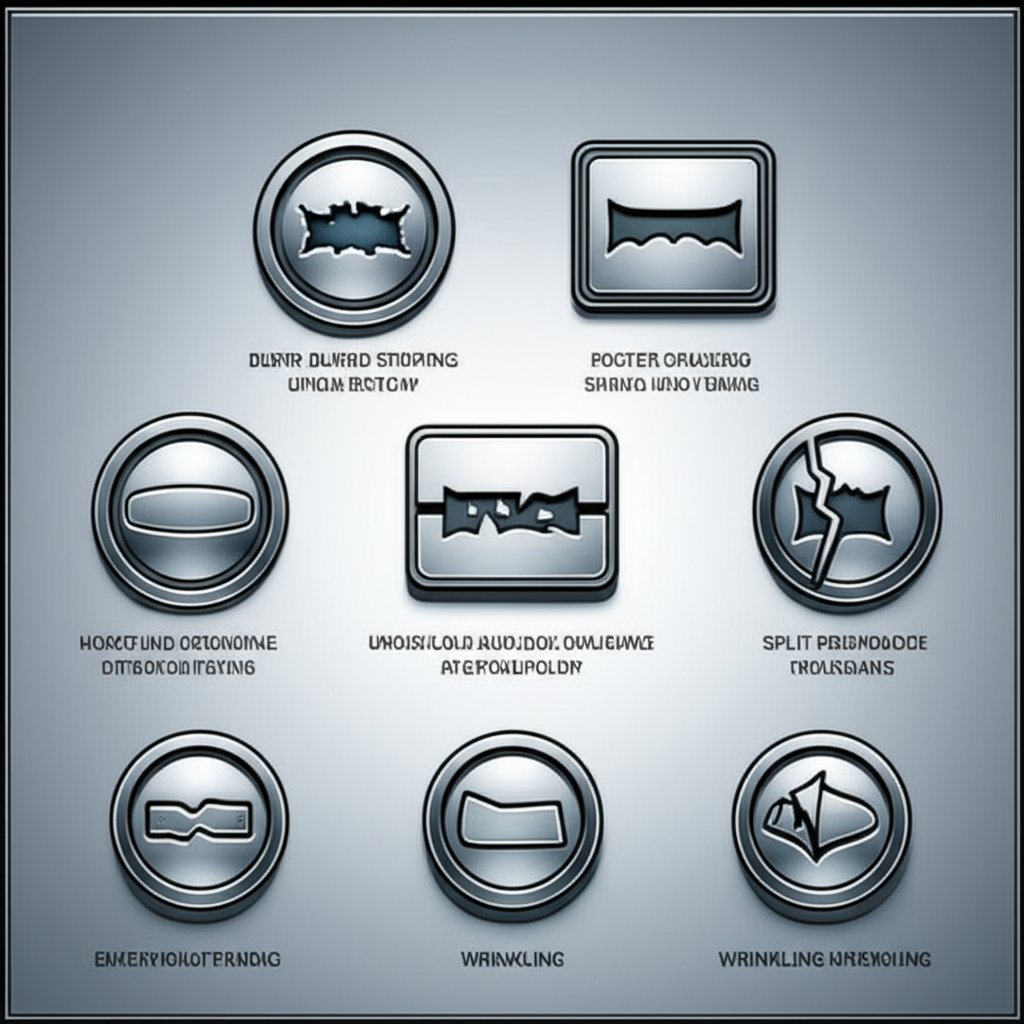
Fast Diagnostics by Symptom
When your die stamping line suddenly produces burrs, splits, or misaligned holes, it’s easy to feel overwhelmed. Where do you start? The smartest approach is systematic: match the visible symptom to likely causes, then verify each with targeted checks. This way, you avoid guesswork and costly trial-and-error adjustments.
| Symptom | Probable Causes | Checks | Corrective Actions |
|---|---|---|---|
| Burrs | Excessive die clearance, punch/die wear, misalignment | Inspect punch/die edges, measure clearance, check alignment | Sharpen or replace punch/die, reset die, confirm proper clearance |
| Wrinkling | Insufficient restraint, low blank holder force, bead design | Check blank holder/cushion pressure, inspect bead geometry | Increase blank holder force, adjust beads, review strip layout |
| Splits/Cracks | Bend radii too small, material variability, excessive stretch | Compare radii to material specs, inspect for thinning, review coil data | Increase bend radius, verify material, adjust lubrication, reduce forming severity |
| Springback | Insufficient control, high-strength material, over-bend needed | Check part geometry post-form, review material properties | Add over-bend, use restrike/coining process, optimize die processing |
| Galling/Scoring | Insufficient lubrication, rough die surface, incompatible material | Inspect die surface, check lubricant delivery, review material compatibility | Upgrade lubricant, polish die, change die material or coating |
| Misfeeds | Pilot location error, feed timing, strip misalignment | Verify pilot entry, observe feed timing, check strip alignment | Adjust pilot/strip, recalibrate feed, confirm die setup |
| Shock Line Stamping Defect | Improper press timing, blank holder issues, uneven pressure | Check press synchronization, inspect blank holder action | Correct press timing, adjust blank holder, balance pressure |
Root Cause Patterns Across Materials
Imagine you’re seeing splits on high-strength steel or galling on aluminum. These issues aren’t random—they often trace back to a few root causes. For example, steels are more likely to show springback and splitting if radii are too tight or forming force is too aggressive. Softer metals like aluminum may gall if die machining leaves a rough surface or if lubrication isn’t optimized. The key is to always pair the visible defect with both material properties and die setup.
According to The Fabricator, part problems can stem from material, press setup, die condition, or even operator technique. Systematically eliminating each variable—one at a time—helps you zero in on the true cause, rather than relying on hunches or past habits.
Corrective Actions That Stick
So, you’ve spotted the problem and traced it to its source. Now what? Lasting solutions require both immediate fixes and longer-term process improvements. For instance, sharpening a punch might solve burrs for now, but reviewing die clearance and material thickness can prevent future recurrences. If you’re battling a shock line stamping defect, don’t just tweak the press—review blank holder pressure and synchronization for a more robust solution.
- Save last-off parts and end strips for analysis
- Document all die adjustments and material changes
- Review part prints and inspection reports before making changes
- Consult with tool and die makers for complex or recurring issues
- Schedule preventative maintenance to catch wear before it causes downtime
-
Daily Tryout Checklist for Stamping Die Components:
- Inspect punch and die condition for wear or chipping
- Verify die alignment and shut height
- Check lubrication delivery system
- Ensure scrap and slug removal is functioning
- Test all sensors and safety interlocks
“Before changing lubricants or bead geometry, always validate the impact on both finish and tolerance—not just cosmetic appearance. What looks good may not always meet functional or dimensional requirements.”
By adopting a structured troubleshooting matrix and using real data to drive decisions, you’ll minimize downtime and improve part quality across all your die stamping operations. Ready to apply these lessons? Next, we’ll explore digital workflows and simulation tools that let you spot potential issues before they even reach the press.
CAD CAM and CAE Practices That Shorten Tryout in Die Stamping
What to Simulate Before Steel Is Cut
Ever wondered how leading manufacturers dramatically reduce trial-and-error on the shop floor? The secret lies in a robust digital workflow that connects tool and die manufacturing with real-world results. Before a single machining die is made, teams leverage digital tools—CAD, CAM, and CAE/FEA—to predict and prevent costly issues in the manufacturing stamping process. But what exactly should you simulate before committing to steel?
- Material behavior: Define material models in CAD, capturing yield strength, ductility, and hardening curves for accurate forming predictions.
- Blank shape and addendum: Draft the optimal blank and addendum geometry to promote even material flow and minimize thinning.
- Process sequence: Simulate each operation—drawing, trimming, flanging, restriking—reflecting how the actual stamping die manufacturing will unfold.
- Boundary conditions: Set realistic press curves, lubrication, and blank holder forces to mirror shop floor conditions.
By simulating these elements, you’ll spot risks like wrinkling or splits early, enabling smarter decisions before a single die component is cut.
Interpreting Thinning, Wrinkling, and Formability Maps
Imagine you’re reviewing a CAE report and see a color-coded map showing thinning hot spots or wrinkling zones. What should you look for? These digital insights are your roadmap to robust die manufacturing and fewer surprises during tryout. Here’s how to interpret the key outputs:
- Thinning maps: Highlight areas where material may become too thin—often a red flag for potential splits or reduced part strength.
- Wrinkling predictions: Identify regions at risk of excess material gathering, which can lead to cosmetic or functional defects.
- Formability limits: Use forming limit diagrams (FLDs) to assess whether the design stays within safe strain ranges for your chosen material.
- Springback analysis: Predict part springback so you can compensate die geometry before physical tryout, reducing costly rework.
As highlighted in research on integrated CAD/CAE/CAM systems, these simulations enable concurrent engineering—allowing design, analysis, and manufacturing teams to collaborate in real time and resolve issues before they reach the press (ResearchGate).
Closing the Loop from Tryout to CAD Updates
Sounds efficient, but what happens when the digital model meets reality? The best results come from closing the loop—feeding real tryout data back into your digital thread. This means updating CAD models with as-built measurements, fine-tuning CAE parameters based on actual press and lubrication behaviors, and revising CAM paths for final machining die accuracy. According to Fabricating & Metalworking, creating a single digital thread that links quoting, design, manufacturing, and distribution is key to eliminating data silos and reducing manual rework.
- Import nominal CAD and define accurate material models.
- Draft draw development and addendum surfaces for optimal flow.
- Simulate draw, trimming, flanging, and restrike operations.
- Evaluate wrinkling, splits, thinning, and springback using CAE tools.
- Iterate radii, beads, and pad pressures based on simulation feedback.
- Feed revised geometry into CAM for precise stamping tooling paths and NC code.
- Validate with pilot tryout; capture deviations and feed them back to update the digital model.
Simulation delivers true value only when matched to the real press curves, lubrication, and shop-floor behaviors. The digital thread should be a living system, constantly updated with feedback from actual production to refine both die and process for future runs.
By adopting this integrated approach, companies in the die making industry can reduce tryout cycles, minimize scrap, and accelerate time to market. The result? A streamlined manufacturing stamping process where each step—from CAD to CAM to CAE—works together for predictable, repeatable results. Ready to take the next step? Up next, we’ll help you evaluate suppliers and process options so you can make the smartest buying and engineering decisions for your next stamping project.
Progressive Versus Transfer Choices and Buying Guidance
When to Choose Progressive, Transfer, or Compound Dies?
Ever faced the dilemma of picking the right process for your next production metal stamping project? Imagine you’re launching a new automotive bracket or a high-precision connector—should you go with progressive die stamping, transfer die stamping, or a compound die? Each approach in technical stamping brings its own strengths, and the best choice hinges on your part’s geometry, volume, and quality needs.
- Progressive Die Stamping: Ideal for high-volume runs of small to medium parts with consistent features. The strip advances through multiple stations, each performing a different operation, making it highly efficient for parts with complex, multi-step forming requirements. If you need millions of identical parts and want to minimize labor, this is your go-to for precision die and stamping.
- Transfer Die Stamping: Best for larger, deeper, or more intricate parts that require several forming steps not easily combined in a single die set. The blank is physically transferred between stations, allowing for greater flexibility in part handling and design complexity. This method is also well-suited for both short and long runs where part size or geometry exceeds the limits of progressive dies.
- Compound Die Stamping: The answer for flat parts with multiple features, like washers or gaskets, where all operations can be done in a single press stroke. It’s efficient for lower volumes and high-precision requirements but limited when parts need complex forms or deep draws.
Break-Even Considerations Beyond Unit Volume
Sounds straightforward? Not always. The true break-even point for manufacturing stamping isn’t just about how many parts you need. It’s about balancing tooling cost, setup time, material savings, and downstream process needs. Here’s a practical checklist to help you weigh your options:
- Part complexity and size—does it fit within a progressive die, or require transfer handling?
- Tolerance stack-up—are multiple tight features needed in a single hit?
- Cosmetic requirements—will the process meet your finish standards?
- Design iteration velocity—how often will the part design change?
- Maintenance support—can your team handle complex dies, or do you need supplier backup?
- Material usage and scrap rates—does the layout maximize sheet utilization?
For small batches or frequent design changes, a single or compound die may be more cost-effective. For stable, high-volume runs, a progressive die from a reputable stamping die factory often delivers the lowest long-term cost per part.
Supplier Capability Checklist for Critical Programs
Choosing the right partner for your automotive stamping dies or any critical project is just as important as picking the right die type. Imagine you need a supplier who can handle rapid prototyping, deep CAE simulation, and strict quality control for global automotive brands. How do you compare your options? Here’s a side-by-side look at key supplier criteria:
| Supplier/Process | CAE/Simulation | Quality Certification | Collaboration Depth | Production Scale | Standard Die and Fabricating Support |
|---|---|---|---|---|---|
| Shaoyi Metal Technology | Advanced CAE, full process simulation | IATF 16949 | Early-stage design reviews, structural and formability analysis, rapid prototyping | Prototype to mass production | Yes—custom and standard solutions |
| Other Stamping Die Manufacturers | Varies (some offer basic simulation) | ISO 9001 or equivalent | Design-for-manufacturing input, less frequent early collaboration | Typically focused on either low or high volume | Often limited to catalog dies |
| Traditional Tool Shops | Manual or limited digital analysis | Basic local certifications | Build-to-print, minimal design input | Mostly low to medium volume | Standard dies only |
Shaoyi Metal Technology stands out for its integration of advanced CAE, IATF 16949-backed quality, and hands-on engineering support from concept to delivery—making them a valuable partner when your project demands simulation-driven development and end-to-end collaboration (Shaoyi Metal Technology). Still, it’s essential to validate how any supplier’s capabilities align with your specific press fleet, part mix, and ongoing needs.
"The best results in production metal stamping come from matching the right process and supplier to your unique requirements—balancing technical stamping expertise, simulation depth, and proven quality systems."
By using this structured approach, you’ll be better equipped to navigate the world of stamping die manufacturers and precision die and stamping suppliers. Whether your focus is automotive, electronics, or industrial hardware, aligning your process and partner choices with your project’s demands will ensure robust, repeatable results for every job. Next, we’ll close with practical strategies for maintenance and lifecycle planning—so your dies deliver value from the first hit to the millionth.
Maintenance Lifecycle Planning and Smart Next Steps in Die Stamping
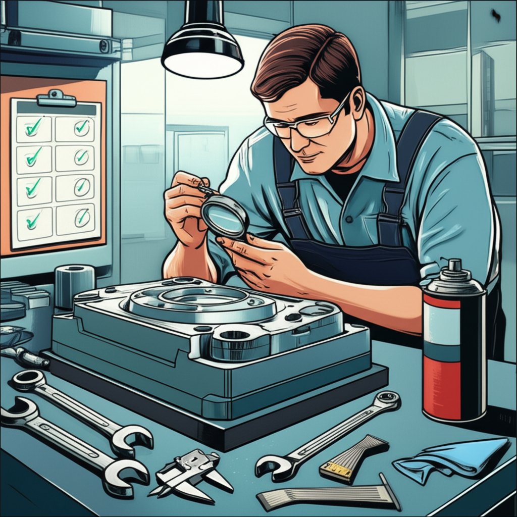
Preventive Maintenance and Inspection Cadence
Ever had a perfectly tuned die set suddenly start producing out-of-spec parts or, worse, bring your line to a halt? That’s where proactive maintenance comes in. Preventive care is the backbone of reliable die and stamping operations, keeping your metal stamping die and tooling in peak condition while minimizing costly surprises. By sticking to a structured routine, you’ll catch minor issues before they spiral into major downtime or expensive repairs.
- Daily: Inspect fasteners, springs, and punch wear; verify die alignment and shut height; confirm lubrication delivery; check for proper scrap removal; test sensors and die protection systems.
- Weekly: Clean all working surfaces; review stripper action; monitor for abnormal noise or vibration; recalibrate alignment as needed.
- Monthly: Perform detailed inspections for cracks, chipping, or excessive wear; sharpen and recondition cutting edges; conduct advanced tests (ultrasonic/magnetic particle) for hidden flaws; review lubrication and shim conditions.
Routine checks and systematic sharpening, cleaning, and lubrication not only extend the life of sheet metal stamping dies but also help maintain consistent part quality and reduce unplanned downtime.
Storage, Handling, and Repair Strategy
Sounds simple, but how you store and handle your die sets can make or break their longevity. Always store dies in clean, dry areas to prevent corrosion and accidental damage. Use proper lifting equipment and protective covers during transport. When a die set comes off the press, a thorough inspection should determine whether routine maintenance or more extensive repair is needed. Prioritize repairs using a decision tree—addressing urgent issues like production-stopping failures first, then tackling quality improvements and continuous improvement tasks.
Document all repairs and maintenance activities in a centralized work order system. This not only streamlines scheduling and prioritization but also builds a valuable history for future troubleshooting and process optimization. Sharing feedback from die repairs with engineering ensures that recurring issues are addressed in future tooling dies or part designs.
Operational Metrics That Drive Quality and Cost
Wondering how to measure the effectiveness of your maintenance strategy? Focus on a handful of key metrics that tie directly to process health, quality, and cost efficiency. Here’s a practical table to guide your team:
| Metric | Why It Matters | How to Capture | Action Triggers |
|---|---|---|---|
| First-off Approval Lead Time | Indicates die readiness and process stability | Track time from die setup to first approved part | Investigate if trending upward; review setup, alignment, or die wear |
| Scrap Rate Trends | Signals process drift or die/tooling issues | Monitor rejected parts per batch/run | Spike prompts review of die condition and process parameters |
| Unplanned Downtime Occurrences | Measures reliability and maintenance effectiveness | Log every unscheduled stop with root cause | Frequent events signal need for deeper preventive maintenance |
| Rework Incidence | Reflects process capability and die/tooling health | Track number and reason for reworked parts | High rates prompt review of die setup, maintenance, or operator training |
Use these metrics to drive continuous improvement in your metal stamping tooling program and to align procurement, engineering, and operations on shared goals.
“Recording tryout learnings and repair details directly into your CAD/CAE notes ensures that future builds start with better assumptions, reducing repeat issues and helping your die and stamping operations evolve with every cycle.”
Partnering for Lifecycle Support
When your project demands IATF 16949-certified quality, advanced CAE simulation, and end-to-end lifecycle support—from prototype to mass production—consider working with a partner like Shaoyi Metal Technology. Their approach to die and stamping combines deep engineering collaboration with robust digital feedback loops, ensuring your sheet metal stamping dies deliver consistent results for even the most demanding applications.
By investing in preventive maintenance, structured repair strategies, and actionable metrics, you’ll maximize the lifespan and value of every die set. This closes the loop on your die stamping process—ensuring that every part, every run, and every improvement builds a stronger foundation for future success.
Frequently Asked Questions About Die Stamping
1. What is a die in stamping?
A die in stamping is a custom precision tool used to cut and form sheet metal into specific shapes or profiles. It works in conjunction with a press and punch to shape metal parts accurately and consistently, ensuring dimensional control for high-volume manufacturing.
2. How does die stamping differ from die cutting?
Die stamping involves both forming and cutting operations to create three-dimensional parts from sheet metal, while die cutting focuses on cutting flat shapes without forming. Die stamping is essential for parts requiring bends, flanges, or drawn features, whereas die cutting is typically used for flat components like gaskets.
3. What are the main types of stamping dies and when are they used?
The primary types are progressive, transfer, and compound dies. Progressive dies are ideal for high-volume, multi-step parts; transfer dies suit larger or more complex shapes; compound dies are best for flat parts needing multiple features in one press stroke. The choice depends on part geometry, volume, and complexity.
4. How do you select the right material for die stamping?
Material selection depends on formability, springback, surface finish needs, and application requirements. Steels offer strength but need springback control, aluminum requires careful lubrication to prevent galling, and copper alloys need surface protection. Always consult material datasheets and process guidelines for optimal results.
5. What maintenance practices extend the life of stamping dies?
Effective maintenance includes routine inspection, cleaning, lubrication, and timely repairs. Daily and periodic checks help catch wear or misalignment early. Documenting all maintenance activities and integrating feedback into design improvements ensure long-term die reliability and part quality.