 Small batches, high standards. Our rapid prototyping service makes validation faster and easier —

Sheet Metalwork Secrets: Fix Defects, Avoid Design Disasters, Ship Faster
Understanding Sheet Metalwork and Its Manufacturing Role
What is sheet metal? At its core, it refers to thin, flat pieces of metal—typically steel or aluminum—that serve as the starting point for countless manufactured products. When you define sheet metal working, you're describing a refined manufacturing process that transforms these flat materials into functional three-dimensional components through cutting, bending, and forming operations.
Sheet metalwork is the process of turning flat sheets of steel or aluminum into metal structures or products by cutting, punching, folding, and assembling. The material can be cut, bent, or stretched into nearly any shape, making it one of the most versatile manufacturing disciplines available.
So what is sheet metal work in practical terms? Imagine taking a flat piece of metal and shaping it into everything from automotive body panels to aircraft components, kitchen appliances to building facades. That's the power of this discipline—and understanding the meaning of sheet metal processing opens doors to smarter design decisions and faster production timelines.
From Raw Material to Precision Component
Working with thin metal gauges requires precision at every step. The process typically begins with flat sheets ranging from extremely thin foils to plates several millimeters thick. What are sheet metals used for at different thicknesses? Thinner gauges suit intricate electronics enclosures, while heavier materials handle structural applications.
Here's how the transformation typically unfolds:
- Design and planning: Engineers create 2D or 3D models using CAD software, mapping out dimensions, tolerances, and material requirements before manufacturing begins.
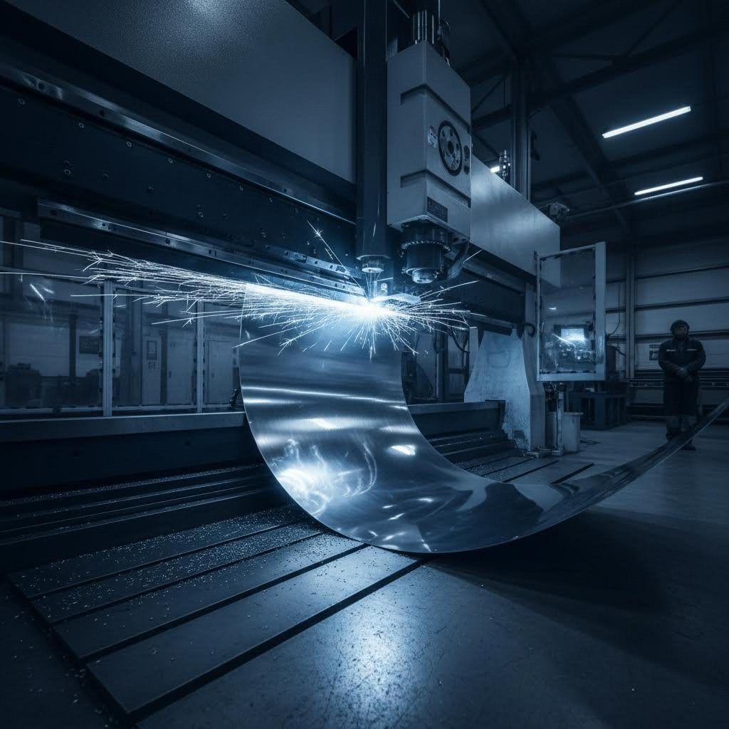
- Cutting: Laser cutting, shearing, or plasma methods remove material to create the basic shape with high precision.
- Bending and forming: Press brakes and forming equipment reshape the flat material into three-dimensional components without removing mass.
- Joining: Welding, riveting, or mechanical fastening connects individual parts into complete assemblies.
- Finishing: Surface treatments like powder coating or anodizing add durability and visual appeal.
Each step in this sequence demands careful attention to material properties and tolerances. When you define metalworking in the context of sheet materials, you're talking about a discipline where millimeters matter and precision directly impacts product quality.
Why Sheet Metalwork Matters in Modern Manufacturing
From construction to aerospace, automotive to medical equipment, this manufacturing discipline touches virtually every industry you can name. Why does it hold such importance across these diverse sectors?
The answer lies in three key advantages:
- Versatility: The material can be shaped into complex geometries while maintaining structural integrity, enabling designers to create nearly any form they envision.
- Durability: Properly fabricated components resist wear, corrosion, and environmental stress, delivering long service life in demanding applications.
- Cost-effectiveness: Compared to other manufacturing methods, this process offers excellent economies of scale, particularly for medium to high-volume production runs.
Consider the transportation sector alone. Emergency vehicles rely on fabricated metal for glove-box enclosures, side steps, and door-handle mounts. Commercial kitchens depend on stainless steel worktops and storage units. Retail environments feature custom display units and point-of-sale stands—all products of skilled sheet metal working.
Understanding the definition of sheet metal and its processing capabilities isn't just academic knowledge. It's the foundation for making informed decisions about material selection, design optimization, and manufacturing partnerships that directly impact your project's success.
Sheet Metal Materials and Gauge Selection Guide
Choosing the right material is half the battle in any fabrication project. Select poorly, and you'll face corrosion issues, forming difficulties, or budget overruns. Pick wisely, and your components will perform exactly as intended for years. Let's break down your options so you can make confident material decisions from day one.
Steel Varieties and Their Applications
Steel dominates the sheet metalwork landscape for good reason—it offers exceptional strength, weldability, and cost-effectiveness. But not all steel is created equal. Understanding the differences between carbon steel, stainless steel, and galvanized options helps you match material properties to application requirements.
Carbon steel serves as the workhorse of general fabrication. It's strong, affordable, and easy to work with, making it ideal for structural components, enclosures, and brackets where corrosion resistance isn't critical. However, untreated carbon steel will rust when exposed to moisture, so protective coatings or indoor applications are essential.
Stainless steel sheet brings chromium into the mix, creating a passive oxide layer that resists corrosion far better than carbon steel. The chromium combines with oxygen in the environment to form this protective barrier, making stainless steel the go-to choice for food processing equipment, medical instruments, and marine applications. Among stainless grades, 316 stainless steel stands out for its molybdenum content, which provides superior resistance to saltwater and chemical exposure—perfect for coastal installations or pharmaceutical environments.
Galvanized sheet metal offers a middle-ground solution. The hot-dip galvanizing process coats steel with a thin layer of zinc, creating a multi-layered barrier against corrosion at a fraction of stainless steel's cost. You'll find galvanized steel in HVAC ductwork, outdoor signage, automotive components, and construction applications where corrosion resistance matters but budgets are tight. Keep in mind that welding galvanized material requires proper ventilation, as zinc vaporizes at temperatures below steel's melting point.
Aluminum and Non-Ferrous Options
When weight matters more than raw strength, aluminum sheet metal becomes your best friend. This lightweight material weighs roughly one-third as much as steel while offering excellent corrosion resistance and formability. Aircraft fuselages, automotive body panels, and electronic enclosures frequently rely on aluminum for these very reasons.
What aluminum lacks in absolute strength, it compensates for with an impressive strength-to-weight ratio of 1/8 compared to stainless steel's 1/16. This means an aluminum structure supporting the same load as its steel counterpart will be larger but weigh approximately half as much—a critical advantage in aerospace and transportation applications.
Beyond aluminum, specialty materials serve niche requirements:
- Brass: An alloy of copper and zinc prized for its decorative appearance, antimicrobial properties, and low friction. Common in architectural hardware, musical instruments, and decorative panels.
- Bronze: Copper alloyed with tin rather than zinc, offering superior strength and marine corrosion resistance compared to brass. When weighing brass vs bronze, choose bronze for marine applications and brass for aesthetic appeal.
- Copper: Excellent electrical and thermal conductivity makes copper ideal for electrical components, heat exchangers, and roofing applications where its distinctive patina is desired.
- Titanium: Exceptional strength-to-weight ratio and corrosion resistance justify its premium cost in aerospace and medical implant applications.
Selecting the Right Gauge for Your Project
Here's where many newcomers stumble: gauge numbers work backwards from intuition. The higher the gauge number, the thinner the material. A 26-gauge sheet is paper-thin, while 7-gauge approaches plate territory. Understanding this relationship—and consulting a gauge size chart—prevents costly ordering mistakes.
The most commonly-used sheet metal sizes range from 26 gauge (thinner) to 7 gauge (thicker), with material transitioning to "plate" designation beyond 7 gauge (.188 inches). After that threshold, fabricators reference decimal equivalents rather than gauge numbers.
Practical gauge selection depends on your application:
- 11 gauge steel thickness (approximately 0.120 inches) handles structural applications, heavy-duty brackets, and equipment frames requiring significant load-bearing capacity.
- 14 gauge steel thickness (approximately 0.075 inches) suits general-purpose enclosures, moderate structural components, and automotive panels where strength and weight must balance.
- 18-20 gauge works well for light enclosures, HVAC components, and decorative elements where forming complex shapes takes priority over structural demands.
- 22-26 gauge serves electronics housings, precision brackets, and applications requiring intricate detail work.
One critical note: gauge thickness varies slightly between metal types. Ferrous and non-ferrous metals at the same gauge number have different actual thicknesses because gauge classification is based on weight rather than absolute dimension. Most fabrication shops measure aluminum, copper, and brass by decimal thickness rather than gauge to avoid confusion.
| Material Type | Typical Gauge Range | Key Properties | Best Applications |
|---|---|---|---|
| Carbon Steel | 7-26 gauge | High strength, weldable, affordable, requires coating for corrosion protection | Structural components, enclosures, brackets, indoor equipment |
| Stainless Steel (304/316) | 7-26 gauge | Corrosion resistant, durable, hygienic, higher cost | Food processing, medical equipment, marine hardware, architectural features |
| Galvanized Steel | 10-26 gauge | Zinc-coated corrosion protection, cost-effective, weld fume concerns | HVAC ductwork, outdoor signage, automotive parts, construction |
| Aluminum | .020"-.250" (decimal) | Lightweight, corrosion resistant, excellent formability, good conductivity | Aerospace, automotive panels, electronics enclosures, heat sinks |
| Brass | .020"-.125" (decimal) | Decorative finish, antimicrobial, low friction, easy to machine | Architectural hardware, decorative panels, musical instruments |
| Copper | .020"-.125" (decimal) | Superior electrical/thermal conductivity, naturally antimicrobial | Electrical components, heat exchangers, roofing, bus bars |
Material selection isn't just about checking boxes on a specification sheet. Consider the full lifecycle: How will the component be formed? What environment will it face? What finishing options complement your chosen material? Armed with this knowledge, you're ready to explore the fabrication processes that transform raw sheets into finished components.
Essential Sheet Metal Fabrication Processes Explained
You've selected your material and gauge—now what? The magic happens in the fabrication stage, where flat metal sheet transforms into functional three-dimensional components. Understanding each sheet metal process helps you choose the right method for your project, avoid costly mistakes, and communicate effectively with manufacturing partners.
Let's walk through the three core operations that define sheet metal fabrication: cutting, bending, and joining.
Cutting Methods Compared
Every fabrication project starts with cutting raw material to size. But which method should you choose? The answer depends on your material type, thickness, precision requirements, and budget. Here's how the three dominant cutting technologies stack up.
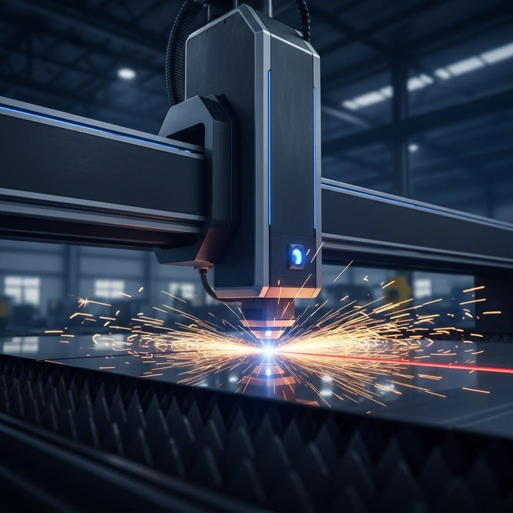
Laser Cutting
Laser cutting uses a concentrated beam of light to melt and vaporize material along a programmed path. Modern CNC laser cutters achieve tolerances as tight as ±0.003 mm, making them the precision champion for intricate work.
When should you choose laser cutting?
- Complex geometries with tight radii, sharp corners, or micro-profiles
- Thin to medium thickness materials (up to approximately 25mm)
- Applications requiring clean, burr-free edges with minimal post-processing
- Non-metallic materials like acrylic, rubber, or wood (depending on laser type)
- High-precision components where surface finish matters
One critical consideration: kerf width. The laser beam removes a small amount of material as it cuts—typically 0.1 to 0.3mm depending on power settings and material. Factor this into your design dimensions to ensure accurate final part sizes.
Plasma Cutting
Plasma cutting harnesses ionized gas heated to over 20,000°C to slice through conductive metals. While less precise than laser, plasma excels at cutting thick materials quickly and affordably.
When does plasma cutting make sense?
- Thicker materials—plasma handles up to 50mm comfortably, with some machines reaching 100mm or more
- Heavy industrial applications like structural beams, boat parts, and agricultural machinery
- Projects where speed and cost matter more than ultra-fine precision
- Conductive metals only (steel, stainless steel, aluminum)
Expect tolerances around ±0.1mm with plasma cutting—perfectly acceptable for structural work but potentially problematic for precision assemblies. Plasma also produces rougher edges and slag that require grinding or finishing.
Shearing
Shearing uses opposing blades to make straight cuts through metal sheet—think of industrial-scale scissors. It's the fastest method for simple straight-line cuts on thin to medium gauge materials.
Consider shearing when you need:
- High-volume blanking operations with straight edges
- Quick material sizing before secondary operations
- Cost-effective processing of lighter gauge materials
The limitation? Shearing can't produce curves, holes, or complex profiles. It's a roughing operation, not a precision finishing process.
Bending and Forming Fundamentals
Cutting creates profiles. Bending creates structure. When you bend a metal sheet, you're inducing controlled plastic deformation—permanently reshaping the material without removing mass. This is where flat blanks become enclosures, brackets, and structural components.
Press Brake Operations
The press brake is the workhorse of sheet metal bending. A movable punch forces material into a stationary die, creating precise angular bends. Modern CNC press brakes can execute complex multi-bend sequences with remarkable repeatability.
Understanding the physics helps you predict results. When metal bends, the inner surface experiences compressive stress while the outer surface experiences tensile stress. Only a thin internal layer—the neutral axis—remains unstretched. As bend angles increase, this neutral axis shifts inward toward the bend radius, affecting your flat pattern calculations.
Then there's springback—the tendency of bent metal to partially return toward its original shape when forming pressure releases. Springback increases proportionally with material yield strength and becomes more pronounced in large-radius bends where plastic deformation is limited. Experienced fabricators compensate by overbending slightly, letting springback bring the part to final dimension.
Roll Forming
For continuous profiles like channels, angles, and custom cross-sections, roll forming passes material through a series of roller dies that progressively shape it. This process excels at high-volume production of consistent linear profiles.
How Bending Affects Material Properties
Every bend changes your material. The outer surface stretches and thins slightly while the inner surface compresses. Grain structure realigns. Hardness increases in the bend zone through work hardening. These changes aren't defects—they're predictable physics you can leverage or compensate for depending on your application.
Joining Techniques
Individual formed parts rarely stand alone. Joining operations connect components into complete assemblies. Your joining method affects structural integrity, appearance, and production efficiency.
MIG vs TIG Welding: Choosing Your Approach
When comparing tig vs mig welding for sheet metal applications, the decision comes down to speed versus precision.
MIG welding (Gas Metal Arc Welding) feeds a continuous wire electrode through a welding gun while shielding gas protects the weld pool. It's faster, easier to learn, and excellent for production environments.
Choose MIG welding when:
- Production speed matters more than cosmetic perfection
- Welding thicker materials where heat input is less critical
- Training less experienced operators
- Working on steel, stainless steel, or aluminum in general fabrication
TIG welding (Gas Tungsten Arc Welding) uses a non-consumable tungsten electrode with a separate filler rod, offering superior control and aesthetic results.
Choose TIG welding when:
- Precision and weld appearance are critical
- Working with thin materials where burn-through risks are high
- Joining exotic metals like titanium or magnesium
- Creating visible welds on decorative or architectural components
The trade-off? TIG welding is slower and requires more operator skill, which translates to higher labor costs per weld.
Rivets and Mechanical Fastening
Not every joint needs welding. Rivets create permanent mechanical connections without heat, preserving material properties in the joint zone. They're ideal for joining dissimilar metals, attaching thin sheets to thicker structures, and applications where weld distortion is unacceptable.
Mechanical fasteners like screws, bolts, and clinch joints offer another alternative—particularly valuable when disassembly might be required for service or replacement.
Understanding these sheet metal processes gives you the vocabulary to discuss projects intelligently with fabrication partners. But even perfect process selection can't prevent defects if you don't know what to watch for—which brings us to troubleshooting the problems that plague even experienced fabricators.
Tools and Equipment for Sheet Metal Operations
You've mastered material selection and fabrication processes—but without the right tools, even the best plans fall flat. Whether you're building your first toolkit or evaluating a major equipment investment, understanding which tools match which tasks separates frustrating guesswork from efficient production.
Here's the reality: the right metal cutter makes clean work of what would otherwise be a mangled mess. The correct drill bit turns a precise hole into a perfect fit. Let's break down exactly what you need—and when you need it.
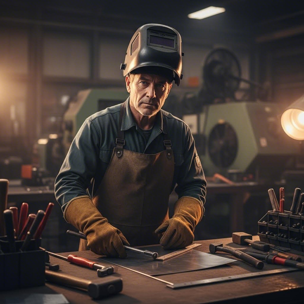
Hand Tools Every Sheet Metal Worker Needs
Before reaching for power equipment, skilled fabricators rely on manual tools for layout, cutting, and forming operations. These essentials form the foundation of any sheet metal toolkit:
Layout and Measuring Tools
- Combination square: Look for stainless steel or top-quality aluminum construction. According to industry experts, the average fabricator gets heavy use out of this tool—spend the extra cash to get a good one that holds accurate angles over years of daily use.
- Scribe and marking tools: Precision layout starts with clean, visible marks that won't rub off during handling.
- Measuring tapes and rulers: Both metric and imperial calibrations help you work across international specifications.
Cutting Tools
- Aviation snips: These compound-leverage shears come in left-cut, right-cut, and straight varieties. Color-coded handles (red, green, yellow) indicate cutting direction.
- Throatless shear: This mounted tool offers leverage to cut stainless steel or aluminum efficiently, handling curved, irregular, or straight cuts with ease. The tall handle design provides mechanical advantage that hand snips simply can't match.
- Wire cutters: Essential for snipping frayed ends and general-purpose cutting across many projects.
Forming and Fastening Tools
- Hand seamers: These flat-jawed pliers bend and flatten edges, creating seams and hems without specialized equipment.
- Sheet metal clamps: Acting as heavy-duty clothespins, these fasteners hold multiple sheets together before permanent joining—critical for maintaining alignment during welding or riveting.
- Rivet guns: Manual pop rivet tools create permanent mechanical connections without heat or electricity.
Safety Equipment
No toolkit is complete without protection. A quality welding helmet—expect to invest $200-$400 for a dependable one—protects your eyes and face during joining operations. Cutting glasses reduce accident risk during layout and fabrication work. As experienced fabricators emphasize: the safety of your eyes and face is worth the investment.
Power Tools and Machine Selection
When production volume increases or material thickness challenges hand tools, power equipment takes over. Understanding your options helps you invest wisely.
Angle Grinders
This versatile power tool polishes, cuts, and grinds metal by hand. Build a solid disc collection including cutoff wheels, grinding wheels, wire wheels, and flap discs for finishing work. Include both super abrasives and conventional abrasives—you'll get extensive use from this tool, so invest in one strong enough to last.
Drill Presses and Portable Drills
Hole-making demands precision. Any capable shop needs a drill, a drill press, or both. Start with a standard length drill bit set and machine screw drill bits, then expand as projects require. Consulting a drill size chart ensures your holes match hardware specifications exactly.
Why does hole sizing matter so much? The difference between a close fit and a free fit determines assembly quality. For example, a 1/4-20 threaded fastener has a 0.250" major diameter—but your clearance hole should measure 0.257" to 0.266" depending on fit requirements. A comprehensive drill bit size chart becomes your reference for matching hole sizes to fastener specifications across both imperial and metric standards.
CNC Press Brakes
For precision bending at production volumes, CNC press brakes deliver repeatable results that manual equipment can't match. When evaluating these machines, tooling selection becomes critical. As automation specialists note, your tooling choice is where the magic meets the metal—a well-matched setup sharpens part quality, slashes waste, and locks in consistency bend after bend.
Key considerations for press brake tooling include:
- Die opening should match punch tip radius and material thickness to avoid distortion
- V-die openings typically measure 8-10 times the material thickness for optimal results
- Precision-ground tools deliver consistent performance across production runs
- Tooling must be compatible with your specific machine type—CNC versus hydraulic systems have different requirements
Laser Cutters and Die Cut Machines
High-volume cutting operations demand dedicated equipment. A laser cutter handles complex profiles with exceptional precision, while a die cut machine excels at repetitive blanking operations where speed trumps flexibility. Your production volume and part variety determine which technology makes economic sense.
Support Equipment
Don't overlook support infrastructure. A sturdy welding cart keeps equipment mobile and organized. Material handling equipment—from simple sheet lifters to overhead cranes—prevents injuries and speeds workflow.
Matching Tools to Project Requirements
Sounds complex? It doesn't have to be. Use this decision framework to match tools to your specific situation:
Consider Material Type
Aluminum cuts and forms easily with lighter-duty tools. Stainless steel demands more robust equipment and sharper tooling. Hardened materials may require specialized carbide or diamond-coated tooling.
Factor in Thickness
Hand snips handle gauges up to approximately 18 gauge in steel. Heavier materials need throatless shears, power shears, or plasma/laser cutting. Your drill chart selection also varies with thickness—thicker materials require stepped drilling approaches and slower speeds to prevent work hardening.
Evaluate Production Volume
One-off prototypes justify hand tools and manual equipment. Recurring production runs warrant CNC investment. The break-even point depends on your labor costs, tolerance requirements, and delivery timelines.
| Tool Type | Best For | Material Limitations | Skill Level Required |
|---|---|---|---|
| Aviation Snips | Thin gauge cutting, curved profiles, quick trimming | Up to 18 gauge steel; struggles with stainless | Beginner |
| Throatless Shear | Medium gauge straight and curved cuts | Up to 14 gauge steel and aluminum | Beginner to Intermediate |
| Angle Grinder | Cutting, grinding, deburring, finishing | All common sheet metals with appropriate discs | Intermediate |
| Drill Press | Precision holes, consistent depth, perpendicular drilling | All materials with proper bit selection and speeds | Beginner to Intermediate |
| CNC Press Brake | Production bending, complex multi-bend parts, tight tolerances | Capacity varies by machine tonnage and length | Advanced (programming) / Intermediate (operation) |
| Laser Cutter | Complex profiles, precision cuts, minimal post-processing | Up to ~25mm depending on power; reflective materials challenging | Advanced |
| Manual Hand Seamer | Edge bending, seam closing, small forming operations | Thin gauges only; limited by hand strength | Beginner |
When you're just starting out, help yourself by storing tools in a strong backpack for portability between job sites. Once you're established in a stable shop, keeping tools organized on-site improves efficiency and reduces loss.
With the right tools in hand, you're equipped to execute clean cuts, precise bends, and solid joints. But what happens when results don't match expectations? Even experienced fabricators encounter defects—and knowing how to identify and solve them separates professionals from frustrated amateurs.
Troubleshooting Common Sheet Metal Defects
Even with perfect material selection and proper tooling, defects happen. The difference between a frustrated fabricator and a confident professional? Knowing exactly why problems occur—and how to fix them before scrapping expensive parts. Let's tackle the three most common issues that plague every sheet metal process: springback, forming defects, and edge quality problems.
Understanding and Preventing Springback
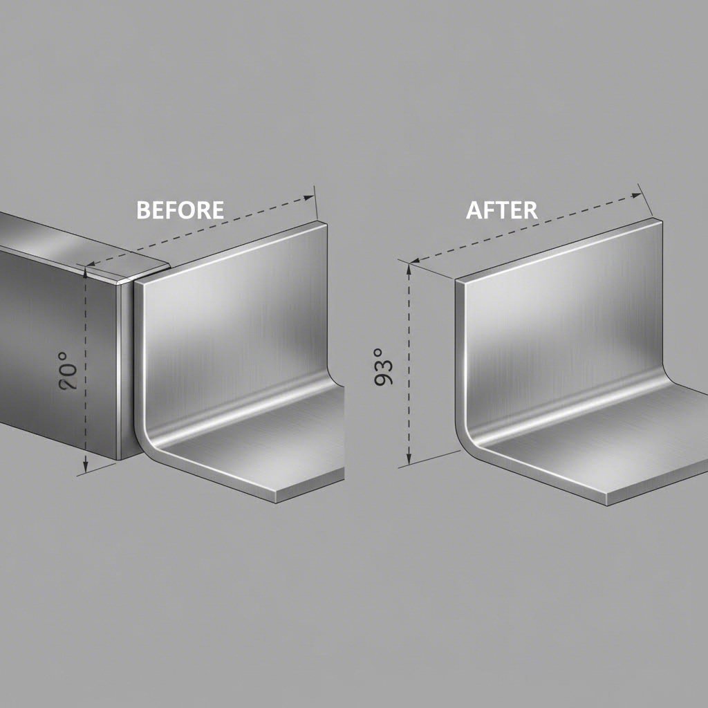
You bend a piece of sheet metal to 90 degrees, release the pressure, and watch it spring back to 88 degrees. Sound familiar? This frustrating phenomenon affects every bending operation, but understanding the physics helps you compensate effectively.
Why does springback occur? Two forces are at work. First, when metal bends, the inner region compresses while the outer region stretches, creating uneven molecular density. The compressive forces on the inside are weaker than the tensile forces on the outside, causing the material to try returning to its flat position. Second, stress-strain properties mean the metal enters an elastic zone before permanent deformation begins—and that elastic component wants to recover.
Symptoms of springback:
- Bend angles consistently measuring less than programmed values
- Parts requiring multiple correction bends to achieve specifications
- Inconsistent angles between parts in the same batch
- Dramatic angle deviation in large-radius bends
Causes and contributing factors:
- High-strength materials—the stronger the tensile strength, the greater the springback
- Large bend radii relative to material thickness (springback increases dramatically when radius exceeds 8x thickness)
- Wider die openings in air forming operations
- Inconsistent material properties within the same batch
Compensation strategies:
- Overbending: Program your press brake to bend past the target angle, allowing springback to bring the part to final dimension. For common materials with a 1:1 ratio of radius to thickness, expect 0.5-2 degrees of springback—mild steel at the low end, stainless steel and aluminum requiring more compensation.
- Bottom bending: Forcing the material to contact the die bottom creates springforward that counteracts springback, producing more consistent angles.
- Tooling selection: Dies with openings over 0.500" typically feature 88-degree angles rather than 90 degrees to compensate for increased springback from larger radii.
- Real-time angle compensation: Modern CNC press brakes use sensors or lasers to measure springback at the workpiece and adjust each bend automatically.
Material type dramatically affects your compensation needs. Cold-rolled steel with a 1:1 radius-to-thickness ratio produces roughly 0.5 degrees of springback. The same geometry in 304 stainless steel? Expect closer to 1.75 degrees. High-strength steels push even higher.
Solving Wrinkling and Cracking Issues
Wrinkling and cracking represent opposite ends of the forming metal sheet spectrum—one from too much material compression, the other from excessive stretching. Both ruin parts and waste resources if you don't address root causes.
Wrinkling
When metal sheet processing involves deep draws or complex curves, excess material bunches up and creates irregular surface deformation. This defect appears most often in thin sheets and curved areas where compressive stress concentrates.
Symptoms of wrinkling:
- Wavy, corrugated surface texture in formed areas
- Irregular bumps or ridges on curved sections
- Parts that won't nest or assemble properly due to dimensional distortion
Causes of wrinkling:
- Insufficient blank holder pressure during drawing operations
- Uneven strain distribution concentrating excess material in localized zones
- Material too thin for the forming depth required
- Improper die design creating unbalanced stress patterns
Prevention strategies:
- Increase blank holder force to maintain tension and prevent material bunching
- Optimize die geometry to distribute strain more evenly
- Consider thicker gauge material for deep-draw applications
- Add draw beads to control material flow into the die cavity
Cracking
Cracks form when sheet metal stretching exceeds the material's ductility limits. This failure typically occurs at stress concentration points—sharp corners, tight radii, or areas where the material thins excessively during forming.
Symptoms of cracking:
- Visible splits or fractures at bend lines or draw edges
- Thinning and necking before complete fracture
- Surface strains appearing as rough texture before failure
Causes of cracking:
- Bend radius too tight for material thickness and ductility
- Material with too many impurities, pores, or internal defects
- Excessive stamping pressure or speed creating strain rates beyond material limits
- Insufficient lubrication increasing friction and localized stress
- Bending across the grain direction rather than with it
Prevention strategies:
- Specify minimum bend radii appropriate for your material—typically 1x material thickness for mild steel, 2x or more for harder alloys
- Select materials with adequate ductility for your forming requirements
- Apply proper lubrication to reduce friction during the sheet metal production process
- Consider preheating or annealing brittle materials before forming
- Orient blanks so bends run with the grain direction when possible
Addressing Burrs and Edge Quality Problems
Every cutting operation leaves behind imperfections. Burrs—those tiny sharp ridges clinging to cut edges—create safety hazards, interfere with assembly, and compromise appearance. Understanding why they form helps you minimize them during cutting and remove them efficiently afterward.
Symptoms of burr problems:
- Sharp, raised edges that catch on adjacent parts or handling equipment
- Poor fit during assembly requiring excessive force
- Injury risk to operators handling parts
- Coating adhesion failures at rough edges
Causes of excessive burring:
- Dull or worn cutting tools that tear rather than shear material
- Improper clearance between punch and die in stamping operations
- Cutting parameters (speed, feed, power) mismatched to material
- Material with low ductility more prone to edge tearing
Deburring solutions:
The right deburring approach depends on your production volume, part geometry, and quality requirements:
- Manual deburring: Files, scrapers, and sandpaper offer fine control for small batches or hard-to-reach areas. Labor-intensive but precise.
- Mechanical deburring: Abrasive belts, rotary tools, and grinding wheels remove burrs quickly on accessible edges. Ideal for production environments.
- Vibratory finishing: Parts tumble with abrasive media, processing multiple components simultaneously. Excellent for high-volume small parts.
- Thermal deburring: Controlled combustion removes burrs from complex geometries without damaging machined surfaces—effective for intricate sheet metal forms.
- Electrochemical deburring: Electrical current selectively removes burr material while leaving surrounding areas untouched. Ideal for precision components in aerospace and electronics.
Prevention during cutting:
- Maintain sharp tooling and replace worn punches before quality degrades
- Optimize punch-to-die clearance—typically 5-10% of material thickness per side
- Adjust cutting speed and feed rates to match material characteristics
- Consider laser cutting for applications where edge quality is critical—the kerf produces minimal burring compared to mechanical methods
Defect prevention isn't just about fixing problems after they appear. It's about understanding how material properties, tooling condition, and process parameters interact throughout metal sheet processing. When you control these variables proactively, troubleshooting becomes the exception rather than the rule—freeing you to focus on the design principles that prevent problems before fabrication even begins.
Safety Practices and Hazard Prevention
Here's something most fabrication guides overlook entirely: working with sheet metal can seriously injure you. Sharp edges slice through skin in an instant. Heavy sheets crush fingers. Cutting and welding operations generate hazards that cause permanent damage if you're not prepared. Yet safety rarely gets the attention it deserves in technical discussions.
Let's fix that. Whether you're setting up your first sheet metal workshop or managing an established production floor, these practices protect you and your team from preventable injuries.
Personal Protective Equipment Requirements
The right PPE creates a barrier between you and the hazards inherent in every fabrication operation. According to the National Safety Council, injuries to hands and fingers account for approximately 25 percent of all work injuries—many caused by inadequate protective equipment. Here's what you need for different operations:
Hand Protection
- Cut-resistant gloves: Essential when handling raw sheet metal material. Look for ANSI cut level A4 or higher for heavy gauge work.
- Welding gloves: Thick leather gauntlets protect against sparks, spatter, and radiant heat during joining operations.
- General work gloves: Lighter-duty options for assembly and finishing work where dexterity matters more than cut protection.
Eye and Face Protection
- Safety glasses: Minimum protection for all shop activities. Side shields are non-negotiable when cutting or grinding.
- Face shields: Add over safety glasses when machining sheet metal, grinding, or performing operations that generate significant debris.
- Welding helmets: Auto-darkening models with appropriate shade ratings (typically 10-13 for arc welding) protect against intense UV and infrared radiation.
Hearing Protection
Cutting, bending, and forming machines generate noise levels that cause permanent hearing damage over time. The high noise levels from cutting and bending equipment require consistent hearing protection. Foam earplugs work for intermittent exposure; earmuff-style protection suits continuous operations or particularly loud equipment.
Additional PPE
- Steel-toed boots: Protect feet from dropped sheets and heavy tooling.
- Long sleeves and aprons: Leather or flame-resistant materials shield against sparks and hot metal during welding.
- Respiratory protection: Required when welding galvanized materials, aluminum welding, or working in areas with inadequate ventilation.
Safe Handling Practices for Sheet Metal
Sheet metal material presents unique handling challenges. Edges are sharp enough to cut through standard work gloves. Large sheets are awkward and heavy. Improper technique leads to back injuries, lacerations, and crushed extremities.
Proper Lifting Techniques
Before lifting any sheet, examine the object for sharp corners, slippery spots, or other potential hazards. Then follow these steps:
- Stand close to the load with feet shoulder-width apart, one foot slightly forward for balance.
- Squat by bending at the knees—never at the waist.
- Get a firm grasp before beginning the lift, using gloves to protect against sharp edges.
- Lift with your legs by straightening them, keeping the load close to your body.
- Turn using your feet, not your torso, when changing direction.
When should you ask for help? Anytime the load is too bulky to grasp properly, when you cannot see around it, or when a secure grip cannot be maintained.
Material Storage Best Practices
- Store sheets vertically in racks designed for the purpose—horizontal stacking creates crushing hazards and complicates retrieval.
- Apply edge protectors to exposed sheet edges in storage areas.
- Keep storage areas organized with clear pathways for material handling equipment.
- Limit quantities of stored materials to what's needed for near-term production.
- Never store materials within 18 inches of sprinkler heads or block emergency equipment access.
Hazard Awareness by Process Type
Different operations create different risks. Understanding what you're facing helps you prepare appropriately for working with metal sheets in any context.
Cutting Operation Hazards
- Flying debris from shearing, laser cutting, and plasma operations
- Severe lacerations from contact with cut edges or material fragments
- Eye injuries from metal particles and bright arcs
- Burns from hot metal and sparks during plasma cutting
Safety checklist: Safety glasses with side shields, cut-resistant gloves, hearing protection, face shield for plasma operations, proper machine guarding in place.
Welding and Joining Hazards
- Burns from hot metal surfaces, sparks, and radiant heat
- Eye damage from UV and infrared radiation
- Toxic fume inhalation—especially when welding galvanized or coated materials
- Electrical shock from improperly grounded equipment
Safety checklist: Auto-darkening welding helmet, leather welding gloves and jacket, adequate ventilation or respiratory protection, fire extinguisher within reach, grounding verified before starting.
Forming and Bending Hazards
- Crushing injuries from press brakes and forming equipment
- Pinch points between material and tooling
- Material whip when springback releases stored energy
- Repetitive motion injuries from manual forming operations
Safety checklist: Machine guards in place and functional, two-hand controls or light curtains active, keep hands clear of pinch points, use ergonomic techniques for repetitive tasks.
Maintaining a Safe Workshop Environment
A clean, organized sheet metal workshop prevents accidents before they happen. Remove metal scraps, tools, and debris regularly to minimize slips, trips, and falls. Keep exit paths clear at all times. Establish and practice emergency procedures for fires or equipment failures so everyone responds quickly and effectively when seconds count.
Safety isn't a one-time training topic—it's a daily practice that becomes second nature with consistent attention. With proper PPE, smart handling techniques, and hazard awareness built into your workflow, you can focus on what matters: producing quality parts efficiently. And speaking of quality, even the safest fabrication practices can't rescue a poorly designed part—which brings us to the design principles that prevent costly mistakes before they reach the shop floor.
Design Mistakes to Avoid in Sheet Metal Projects
You've mastered safety practices and defect troubleshooting—but what if those problems never occurred in the first place? Most fabrication headaches trace back to design decisions made long before metal hits the press brake. A small sheet metal part with poorly placed holes or impossible bend radii costs far more to fix than to design correctly from the start.
Here's the uncomfortable truth: design changes become exponentially more expensive as projects progress. Catching a tolerance issue during CAD review costs minutes. Discovering it after tooling is built? That's scrapped parts, delayed schedules, and frustrated customers. Let's examine the design principles that prevent these costly surprises.
Tolerance and Fit Considerations
Specifying tolerances is where many designers stumble. Too tight, and you drive costs through the roof. Too loose, and parts won't fit together properly. Understanding what standard sheet metal fabrication processes can actually achieve helps you specify appropriately.
Standard sheet metal processes typically achieve ±0.010" to ±0.030" economically. Specifying tolerances tighter than ±0.005" dramatically increases costs because parts require secondary machining operations or more expensive production methods. Before demanding ultra-precise dimensions, ask yourself: does this feature actually need that level of accuracy?
For bend angles, expect a ±1 degree tolerance as standard. If your design requires tighter angular control, communicate this early—it affects tooling selection and may require additional verification steps during production.
Design rule: Avoid unnecessarily tight tolerances. Standard sheet metal processes achieve ±0.010" to ±0.030" economically—anything below ±0.005" drives up costs dramatically.
When designing mating parts, account for cumulative tolerance stack-up. If three features each have ±0.015" tolerance, the worst-case variation between them could reach ±0.045". Design clearances and fits with this reality in mind.
Design for Manufacturability Principles
Design for manufacturability (DFM) means creating parts that are not just functional but also practical to produce. These principles apply to every piece of sheet metal you design, regardless of complexity.
Bend Radius Requirements
At minimum, the smallest bend radius should be at least equal to the sheet thickness to avoid fractures or distortions. Tighter radii stress the material beyond its limits, causing cracks on the outer surface. For harder materials like stainless steel or high-strength alloys, specify even larger radii—typically 1.5x to 2x material thickness.
Keeping the bend radius consistent across all bends makes parts more cost-effective. Mixed radii require tooling changes during production, adding time and expense. Standard options like 0.030", 0.060", 0.090", and 0.120" are readily available with shorter lead times.
Hole Placement Near Bends
This mistake appears constantly: designers place holes too close to bend lines, then wonder why they deform during forming. When metal bends, it stretches on the outer surface, pulling nearby features out of position.
For circular holes, maintain a distance of at least 2.5 times the material thickness plus the bend radius from any bend line. For slots, increase this to 4 times material thickness plus the bend radius. Ignore these minimums, and you'll see distorted holes that won't accept fasteners properly.
Similarly, holes positioned too close to part edges create a "bulging" effect. Leave at least 2 times the sheet thickness between hole edges and part edges.
Minimum Flange Dimensions
Flanges that are too short can't be gripped properly by forming equipment. The minimum flange length must be at least 4 times the material thickness. Shorter flanges either won't form correctly or require specialized tooling that increases costs.
Bend Relief Requirements
Without proper relief cuts, material tears at bends and corners deform. Always provide relief proportional to material thickness—typically 1 to 1.5 times the thickness. The length of relief cuts should exceed the bend radius to prevent stress concentration at bend lines.
Avoiding Costly Redesigns
Getting designs right the first time requires thinking like a fabricator, not just an engineer. Here's how experienced designers prevent expensive rework:
Choose Standard Materials and Gauges
Standard gauges cost less and have better availability than custom thicknesses. Before specifying an unusual gauge, verify it offers meaningful performance benefits that justify the premium.
Account for Sheet Metal Properties
Different materials behave differently. Aluminum requires larger bend radii than steel due to its lower ductility. Stainless steel springs back more than mild steel, affecting final dimensions. Understanding these sheet metal properties before finalizing your design prevents unpleasant surprises during fabrication.
Simplify Sheet Metal Shapes
Complex geometries drive up manufacturing time and cost. Each additional bend, cutout, or feature adds operations. Before adding complexity, ask whether simpler sheet metal shapes could achieve the same function. Combining features into single parts when possible reduces assembly time and potential failure points.
Get Manufacturing Input Early
Working with experienced fabricators during the design phase—not after drawings are finalized—catches issues before they become expensive problems. Prevention costs far less than correction. Most quality fabrication partners offer DFM review services that identify manufacturability concerns while changes are still easy to implement.
Design rule: Place holes at least 2.5 times material thickness plus bend radius away from bend lines. For slots, increase to 4 times material thickness plus bend radius.
Create a Manufacturing Review Checklist
Build a checklist specific to your common projects that includes items like minimum bend radius, hole-to-edge distances, and standard fastener specifications. Review every design against this checklist before releasing drawings for fabrication.
Design decisions made today determine manufacturing success tomorrow. By specifying appropriate tolerances, following DFM principles, and engaging fabrication partners early, you prevent the defects, delays, and cost overruns that plague poorly planned projects. With your design fundamentals solid, you're ready to consider the finishing options that transform fabricated parts into polished final products.
Surface Finishing Options for Sheet Metal Parts
Your fabricated components are formed, joined, and deburred—but they're not finished. Without proper surface treatment, even the most precisely manufactured parts fall short of their potential. Bare metal corrodes. Uncoated surfaces scratch. Raw finishes fail to meet customer expectations. The right finishing process transforms functional parts into durable, attractive products ready for their intended environment.
Surface finishing isn't just cosmetic. According to industry specifications, finishes serve multiple functional objectives including corrosion resistance, wear protection, electrical properties, and compliance with industry standards like ASTM, MIL, and ISO. Understanding your options helps you specify the right treatment for your application—before parts leave the fabrication floor.
Powder Coating and Paint Systems
When durability and appearance matter equally, powder coat finishes deliver exceptional results. Unlike traditional liquid paints, this process uses dry powders that are electrostatically charged and cured with heat, creating a tough finish that resists corrosion, chipping, and fading far better than conventional coatings.
How does it work? The process involves three key stages:
- Surface preparation: Parts are cleaned to remove dirt, grease, and contaminants. This step is critical—poor adhesion ruins even the best coating application.
- Powder application: Electrically charged powder particles are sprayed onto grounded metal surfaces using electrostatic spray deposition (ESD). The charge ensures even coverage and strong initial adhesion.
- Curing: Coated parts enter ovens at 325–450°F (163–232°C) for 10–30 minutes, depending on coating thickness. The powder melts and flows into a smooth, durable film.
Why choose powder coating over liquid paint? The advantages are compelling:
- Superior durability: Powder-coated surfaces meet strict performance standards including pencil hardness (ASTM D3363) and salt spray resistance (ASTM B117).
- Environmental benefits: No solvents mean no volatile organic compounds (VOCs). Transfer efficiency approaches 98% thanks to reclaimable overspray.
- Design flexibility: Custom finishes match Pantone and RAL color standards, including metallic, textured, and transparent options.
- Excellent edge coverage: Unlike liquid coatings that thin at edges, powder builds up evenly on corners and complex geometries.
Typical coating thickness ranges from 50–150 microns, providing substantial protection without dimensional concerns for most applications. You'll find powder coating on everything from automotive components and industrial enclosures to architectural assemblies and corrugated metal panels used in construction.
The main limitation? Substrate materials must withstand curing temperatures. Some plastics and heat-sensitive components require alternative finishing methods like UV-cured powder coatings or liquid paint systems.
Anodizing for Aluminum Components
Aluminum sheet metal already resists corrosion naturally, but anodizing takes protection to another level. This electrochemical conversion process transforms the aluminum surface into a controlled oxide layer that's integral to the base metal—it can't peel or flake because it's not a separate coating.
When should you specify anodized aluminum? Consider this finish when your application requires:
- Enhanced corrosion and wear resistance beyond raw aluminum's natural properties
- Improved electrical insulation for electronic housings
- Decorative color options achieved through dye absorption
- Compliance with aerospace or military specifications (MIL-A-8625)
Three main anodizing types serve different requirements:
Type I (Chromic Acid Anodizing) produces the thinnest oxide layer and offers excellent corrosion protection when properly sealed. It's suitable for welded assemblies but carries higher costs and environmental concerns due to chromium use.
Type II (Sulfuric Acid Anodizing) is the most common method, producing oxide layers of 5–25 microns. Its porous surface absorbs a wide range of dyes, enabling custom colors for aesthetic applications. Type II works across many aluminum alloys and suits aerospace, medical, electronic, and defense applications.
Type III (Hardcoat Anodizing) creates the thickest, hardest finish at 25–100 microns. When components face extreme conditions of abrasion, corrosion, and everyday wear, hardcoat anodizing delivers. You'll find it on valve components, pistons, sliding parts, hinges, and gears in automotive, aerospace, and industrial applications.
One important note: anodizing only works on aluminum and its alloys. Steel, stainless steel, and other metals require different finishing approaches.
Plating and Protective Coatings
When aluminum anodizing isn't an option—or when you need specific surface properties—metal plating deposits thin metallic layers onto your substrate through electrolytic or electroless processes.
Zinc Plating provides sacrificial corrosion protection at an economical price point. The zinc layer corrodes preferentially, protecting the underlying steel even if the coating is scratched. This makes zinc plating ideal for fasteners, brackets, and hardware exposed to moisture. Hot-dip galvanizing—coating steel in molten zinc—creates thicker layers (45–85 microns) for structural steel, outdoor infrastructure, and agricultural equipment.
Nickel Plating combines wear resistance with corrosion protection. It's commonly used as an undercoat beneath chrome or as a standalone finish for components requiring both durability and moderate corrosion resistance.
Chrome Plating delivers exceptional hardness and aesthetic appeal. Decorative chrome creates the brilliant mirror finish seen on automotive trim, while hard chrome provides wear resistance for industrial tooling and hydraulic components.
Key considerations when specifying plating:
- Typical thicknesses range from 2–25 microns—account for this in dimensional planning
- High-strength steels risk hydrogen embrittlement during electrolytic plating; post-plate baking may be required
- Tight process control ensures uniform thickness across complex geometries
- Plating improves surface conductivity and solderability for electrical components
| Finish Type | Compatible Materials | Durability | Typical Applications |
|---|---|---|---|
| Powder Coating | Steel, stainless steel, aluminum | Excellent impact, chip, and UV resistance; 50–150 micron thickness | Industrial enclosures, automotive components, architectural assemblies |
| Type II Anodizing | Aluminum alloys only | Good corrosion and wear resistance; 5–25 micron oxide layer; dyeable | Electronics housings, aerospace components, architectural aluminum |
| Type III Hardcoat Anodizing | Aluminum alloys only | Exceptional hardness and abrasion resistance; 25–100 micron oxide layer | Valve components, pistons, gears, sliding parts |
| Zinc Plating | Steel, iron | Sacrificial corrosion protection; 2–25 micron thickness | Fasteners, brackets, electrical components, automotive hardware |
| Hot-Dip Galvanizing | Steel | Long-term outdoor corrosion resistance; 45–85 micron coating | Structural steel, outdoor infrastructure, agricultural equipment |
| Chrome Plating | Steel, aluminum, copper alloys | High surface hardness; excellent aesthetic finish | Automotive trim, hydraulic components, decorative hardware |
| Nickel Plating | Steel, copper, aluminum | Good wear and corrosion resistance; often used as undercoat | Electronics, industrial machinery, undercoat for chrome |
Selecting the right finish requires balancing multiple factors: base material compatibility, operating environment, mechanical requirements, regulatory compliance, and budget. Early collaboration with your fabrication partner—ideally during the design phase—ensures your finish selection complements both the manufacturing process and end-use requirements.
With materials selected, fabrication complete, and finishes specified, you're ready to consider the final step: partnering with the right manufacturing experts to bring your designs to production reality.
Partnering with Sheet Metal Fabrication Experts
You've designed your parts, selected materials, and specified finishes—but success ultimately depends on your manufacturing partner. Whether you're searching for "sheet metal near me" or evaluating steel fabricators across the country, choosing the right metal fab shop determines whether your project ships on time with the quality you expect.
The difference between a smooth production run and a nightmare of delays, rework, and cost overruns often comes down to preparation and partner selection. Let's walk through how to set your project up for success from the first quote request through volume production.
Preparing Your Design Files
Before contacting any metal fabrication shop, get your documentation in order. Incomplete or unclear files create confusion, delay quotes, and introduce errors that cascade through production. Here's what fabricators need to provide accurate pricing and manufacture your parts correctly.
File Formats That Work
Most fabrication shops near me—and anywhere else—accept these standard formats:
- STEP (.stp, .step): The universal 3D format that transfers between CAD systems without losing critical geometry data.
- DXF/DWG: Essential for 2D flat patterns, especially laser cutting and punching operations.
- PDF drawings: Supplementary documentation showing dimensions, tolerances, and special requirements that 3D models alone don't communicate.
- Native CAD files: SolidWorks, Inventor, or other native formats when your partner uses compatible software.
Always include both 3D models and 2D drawings when possible. The model defines geometry; the drawing captures intent—tolerances, surface finishes, and critical dimensions that require special attention.
Drawing Requirements and Best Practices
A complete drawing package includes:
- All critical dimensions with appropriate tolerances clearly specified
- Material type, grade, and thickness callouts
- Surface finish requirements and any plating or coating specifications
- Bend directions, angles, and radii
- Hardware specifications for any installed components
- Quantity requirements and delivery timeline expectations
As discussed earlier in our design section, adopting a "prototype with production intent" mindset from the start reduces revision churn later. Build your documentation using the material, thickness, and tooling assumptions you expect in production—not just what's convenient for a quick sample.
Evaluating Fabrication Capabilities
Not every steel fabrication shop handles every project equally well. A detailed project scope allows you to compare metal fabricators based on relevant experience and capabilities—so define your requirements clearly before evaluating partners.
Equipment and Technical Capabilities
Ensure the shop has the necessary equipment for your specific requirements. Key questions to ask:
- Do they have CNC machinery, press brakes, and laser cutters appropriate for your material and thickness range?
- Can they handle your production volume—whether that's prototype quantities or thousands of pieces?
- Do they offer secondary operations like welding, hardware insertion, and assembly in-house?
If you want a one-stop shop, choose a fabricator that offers design, engineering, fabrication, assembly, and finishing under one roof. Splitting operations across multiple vendors introduces coordination challenges and potential quality inconsistencies.
Certifications That Matter
Quality certifications signal that a fabricator has documented processes and third-party verification of their capabilities. Look for:
- ISO 9001: General quality management system certification applicable across industries.
- AWS certifications: Welding procedure and welder performance qualifications for critical joining applications.
- ASME certifications: Essential for pressure vessels and code-compliant fabrication.
- IATF 16949: The gold standard for automotive supply chain quality.
For automotive sheet metal applications, IATF 16949 certification deserves special attention. This certification, created by the International Automotive Task Force in conjunction with ISO, signifies that a manufacturer has developed a "process-oriented quality management system that provides for continual improvement, defect prevention and reduction of variation and waste." Major automakers including BMW, Ford, and Stellantis require IATF 16949 certification from their supply chain partners.
Why does this matter for your sheet metal project? An IATF 16949-certified partner brings documented quality processes, statistical process control, and traceability systems that prevent the defects and design disasters we covered earlier. For chassis, suspension, and structural components where failure isn't an option, this certification provides assurance that your fabricator meets the automotive industry's most demanding quality standards.
Turnaround Times and Responsiveness
Production capability means nothing without reliable delivery. Evaluate potential partners on:
- Quote turnaround time—responsive partners typically provide quotes within 24-48 hours for standard requests
- Prototype lead times for initial samples
- Production capacity and current workload
- Communication quality during the evaluation process
A skilled project manager or representative should be able to walk you through your fabrication process with confidence and clarity. If getting answers feels like pulling teeth during the quote stage, imagine how difficult production issues will be to resolve.
From Prototype to Production
The journey from initial samples to volume manufacturing is where many programs stumble. Small DFM choices that were invisible in a one-off prototype can multiply cost, increase cycle time, and destabilize production once you go to volume. Here's how to navigate this transition successfully.
Prototype Phase: Validating Your Design
Prototypes serve one primary purpose: proving your design works before committing to production tooling. Use this phase to:
- Verify form, fit, and function in your actual application
- Identify any design changes needed before production investment
- Test assembly procedures and identify potential manufacturing challenges
- Confirm material selection performs as expected under real-world conditions
Rapid prototyping capabilities—some manufacturers offer 5-day turnarounds—let you iterate quickly without extended delays between design revisions. This speed becomes valuable when you're refining designs or responding to customer feedback.
Design for Manufacturing Review
Before transitioning to production, conduct a thorough DFM review with your fabrication partner. This collaborative process identifies:
- Features that will be difficult or expensive to produce at volume
- Tolerance specifications that exceed standard process capabilities
- Material or gauge selections that could be optimized
- Opportunities to reduce operations or combine features
Comprehensive DFM support helps you avoid the design mistakes we covered earlier—before they become expensive production problems. Partners who offer DFM review as part of their quoting process demonstrate investment in your project's success, not just winning the order.
First Article Inspection
First Article Inspection (FAI) verifies that production processes and documentation produce parts meeting design intent. A proper FAI includes:
- Complete dimensional verification against drawing requirements
- Material certifications confirming correct alloy and properties
- Process documentation showing how parts were manufactured
- Visual inspection records for surface quality and finish compliance
Treat FAI as a gated event—don't proceed to volume production until first articles pass all requirements. Rushing past this checkpoint invites the defects, delays, and cost overruns you've worked to prevent.
Scaling to Volume Production
Once first articles are approved, production scaling introduces new considerations:
- Fixture strategy: Production fixtures convert flexible sheet metal into repeatable, locatable geometry. Modular fixturing typically amortizes quickly once it reduces rework and increases throughput.
- Revision control: Establish clear protocols for managing design changes. Every revision should include a master part number, an engineering change order with impact assessment, and automatic notifications to quality and procurement teams.
- Capacity planning: Confirm your partner can sustain required volumes without compromising quality or delivery commitments.
For automotive applications, partners with automated mass production capabilities and documented quality systems—like IATF 16949 certification—provide the consistency and traceability that high-volume programs demand.
Whether you're fabricating a single prototype or scaling to thousands of production parts, the principles remain consistent: prepare complete documentation, evaluate partners against your specific requirements, and manage the prototype-to-production transition with disciplined DFM review and first article verification. When you partner with manufacturers who share your commitment to quality—backed by certifications, responsive communication, and genuine DFM support—sheet metalwork transforms from a source of stress into a competitive advantage.
Frequently Asked Questions About Sheet Metalwork
1. What is sheet metalwork?
Sheet metalwork is a manufacturing process that transforms flat metal sheets into functional three-dimensional components through cutting, bending, punching, and forming operations. This versatile discipline uses materials like steel, aluminum, and stainless steel to create products ranging from automotive body panels and aerospace components to HVAC ductwork and kitchen equipment. The process typically involves design planning, precision cutting via laser or plasma methods, forming with press brakes, joining through welding or riveting, and surface finishing for durability and appearance.
2. Who is called a sheet metal worker?
A sheet metal worker is a skilled tradesperson who fabricates, installs, and maintains products made from thin metal sheets. These professionals read blueprints, operate cutting and forming equipment like press brakes and laser cutters, perform welding and joining operations, and install finished products such as HVAC ducts, roofing systems, and architectural panels. Sheet metal workers require knowledge of material properties, gauge selection, fabrication processes, and safety practices to produce quality components across industries including construction, automotive, and manufacturing.
3. What are the most common sheet metal fabrication processes?
The three core sheet metal fabrication processes are cutting, bending, and joining. Cutting methods include laser cutting for precision work with tolerances as tight as ±0.003mm, plasma cutting for thick materials up to 50mm or more, and shearing for straight-line cuts. Bending operations use press brakes and roll forming equipment to create three-dimensional shapes while managing springback compensation. Joining techniques encompass MIG and TIG welding for permanent bonds, riveting for mechanical connections without heat, and mechanical fastening for serviceable assemblies.
4. How do I choose the right sheet metal gauge for my project?
Selecting the proper gauge depends on your application's structural requirements, forming complexity, and weight constraints. Remember that higher gauge numbers indicate thinner material. For structural applications requiring load-bearing capacity, 11 gauge steel (approximately 0.120 inches) works well. General-purpose enclosures and automotive panels typically use 14 gauge steel (approximately 0.075 inches). Lighter applications like HVAC components use 18-20 gauge, while electronics housings requiring intricate detail work may use 22-26 gauge. Always verify gauge thickness specifications since ferrous and non-ferrous metals at the same gauge number have different actual dimensions.
5. What safety equipment is required for sheet metal work?
Essential PPE for sheet metalwork includes cut-resistant gloves rated ANSI A4 or higher for handling raw materials, safety glasses with side shields for all operations, and face shields when grinding or machining. Welding requires auto-darkening helmets with appropriate shade ratings (10-13 for arc welding), leather gloves and protective clothing, and adequate ventilation or respiratory protection. Hearing protection is necessary due to high noise levels from cutting and bending equipment. Steel-toed boots protect against dropped materials, and proper lifting techniques prevent back injuries when handling heavy sheets.