 Small batches, high standards. Our rapid prototyping service makes validation faster and easier —

Custom Metal Bending Secrets: From Material Selection To Flawless Parts
Understanding Custom Metal Bending and Its Manufacturing Role
Have you ever wondered how flat sheets of steel transform into the precisely angled brackets holding your car's suspension together? Or how aluminum panels curve into sleek architectural facades? The answer lies in custom metal bending—a precision manufacturing process that reshapes metal stock into specific angles, curves, and complex geometries without cutting or welding.
Unlike mass-produced off-the-shelf components, custom metal bending delivers project-specific specifications tailored to your exact requirements. This distinction matters tremendously when you're sourcing parts that must integrate seamlessly with existing assemblies or meet unique performance criteria.
What Makes Metal Bending Custom
The term "custom" in metal fabrication refers to parts manufactured according to your unique design specifications rather than standard catalog dimensions. When you engage a steel fabrication partner for custom work, you're commissioning components built precisely to your CAD files, tolerances, and material requirements.
Custom metal bending encompasses three primary categories:
- Sheet metal bending: Transforming flat sheets (typically 0.5mm to 6mm thick) into enclosures, brackets, chassis, and panels using press brakes and folding machines
- Structural steel bending: Forming heavier plates and structural sections for construction, bridges, and heavy industrial applications
- Tube and pipe bending: Creating curved tubular components for exhaust systems, handrails, furniture frames, and fluid transport systems
Each category demands different equipment, techniques, and expertise—yet all share the fundamental principle of applying controlled force to permanently deform metal beyond its yield strength.
From Flat Stock to Formed Parts
The journey from flat metal stock to finished bent component involves a fascinating interplay of material science and mechanical precision. When force is applied to a metal workpiece, the outer surface stretches under tension while the inner surface compresses. Between these opposing forces lies the neutral axis—an imaginary layer that neither stretches nor compresses.
Understanding this behavior is critical because it determines everything from bend allowance calculations to minimum radius requirements. After bending, metals exhibit "springback"—a partial elastic recovery toward their original shape. Experienced metal fab shops compensate for this phenomenon by overbending or using specific techniques to achieve your exact target angles.
Why does this matter to you as someone sourcing fabricated metal components? Consider these practical implications:
- Tight tolerances require deeper understanding of material-specific springback behavior
- Complex multi-bend parts demand careful sequencing to avoid tool interference
- Material selection directly impacts achievable bend radii and overall part quality
- Design decisions made early dramatically affect manufacturing cost and feasibility
Whether you're developing automotive brackets, architectural panels, industrial enclosures, or consumer product housings, grasping these fundamentals empowers you to communicate effectively with manufacturers and make informed decisions. You'll recognize when a design needs modification, understand why certain specifications cost more, and appreciate what separates quality custom metal bending from problematic fabrication.
The sections ahead will build on this foundation—exploring specific bending techniques, material behaviors, design guidelines, and practical troubleshooting strategies that transform this knowledge into actionable manufacturing success.
Metal Bending Techniques and How They Work
Now that you understand what custom metal bending accomplishes, let's explore how it actually happens. Different geometries, materials, and precision requirements call for distinct forming methods—and choosing the wrong technique can mean the difference between flawless parts and costly scrap.
Think of bending techniques like tools in a craftsman's workshop. A carpenter wouldn't use a sledgehammer to install finish trim, and similarly, a metal fabricator selects specific methods based on what each part demands. Let's break down the primary techniques you'll encounter when working with any metal steel bending machine or sheet metal bender tools.
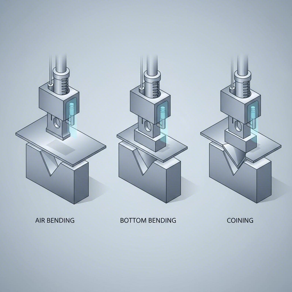
Air Bending Versus Bottom Bending
These two methods represent the workhorses of sheet metal folding operations. Understanding their differences helps you specify the right approach for your project's tolerance and cost requirements.
Air Bending: Flexibility and Efficiency
Air bending is the most common CNC bending method used today. Here's why: the punch pushes the sheet partway into a V-die, contacting only the punch tip and the die's top edges—never bottoming out completely.
What makes this technique so versatile? The punch depth alone controls your final bend angle. Go deeper for sharper angles, shallower for gentler bends. This means one die can produce multiple angles—dramatically reducing tooling costs and setup times.
- Best for: Prototypes, small batches, parts requiring varied angles, cost-sensitive production runs
- Advantages: Lower forming force required, reduced tooling investment, extended die life due to minimal contact
- Trade-offs: Higher springback (exceeding 5° in harder materials like 6061-T6 aluminum), angle accuracy depends heavily on machine repeatability
Key insight: Air bending's flexibility comes with a precision cost. Small variations in stroke depth or material thickness directly affect your final angle.
Bottom Bending: Precision Through Full Contact
When repeatability matters more than flexibility, bottom bending delivers. The punch forces the material until it rests firmly against both die flanks, closely matching the die's fixed angle.
Unlike air bending's stroke-depth dependency, bottom bending achieves accuracy through complete die contact. This approach typically holds angles within ±0.5°—significantly tighter than air bending's variable results.
- Best for: Production runs requiring consistent angles, parts where springback compensation becomes problematic
- Advantages: Better angle consistency, reduced springback (typically 1-2°), sharper corner definition
- Trade-offs: Requires dedicated dies for each bend angle, higher forming force, increased tooling costs
Coining: Maximum Precision Through Compression
Imagine stamping Lincoln's profile onto a penny—that's the principle behind coining. This high-pressure method compresses material through its full thickness, causing permanent plastic deformation that virtually eliminates springback.
The punch applies 5 to 8 times the force used in air bending, literally "stamping" the material into its final shape. The result? Exact angles with almost zero elastic recovery.
- Best for: Critical tolerance applications, hard temper materials, small-radius bends requiring zero springback
- Advantages: Highest precision available, excellent repeatability, no overbending compensation needed
- Trade-offs: Highest tonnage requirements, accelerated tool wear, material thinning of 3-10% in the bend zone, impractical for thicker sheets without heavy-duty presses
| Feature | Air Bending | Bottom Bending | Coining |
|---|---|---|---|
| Force Required | Low | Medium | High |
| Springback | High | Low | Very Low |
| Angle Accuracy | Moderate | Good (±0.5°) | Excellent |
| Tooling Flexibility | High | Low | Low |
| Tool Wear | Low | Moderate | High |
| Setup Time | Short | Medium | Long |
Specialized Forming Methods Explained
Sheet metal folding handles flat stock beautifully—but what about tubes, pipes, and large-radius curves? These applications demand specialized techniques that prevent collapse, wrinkling, and other defects that plague conventional approaches.
Rotary Draw Bending: Precision for Tubes and Pipes
When you need consistent, tight-radius bends in tubing, rotary draw bending is your go-to method. The system clamps the tube to a rotating former (bend die), then "draws" it around the former's radius using hydraulic or electric power.
This technique produces sharp bends while maintaining accuracy and consistency—essential for hydraulic lines, structural frames, and machinery components where precision truly matters.
- Best for: Exhaust systems, handrails, roll cages, furniture frames, hydraulic tubing
- Key advantage: Achieves tighter radii than compression bending without buckling or breaking
Mandrel Bending: Preventing Tube Collapse
Here's a common problem: bend a thin-walled tube too aggressively, and the inside wall collapses, wrinkles, or kinks. Mandrel bending solves this by inserting a segmented support rod inside the tube during forming.
The mandrel follows the contour shape, supporting the tube's interior and maintaining its round cross-section throughout the bend. This prevents flattening, wrinkling, and collapsing that would otherwise reduce flow efficiency and structural integrity.
- Best for: Thin-walled tubes, high-pressure applications, parts requiring smooth internal surfaces for fluid flow
- Key advantage: Maintains tube roundness and wall thickness even in aggressive radius bends
Roll Bending: Creating Curves and Cylinders
Need a sweeping architectural curve rather than a sharp angle? Roll bending passes material through a series of rollers that gradually shape it into consistent arcs, rings, or cylindrical forms.
Unlike rotary draw bending's fixed-radius approach, roll bending creates smooth, flowing curves. The technique works on tubes, bars, and sheet metals alike—making it versatile for architectural and structural applications.
- Best for: Architectural arches, vehicle rims, tank shells, spiral staircases, large-radius structural curves
- Limitations: Less effective with very thick walls or certain materials like stainless steel; not suitable for tight-radius bends
Selecting the right bending technique isn't guesswork—it's a strategic decision based on your part's geometry, material properties, and tolerance requirements. Armed with this understanding, you're ready to explore how different metals respond to these forming forces, which we'll cover next.
Material Selection and Bending Behavior
You've mastered the techniques—now imagine applying them to the wrong material. That pristine aluminum sheet cracks at the bend line. Your stainless steel panel springs back 15 degrees past target. Suddenly, technique expertise means nothing without understanding how each metal behaves under bending forces.
Here's what most fabrication guides skip: every metal has a unique personality when you try to bend it. Some cooperate beautifully. Others fight back with cracking, excessive springback, or unpredictable results. Knowing these behaviors before you start saves material, time, and frustration.
How Different Metals Respond to Bending Forces
When force pushes metal beyond its elastic limit, permanent deformation occurs. But the journey from flat stock to formed part varies dramatically depending on what's on your workbench.
Aluminum: Lightweight but Temperamental
Aluminum sheet bends easily—sometimes too easily. Its low yield strength means less force required, making it ideal for manual operations or lighter-duty equipment. But here's the catch: push the radius too tight, and aluminum can crack if over-stressed, especially in harder tempers like T6.
When considering how to bend aluminum sheet metal successfully, remember these characteristics:
- Springback rate: Typically 5-15% of the initial bend angle—lower than steel but still requires compensation
- Minimum bend radius: Generally 1x to 2x material thickness for softer alloys; harder tempers need larger radii
- Work hardening: Multiple bends in the same area increase brittleness and cracking risk
- Best practice: Use annealed (O temper) aluminum for complex forms, then heat-treat to desired hardness afterward
Mild Steel: The Predictable Performer
There's a reason mild steel dominates fabrication shops worldwide. It offers predictable bending with good formability, tolerating tighter radii than many alternatives. The material's ductility allows significant deformation before cracking becomes a concern.
Cold-rolled mild steel typically exhibits springback rates ranging from 10% to 20% of the initial bend angle. While this requires overbending compensation, the consistency makes production planning straightforward.
- Springback rate: 10-20%, higher than aluminum but highly consistent
- Minimum bend radius: Can achieve 0.5x to 1x material thickness in most applications
- Grain sensitivity: Cold-rolled steel shows pronounced grain direction; bend orientation matters
- Best practice: Position bend lines perpendicular to rolling direction when possible
Stainless Steel: Strong but Stubborn
Stainless steel sheet demands respect. Its higher yield strength requires substantially more forming force—often 50% greater than mild steel of equivalent thickness. And after you've applied that force? Expect aggressive springback that can exceed 20% in some alloys.
The material's higher risk of springback means fabricators must overbend significantly or use bottoming/coining techniques to achieve target angles. Additionally, stainless steel bending generates more heat, potentially affecting surface finish and corrosion resistance in the bend zone.
- Springback rate: 15-25%, requiring aggressive compensation strategies
- Minimum bend radius: Typically 1x to 1.5x material thickness; tighter bends risk cracking
- Grain direction: Often difficult or impossible to identify; treat as unpredictable
- Best practice: Use bottoming dies or coining for precision applications; account for higher tonnage requirements
Brass and Copper: Ductile but Quick to Harden
These non-ferrous metals bend beautifully—initially. Their excellent ductility allows intricate forms and tight radii without immediate cracking. However, brass and copper work-harden quickly, meaning each successive bend increases material hardness and reduces remaining formability.
Springback rates for brass and copper typically fall in the 5% to 15% range—similar to aluminum. This predictability makes them excellent choices for decorative applications, electrical components, and plumbing fittings.
- Springback rate: 5-15%, manageable with standard compensation
- Minimum bend radius: Can achieve very tight radii (0.5x thickness) in annealed condition
- Work hardening: Significant—annealing between operations may be necessary for multi-bend parts
- Best practice: Plan bend sequences carefully; minimize rework that adds stress to previously formed areas
Grain Direction and Bend Quality
Ever notice how wood splits more easily along the grain than across it? Metals exhibit similar behavior—though less obvious to the eye. During rolling operations at the mill, metal develops a directional grain structure that profoundly affects bending outcomes.
When your bend line runs parallel to the grain direction (bending "with" the grain), you're essentially trying to pull those aligned grain boundaries apart. The result? Greater chance of cracking, especially with tight radii or harder tempers.
Conversely, bending perpendicular to the grain ("across" or "transverse") creates stronger bends with significantly reduced cracking risk. The grain boundaries support each other rather than separating under tension.
Critical rule: Bending across the grain produces stronger bends that can hold smaller inside radii. Bending with the grain increases cracking probability, particularly as bend radius decreases.
Not all materials exhibit equal grain sensitivity. Copper has no grain; hot-rolled pickled and oiled (HRP&O) has some; and in mild cold-rolled steel, the grain can be quite pronounced. Stainless steel often makes grain identification difficult or impossible.
When grain direction cannot be controlled, compensate by:
- Increasing bend radius to reduce outer-surface tension
- Using annealed material and post-forming heat treatment
- Specifying smaller grain size material (higher quality, better consistency)
- Adding slightly more material allowance for potential scrap
Material Comparison for Bending Metal Applications
Choosing the right material means balancing formability, strength, cost, and application requirements. This comparison helps you match metal characteristics to your project needs:
| Material | Bendability | Springback | Typical Applications | Key Considerations |
|---|---|---|---|---|
| Aluminum (3003, 5052) | Excellent | 5-15% | Enclosures, HVAC, aerospace brackets, architectural panels | Cracks if radius too tight; softer tempers bend easier; lightweight advantage |
| Mild Steel (A36, 1018) | Very Good | 10-20% | Automotive brackets, structural components, machinery guards | Predictable behavior; grain direction affects results; requires rust protection |
| Stainless Steel (304, 316) | Moderate | 15-25% | Food equipment, medical devices, marine hardware, architectural trim | High force required; aggressive springback; heat generation; corrosion resistant |
| Brass (C260, C270) | Excellent | 5-15% | Electrical connectors, decorative hardware, plumbing fittings | Work hardens quickly; may need inter-operation annealing; excellent appearance |
| Copper (C110, C122) | Excellent | 5-15% | Electrical busbars, heat exchangers, roofing, artistic metalwork | No grain direction concerns; work hardens; superior electrical/thermal conductivity |
Understanding material behavior transforms bending sheet metal from guesswork into predictable manufacturing. With this foundation, you're ready to apply design guidelines that account for these characteristics—ensuring your parts bend successfully the first time.
Design Guidelines for Successful Metal Bending
So you've selected your material and understand how it behaves—but here's where many projects stumble. Even the perfect material choice fails when design specifications ignore manufacturing realities. How do you bend sheet metal without cracking, warping, or producing parts that don't match your CAD model?
The answer lies in Design for Manufacturability (DFM)—a set of principles that bridge the gap between what looks good on screen and what actually works in production. Think of DFM as the translator between your engineering intent and the physical constraints of metal forming equipment.
Let's explore the critical rules that separate successful sheet metal bend designs from costly manufacturing failures.
Bend Radius Rules for Different Thicknesses
Imagine folding a piece of cardboard too sharply—the outer surface cracks and tears. Metal behaves similarly. When you bend metal, the outer surface stretches under tension while the inner surface compresses. Push the radius too tight, and that outer surface exceeds its tensile limit.
Here's the fundamental rule: the inside bend radius should equal or exceed the material thickness for most metals. This 1:1 ratio represents the safe starting point, though specific materials may require adjustments.
| Material | Minimum Inside Bend Radius | Notes |
|---|---|---|
| Aluminum (soft temper) | 1× material thickness | Harder tempers like T6 may require 2× or greater |
| Mild Steel | 0.5× to 1× material thickness | Cold-rolled offers tighter radii than hot-rolled |
| Stainless Steel | 1× to 1.5× material thickness | Higher springback requires overbending compensation |
| Brass/Copper | 0.5× to 1× material thickness | Annealed condition allows tightest radii |
Why does thickness matter so much? According to Xometry's engineering resources, thicker sheets require larger bend radii because bending induces tensile and compressive stresses—thicker sheets are less flexible and more prone to cracking if the bend radius is too small.
Business insight: If you design all your bends to use the same radius, your fabricator can use a single tool for every fold. This reduces setup time and lowers your per-part cost.
The relationship between thickness and bending parameters extends beyond radius alone. As material thickness increases, V-die openings must widen, bending force requirements climb, and minimum flange lengths grow accordingly.
Designing Parts That Bend Successfully
Knowing the minimum radius gets you started—but successful parts require attention to several interconnected design elements. How do you bend metal without distorting nearby features or creating stress concentrations that lead to failure?
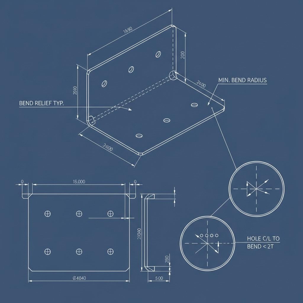
Bend Relief Cuts: Preventing Corner Tears
When a bend line meets a flat edge, the metal attempts to separate at the corner. Without intervention, you'll see tearing, distortion, or ugly stress marks that compromise both appearance and structural integrity.
The solution? Add a small rectangular or circular cut-out—called a bend relief—at the end of your bend lines. According to Norck's DFM guidelines, this simple feature guarantees a clean, professional finish that won't make the part break due to pressure.
- Relief width: At least equal to material thickness
- Relief depth: Extends slightly beyond the bend line
- Shape options: Rectangular for maximum material removal, circular for reduced stress concentration
Hole and Edge Positioning: The 2× Rule
Place a hole too close to a bend line, and something unfortunate happens—the hole stretches into an oval. Screws won't fit. Pins won't align. Your assembly fails before it begins.
The simple rule from established DFM practices: keep holes a minimum of two times the material thickness from any bend location. This buffer zone prevents deformation from the bending process from affecting your precision features.
The same principle applies to edges—maintain adequate distance between bend lines and part perimeters to prevent unwanted deformation or material tearing.
K-Factor: The Key to Accurate Flat Patterns
Here's a concept that separates amateur designs from production-ready parts. When metal bends, the outer surface stretches while the inner surface compresses. This means your final bent part has a different total length than the flat pattern you started with.
The K-factor quantifies this behavior. As explained by SendCutSend's technical resources, K-factor is the ratio between the material thickness and the neutral axis—that invisible line running through the part where material neither stretches nor compresses during bending.
Why does this matter for your designs? Because the K-factor determines the bend allowance—how much material "disappears" into each bend. Get this wrong, and your flanges end up too long or too short.
- Typical K-factor range: 0.3 to 0.5 for most materials and processes
- Lower K-factors: Indicate the neutral axis shifts more toward the inside of the bend
- Higher K-factors: Suggest less neutral axis shift, common with softer materials or larger radii
The good news? Most CAD software and fabrication partners handle K-factor calculations automatically. However, understanding the concept helps you recognize when flat pattern dimensions need verification—especially for critical tolerance applications.
Flange Length Requirements
Your bending equipment needs something to grab. If the flange—the portion being bent upward—is too short, the machine can't grip it properly. The result? Inconsistent angles, tool slippage, or damaged parts.
The rule from manufacturing best practices: make your flange at least 4 times the material thickness. Shorter flanges require custom, expensive tooling that can double production costs.
Essential DFM Guidelines for Metal Bending
When preparing your next sheet metal bend design, run through this checklist to ensure manufacturability:
- Maintain minimum bend radius: Inside radius ≥ material thickness for most metals; consult material-specific tables for precision applications
- Add bend reliefs: Include relief cuts where bend lines meet edges to prevent tearing and stress concentration
- Position holes correctly: Keep all holes at least 2× material thickness away from bend lines
- Ensure adequate flange length: Design flanges at least 4× material thickness to allow proper tool engagement
- Consider grain direction: Orient bends perpendicular to rolling direction when possible to minimize cracking risk
- Standardize bend radii: Use consistent radii throughout your design to minimize tooling changes and reduce costs
- Account for springback: Work with your fabricator to determine appropriate overbend compensation for your material
- Verify K-factor calculations: Confirm flat pattern dimensions with your manufacturer, especially for tight-tolerance parts
- Use standard hole sizes: Specify common drill bit dimensions (5mm, 6mm, 1/4") to avoid custom tooling charges
- Allow tolerance flexibility: Where precision isn't critical, accept standard sheet metal tolerances to reduce inspection costs
Following these guidelines transforms how you approach custom metal bending projects. Rather than discovering problems during production, you'll catch potential issues at the design stage—when changes cost nothing but a few mouse clicks. With your design optimized for manufacturability, the next consideration becomes choosing between CNC precision and manual forming methods.
CNC Bending Versus Manual Forming Processes
Your design is optimized. Your material is selected. Now comes a fundamental question that directly impacts cost, precision, and lead time: should your parts run through a computer-controlled CNC press brake or be formed manually by a skilled operator?
This isn't just a technical decision—it's a strategic one. The wrong choice means paying premium prices for simple parts or accepting inconsistent results on precision components. Let's break down exactly when each approach delivers the best value.
CNC Press Brake Precision and Repeatability
Picture this: a CNC sheet metal bender receives your CAD file, calculates the exact punch depth for each bend, compensates for material springback automatically, and produces identical parts hour after hour. That's the power of computer-controlled forming.
CNC sheet metal bending uses programmable press brakes where accuracy is set according to a computer program. Once your operator enters the correct specifications, the machine executes each bend with mechanical precision—eliminating the variability inherent in human-controlled processes.
What makes metal CNC forming so effective for production runs?
- Consistent angles across batches: The first part and the thousandth part match within tight tolerances—typically ±0.5° or better
- Complex multi-bend sequences: Modern controllers manage intricate programs with dozens of bends, automatically adjusting backstop positions between operations
- Springback compensation: Advanced systems measure actual bend angles and automatically adjust punch depth to hit target specifications
- Reduced operator fatigue errors: Unlike manual operations where worker efficiency decreases with time, CNC machines maintain the same speed and accuracy throughout extended production runs
The technology also enables capabilities that manual methods simply can't match. Sheet metal CNC operations can store hundreds of programs, allowing instant changeovers between different part numbers. Need to run 50 of part A, then switch to 200 of part B? The operator loads the program and resumes production in minutes.
Quality insight: With CNC bending, ongoing checks remain essential. Even with programmed precision, monitoring cumulative tolerances across multiple folds prevents issues from compounding—especially critical for complex parts requiring 8 or more bends.
Thickness Capabilities and Tonnage Requirements
CNC press brakes aren't unlimited—every machine has a rated tonnage that determines its maximum bending capacity. Understanding this relationship helps you match your project to appropriate equipment.
Typical CNC sheet metal cutting and bending operations handle material ranging from thin gauge (0.5mm) up to thick plate (25mm or more). However, capacity depends on several interconnected factors:
- Machine tonnage: Expressed in tons of force, ranging from 40 tons for light-duty machines to 1,000+ tons for heavy plate work
- Material type: Stainless steel requires approximately 50% more force than mild steel of equivalent thickness; aluminum needs considerably less
- Bend length: Longer bends require proportionally more tonnage—a 2-meter bend needs roughly twice the force of a 1-meter bend
- V-die opening: Wider dies reduce force requirements but affect minimum achievable bend radius
Here's a practical example from industry calculations: bending 3mm stainless steel over a 2-meter length requires approximately 75 tons of capacity—including a 20% safety margin. Attempting this on a 50-ton machine would stall the equipment or damage tooling.
The exponential relationship between thickness and force catches many people off guard. Double the material thickness, and force requirements quadruple—not double. This t² relationship means a 6mm sheet needs roughly four times the tonnage of 3mm material, assuming identical conditions.
When Manual Bending Makes Sense
Despite CNC's advantages, manual press brakes haven't disappeared from fabrication shops. In specific situations, they remain the smarter choice.
Manual forming involves an operator physically guiding the workpiece, positioning it against backstops, and controlling the bending stroke through foot pedals or hand controls. As described by industry sources, the worker picks up the sheet, slides it between the upper and lower dies until it meets the backstop, then lowers the upper die to form the bend.
This hands-on approach excels in several scenarios:
- Prototypes and one-off parts: Programming a CNC machine takes time. For a single bracket or test piece, an experienced operator forms it faster manually
- Simple geometries: Parts with one or two basic bends don't benefit from CNC's complex sequencing capabilities
- Budget-sensitive shops: Manual press brakes cost significantly less due to their simpler construction, making them accessible for smaller operations
- Operator judgment applications: Some artistic or custom work benefits from real-time human decision-making during forming
However, manual methods carry inherent limitations. Accuracy depends primarily on operator skill level—any mistake could render the part unusable. Working with large, heavy sheets becomes physically demanding and often requires multiple people. Extended production runs lead to fatigue-induced errors that compound over time.
Comparing the Two Approaches
| Factor | CNC Press Brake | Manual Press Brake |
|---|---|---|
| Accuracy Source | Computer program | Operator skill |
| Repeatability | Excellent across runs | Variable with fatigue |
| Complex Sequences | Handles multi-bend programs | Limited capability |
| Setup Time | Longer initial programming | Quick for simple parts |
| Equipment Cost | Higher investment | Lower initial cost |
| Operating Cost | Lower per-part at volume | Higher labor intensity |
| Best For | Production runs, tight tolerances | Prototypes, simple one-offs |
The decision ultimately comes down to volume, complexity, and tolerance requirements. For most production applications—especially those requiring consistent angles across dozens or hundreds of parts—CNC sheet metal bending delivers superior results at lower per-piece costs. Manual methods remain valuable for quick-turn prototypes and simple forming operations where programming time would exceed actual production time.
With forming methods understood, the next step is seeing how these capabilities translate into real-world applications across different industries—each bringing unique requirements for tolerance, finish, and performance.
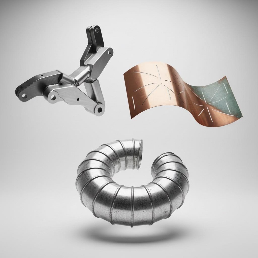
Industry Applications for Custom Bent Metal Parts
Understanding bending techniques and equipment is valuable—but where does all this precision forming actually end up? The answer spans nearly every sector of modern manufacturing. From the chassis bracket holding your car's suspension together to the sleek curved facade on a downtown high-rise, custom metal bending touches countless products you interact with daily.
What makes this particularly interesting is how dramatically requirements differ across industries. A decorative architectural panel prioritizes aesthetics over tight tolerances, while an automotive suspension component demands precise angles that affect vehicle safety. Let's explore how steel fabricators and metal benders serve these diverse needs.
Automotive and Transportation Components
When you're searching for metal fabricators near me for automotive applications, you're entering one of the most demanding sectors for custom bent parts. Vehicle manufacturers require components that withstand constant vibration, temperature extremes, and safety-critical loading conditions.
Steel bending for automotive applications typically involves:
- Chassis brackets: These mounting points connect suspension systems, engine components, and body panels to the vehicle frame. Tolerance requirements often fall within ±0.5mm to ensure proper bolt hole alignment during assembly
- Suspension components: Control arms, spring mounts, and stabilizer bar brackets must maintain precise angles to preserve vehicle handling characteristics
- Structural reinforcements: Crush zones, door intrusion beams, and rollover protection elements require predictable deformation behavior in crash scenarios
- Exhaust system hangers: Metal bent brackets support exhaust components while isolating vibration from the passenger compartment
- Battery and electronics enclosures: Electric vehicles demand precisely formed housings that protect sensitive components while managing thermal loads
The automotive sector's tolerance requirements reflect its safety-critical nature. According to industry manufacturing standards, automotive brackets must meet precise tolerance specifications to ensure components match perfectly during assembly—preventing repairs, production delays, or safety issues.
Finish specifications also vary by application. Interior brackets may accept standard mill finish, while visible components require powder coating or electroplating for corrosion resistance and appearance.
Architectural and Interior Applications
Step outside the factory floor, and custom metal bending transforms into an art form. Architectural applications prioritize visual impact alongside structural performance—creating opportunities for creative expression that industrial components rarely permit.
As noted by architectural metalworking specialists, steel bending enables architects and designers to push creative boundaries while maintaining structural integrity. This balance between aesthetics and engineering defines architectural metalwork.
Common architectural applications include:
- Decorative facade panels: Curved and angular cladding elements define modern building exteriors while providing weather protection. Sheet metal bending allows smooth, flowing designs that enhance aerodynamics and visual appeal
- Railings and balustrades: Bent sheet metal creates custom handrails with curved and sculptural designs that add elegance while maintaining safety and durability
- Decorative screens and room dividers: Perforated and curved panels enhance aesthetics while improving airflow and lighting within spaces
- Arched doorways and window frames: Custom curved metal frames add sophistication to high-end residential homes, boutique hotels, and historical renovations
- Sculptural installations: Artists and designers transform rigid materials into dynamic forms, creating visually captivating pieces for urban spaces and luxury interiors
- Custom furniture elements: Metal chairs, tables, and shelving units provide strength and modern aesthetic appeal
Tolerance requirements in architectural work differ significantly from industrial applications. While a ±2mm variance might be acceptable for a decorative panel, the same variance could be unacceptable for a precision machine component. However, surface finish demands often exceed industrial standards—scratches or tool marks visible on a facade panel represent unacceptable defects.
Industrial and Commercial Applications
Between automotive precision and architectural aesthetics lies the broad category of industrial applications. These components prioritize function and durability, often operating in harsh environments where failure carries serious consequences.
According to custom fabrication specialists, components built for industrial environments face enormous stresses, extreme temperatures, and long-term wear. For these parts to function correctly, they must start with solid fundamentals in their forming processes.
Industrial applications for metal bent components include:
- HVAC ductwork: Rolled and formed components guide airflow, manage pressure changes, and connect various sections of piping or equipment. Cylindrical ducts, cone reducers, and curved elbows must meet exact specifications for airflow efficiency
- Electrical enclosures: Sheet metal housings protect sensitive electronics from dust, debris, weather, and mechanical damage. Precise bends ensure proper sealing and mounting
- Machine guards: Safety enclosures around rotating equipment, pinch points, and hazardous areas require durable formed metal that withstands impact
- Equipment housings: Customized housings shield electronics, compressors, or sensitive controls in industrial settings
- Storage tanks and pressure vessels: Rolled shells joined through high-strength welding hold water, chemicals, grains, or gases while maintaining structural integrity under load
- Conveyor system components: Brackets, guides, and structural supports keep material handling systems aligned and operational
- Equipment bases and frames: A mix of rolled and formed parts supports motors, bearings, or rotating machinery while distributing weight and resisting deformation
Industrial tolerance requirements typically fall between automotive precision and architectural flexibility. A machine guard might accept ±1mm variance, while equipment mounting brackets may need ±0.5mm to ensure proper alignment. Finish specifications focus on corrosion protection rather than aesthetics—powder coating, galvanizing, or specialized coatings that extend service life in demanding environments.
Matching Tolerances to Application Requirements
The diversity of applications means there's no universal standard for "acceptable" tolerance or finish quality. Understanding these differences helps you specify appropriate requirements—avoiding both over-engineering that increases costs and under-specification that causes field failures.
| Industry Sector | Typical Angle Tolerance | Typical Dimensional Tolerance | Primary Finish Concerns |
|---|---|---|---|
| Automotive | ±0.5° to ±1° | ±0.25mm to ±0.5mm | Corrosion resistance, assembly fit |
| Architectural | ±1° to ±2° | ±1mm to ±2mm | Surface appearance, seamless joints |
| Industrial | ±0.5° to ±1.5° | ±0.5mm to ±1mm | Durability, chemical resistance |
| Consumer Products | ±1° to ±2° | ±0.5mm to ±1mm | Aesthetics, user safety |
These ranges represent starting points—specific applications may demand tighter or looser specifications based on functional requirements. A bracket that positions a sensor might need ±0.25mm precision, while a decorative cover on the same equipment accepts ±2mm without issue.
Recognizing where your components fall on this spectrum helps you communicate effectively with fabrication partners and make informed decisions about cost-versus-precision tradeoffs. With application requirements understood, the next step is learning how to work effectively with service providers who can translate your designs into finished parts.
Working with Metal Bending Service Providers
You've designed a part optimized for manufacturability. You understand material behavior and have selected the right bending approach. Now comes a critical question many engineers overlook: how do you actually work with metal bending services to turn that design into physical components?
The difference between a frustrating experience and a seamless partnership often comes down to preparation. Metal bending shops receive hundreds of inquiries—those who provide complete, well-organized information move to the front of the queue and receive more accurate quotes. Let's walk through exactly what successful collaboration looks like.
Preparing Your Design Files for Bending
Imagine a fabricator receiving your inquiry with nothing but a rough sketch and the phrase "quote needed ASAP." They'll either delay your request while chasing missing details or provide a padded estimate to cover unknowns. Neither outcome serves your project timeline or budget.
According to Approved Sheet Metal's research, receiving a 3D CAD file at the time of an RFQ allows shops to turn around formed sheet metal prototypes in just 3 days—compared to significantly longer lead times when only 2D drawings are provided.
Why do CAD files accelerate the process so dramatically?
- Full visibility: 3D models enable fabricators to see every angle of your part, zooming in on details that drawings can't fully convey
- Automated programming: Files integrate directly with CNC bending services equipment, eliminating manual data entry that introduces errors
- Design ambiguity resolution: When questions arise, fabricators can take their own dimensions rather than waiting for your clarification
- Simplified complexity: Complicated assemblies become easier to visualize, helping identify potential misalignments before production begins
When preparing your submission for sheet metal bending near me providers, include these file formats for optimal results:
- .STEP or .IGES: These neutral formats work across most CAD platforms while preserving geometric integrity
- .SLDPRT/.SLDASM: If using SolidWorks, native files retain material thickness, bend features, and configuration data
- .DXF: Useful for 2D flat patterns, but pair with a PDF drawing or 3D file since DXF lacks thickness and bend angle information
Pro tip: Always include revision labels in your file names (e.g., Bracket_RevB.step) to avoid confusion when designs evolve during the quoting process.
What to Expect from Quote to Delivery
Understanding the typical workflow helps you set realistic expectations and prepare the right information at each stage. Most sheet metal fabrication projects follow a predictable path from initial inquiry to final delivery.
Step 1: Submit Your Inquiry Package
Beyond CAD files, metal bending shops need specific details to generate accurate pricing. According to LS Manufacturing's quoting guidelines, a complete inquiry should include:
- Material type and grade: Specify exactly what you need (e.g., 304 stainless steel, 6061-T6 aluminum, A36 mild steel)
- Material thickness: Critical for tonnage calculations and tooling selection
- Quantity requirements: Include both initial order size and anticipated annual volumes—unit pricing varies significantly with batch size
- Tolerance specifications: Call out critical dimensions versus those accepting standard tolerances
- Surface finish requirements: Powder coating, electroplating, anodizing, or raw finish—each carries different cost implications
- Delivery timeline: Rush orders cost more; realistic schedules save money
Step 2: Receive DFM Feedback
Quality metal bending services don't just quote your design as-submitted. They analyze it for manufacturability and suggest improvements. This Design for Manufacturability (DFM) review can dramatically impact your costs.
In one documented case, engineering analysis reduced bending steps from seven to four by tweaking a design detail—immediately cutting per-part cost by 18% without affecting functionality.
For automotive applications where certified quality matters, partners offering comprehensive DFM support—like Shaoyi (Ningbo) Metal Technology with their 12-hour quote turnaround and 5-day rapid prototyping—streamline this critical feedback loop considerably.
Step 3: Quote Review and Approval
A professionally prepared quote should provide transparent cost breakdowns rather than a single bottom-line number. Look for itemized details covering:
- Material costs (including scrap allowance)
- Processing fees (cutting, bending, secondary operations)
- Surface treatment costs
- Tooling charges (if applicable)
- Shipping and packaging
This transparency enables informed decisions about where to optimize. Perhaps a material substitution saves 15%, or consolidating surface treatment steps reduces processing time.
Step 4: Prototyping (When Needed)
For complex parts or new designs, prototyping validates your specifications before committing to production quantities. Rapid prototyping capabilities—some providers deliver samples in as few as 5 days—allow you to verify fit, function, and appearance before investing in full production runs.
Step 5: Production and Quality Verification
During production, reputable shops implement quality checks throughout the process rather than only at final inspection. For automotive components, this becomes especially critical.
Quality Certifications That Matter
When sourcing parts for regulated industries, certifications provide assurance that your supplier maintains documented quality systems. For automotive applications, one certification stands above others: IATF 16949.
According to Xometry's certification resources, IATF 16949 is a quality management system specifically designed for automotive manufacturers. Built on the ISO 9001 framework, it focuses on creating consistency, safety, and quality across automotive products.
What does IATF 16949 certification actually mean for your supply chain?
- Documented processes: The supplier maintains verified procedures for every manufacturing step
- Defect prevention focus: Systems are designed to limit defects, reducing waste and ensuring consistent output
- Customer and regulatory compliance: The framework ensures suppliers meet both customer requirements and industry regulations
- Continuous improvement: Certified organizations commit to ongoing quality enhancement
For chassis, suspension, and structural components where precision directly affects vehicle safety, working with IATF 16949-certified suppliers like Shaoyi Metal Technology provides documented quality assurance that protects both your products and your reputation.
Beyond automotive-specific certifications, also verify:
- ISO 9001: General quality management certification applicable across industries
- AS9100: For aerospace applications requiring additional traceability and documentation
- Material certifications: Mill test reports confirming material composition meets specifications
The partnership you establish with your metal bending service provider extends beyond a single transaction. Suppliers who invest in comprehensive DFM support, rapid prototyping, and certified quality systems become valuable extensions of your engineering team—catching issues early, suggesting improvements, and delivering consistent results project after project.
Even with ideal partnerships, challenges arise during production. Understanding common bending defects—and how to prevent them—prepares you to address issues before they become costly problems.
Troubleshooting Metal Bending Challenges
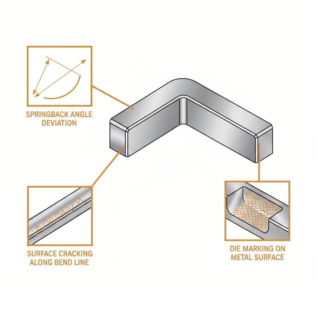
Even with optimized designs and reliable partners, things can go wrong during production. A bent sheet metal component springs back past its target angle. Cracks appear along bend lines. Surface marks from tooling mar an otherwise perfect part. These frustrations affect both newcomers and experienced professionals—but understanding why defects occur transforms reactive troubleshooting into proactive prevention.
Precision bending demands attention to details that aren't always obvious. The good news? Most common defects follow predictable patterns with well-established solutions. Let's explore the challenges you're most likely to encounter and exactly how to address them.
Preventing Springback and Cracking
When you bend metal, something counterintuitive happens: the material fights back. This phenomenon—called springback—occurs because metals possess elastic properties alongside their permanent (plastic) deformation characteristics. After bending forces release, the elastic component partially recovers, pushing your bend angle away from the target.
According to manufacturing research, springback happens because metal atoms move when you bend the material—and they want to return when you stop applying force. This elastic recovery can make your final shape significantly different from what you intended.
Why Springback Matters
Imagine you need a precise 90° bracket. You program your press brake for exactly 90°, run the part, and measure 87°. That 3° discrepancy might seem minor—until your bracket won't fit its mating component. Holes don't align. Assembly becomes impossible.
The consequences extend beyond fit issues:
- Parts fail quality checks and require rework
- Material waste increases when defective components get scrapped
- Production schedules slip as operators troubleshoot unexpected results
- Dimensional accuracy suffers across entire batches
Compensation Strategies That Work
The most straightforward solution? Overbend intentionally. If you know stainless steel springs back 5°, program your press brake for 95° to achieve a final 90° bend. This compensation approach can reduce springback by up to 45% when properly calibrated.
Here's a practical process for determining your overbend angle:
- Step 1: Create a test bend at your target angle using scrap material identical to your production stock
- Step 2: Measure the actual resulting angle after springback occurs
- Step 3: Calculate the difference between target and actual angles
- Step 4: Add this difference to your programmed bend angle
- Step 5: Verify with another test bend before running production
Critical principle: Springback compensation isn't guesswork—it's calculated adjustment. Always test with actual production material, since batch-to-batch variations affect elastic recovery.
Beyond overbending, technique selection significantly impacts springback. Bottoming and coining methods force material fully into the die, creating more plastic deformation and reducing elastic recovery. When learning how to bend metal sheet for precision applications, these high-pressure techniques often prove essential.
Cracking: Causes and Prevention
While springback frustrates by changing dimensions, cracking destroys parts entirely. Visible fractures along bend lines render components unusable—and unlike springback, cracking can't be corrected after the fact.
What causes metal bends to crack? Three primary factors:
- Bend radius too tight: When the outer surface stretches beyond the material's tensile limit, it fractures. Each material has a minimum achievable radius based on thickness and ductility
- Wrong grain orientation: Bending parallel to rolling direction forces grain boundaries apart, dramatically increasing crack risk. Perpendicular orientation produces stronger bends
- Work-hardened material: Previous forming operations increase brittleness. Multiple bends in the same area—or using pre-hardened stock—reduces remaining ductility
Prevention strategies address each root cause:
- Specify minimum bend radii appropriate to your material and temper
- Orient bend lines perpendicular to grain direction whenever possible
- Consider annealing between operations for complex multi-bend parts
- When bending aluminum sheet, use softer tempers (O or H32) rather than fully hardened conditions
Prevention principle: Cracking signals you've exceeded material limits. The solution isn't more force—it's redesigning the bend geometry or selecting more formable material.
Solving Common Bending Defects
Beyond springback and cracking, several other defects plague bendable sheet metal operations. Recognizing these issues—and knowing their solutions—keeps your production running smoothly.
Surface Marking and Die Marks
You've achieved the perfect angle with no cracking—but unsightly scratches, gouges, or indentations mar your part's surface. These cosmetic defects often prove unacceptable for visible components or pre-finished materials.
According to tooling specialists, die marking occurs when dies with small shoulder radii penetrate the material during bending, leaving grooves or aggressive marks as material drags over sharp edges. The problem intensifies with pre-painted stock, aluminum, stainless steel, brass, and copper—materials where surface appearance matters most.
Solutions for minimizing surface damage:
- Large shoulder radii dies: Dies with shoulder radii 1.5 times material thickness or greater prevent penetration-style gouging
- Protective films: Polyurethane sheeting or densely woven nylon "No-Mar Cloth" creates a barrier between material and tooling
- Proper die selection: Match die geometry to material type—what works for mild steel may damage stainless or aluminum
- Regular tool maintenance: Worn, nicked, or dirty dies transfer imperfections to every part they touch
Wrinkling and Inconsistent Bends
Wrinkling appears when material "bundles up" around the bend, creating overlapping folds rather than smooth curves. This defect occurs primarily in thin materials that can't resist compressive forces during forming.
Inconsistent bends—where geometry appears wavy or rippled rather than uniform—often stem from material property variations, improper die clearance, or inadequate machine maintenance.
Prototyping or simulation helps identify correct parameters before production begins. Additionally, ensuring proper die clearance and using well-maintained tooling prevents geometry variations from creeping into your parts.
Quick Reference: Defect Prevention Checklist
| Defect | Primary Causes | Prevention Strategies |
|---|---|---|
| Springback | Material elasticity, insufficient forming force | Overbend compensation, bottoming/coining techniques, proper material selection |
| Cracking | Tight radius, parallel grain, work hardening | Increase bend radius, orient perpendicular to grain, use annealed material |
| Surface Marking | Sharp die edges, metal-to-metal contact | Large-radius dies, protective films, proper tooling maintenance |
| Wrinkling | Thin material, compression forces | Proper blank holding, appropriate die clearance, prototype testing |
| Inconsistent Angles | Material variation, die clearance, machine wear | Material certification, regular calibration, preventive maintenance |
Mastering these troubleshooting fundamentals transforms how you approach custom metal bending projects. Rather than reacting to defects after they appear, you'll anticipate potential issues and design them out from the start. This proactive mindset—combined with the technical knowledge covered throughout this guide—positions you to make informed decisions when selecting your bending approach and manufacturing partner.
Choosing the Right Custom Metal Bending Solution
You've absorbed a comprehensive foundation—from bending techniques and material behaviors to design guidelines and defect prevention. Now comes the practical question: how do you translate this knowledge into a successful custom sheet metal bending project?
The answer involves three interconnected decisions. Get any one wrong, and you'll face delays, cost overruns, or parts that don't perform as intended. Get all three right, and your project flows smoothly from concept to finished components.
Matching Your Project to the Right Bending Approach
Every successful metal bending service engagement starts with honest project assessment. Before searching for metal bending shops near me or requesting quotes, work through these critical decision factors:
Material Selection Based on Application Requirements
Your operating environment dictates material choice—not the other way around. Consider:
- Corrosion exposure: Marine or outdoor applications demand stainless steel or properly coated mild steel
- Weight constraints: Aerospace and automotive applications often justify aluminum's higher material cost for weight savings
- Electrical requirements: Copper and brass excel where conductivity matters
- Cost sensitivity: Mild steel offers the best value when corrosion protection can be applied post-fabrication
Remember that material selection directly impacts achievable tolerances. According to manufacturing specialists, high-strength steels or thick stainless steel may require bottoming or coining to control springback—affecting both technique selection and cost.
Technique Selection Based on Geometry Complexity
Match your part's requirements to the appropriate forming method:
- Simple angles, lower volumes: Air bending offers flexibility and economy
- Tight tolerances (±0.3° or better): Bottoming provides improved angular consistency
- Critical precision applications: Coining delivers ±0.1° accuracy for aerospace and medical components
- Tubes and pipes: Rotary draw or mandrel bending prevents collapse and maintains cross-section
- Large-radius curves: Roll bending creates sweeping architectural forms
Provider Selection Based on Capabilities and Certifications
Your fabrication partner's capabilities must align with your project requirements. As noted by industry experts, hiring a fabricator isn't just a purchasing decision—it's a long-term investment in the performance and reliability of your products.
Evaluate potential partners against these criteria:
- Industry experience: Do they understand your sector's specific requirements and standards?
- In-house capabilities: Full-service facilities streamline production and maintain quality control
- Quality certifications: IATF 16949 for automotive, AS9100 for aerospace, ISO 9001 for general manufacturing
- Engineering support: DFM guidance reduces iterations and accelerates time-to-production
- Scalability: Can they support both prototypes and production volumes?
Next Steps for Your Custom Bending Project
Ready to move forward? Here's your action plan:
Step 1: Finalize Your Design for Manufacturability
Review your CAD files against the DFM guidelines covered earlier. Verify bend radii meet minimum requirements, holes are positioned correctly relative to bend lines, and grain direction considerations are addressed. According to DFM specialists, collaborating with manufacturers early is essential to align material attributes with both design aesthetic and functionality requirements.
Step 2: Prepare Complete Documentation
Assemble your inquiry package with:
- 3D CAD files (.STEP, .IGES, or native format)
- Material specifications including grade and thickness
- Quantity requirements (initial and projected annual volumes)
- Critical tolerance callouts
- Surface finish requirements
- Target delivery timeline
Step 3: Engage with Qualified Providers
Request quotes from fabricators whose capabilities match your requirements. For automotive applications requiring IATF 16949-certified quality, partners like Shaoyi (Ningbo) Metal Technology offer comprehensive DFM support, 5-day rapid prototyping, and 12-hour quote turnaround—accelerating your path from design to custom bent metal components.
Step 4: Leverage DFM Feedback
Don't treat fabricator feedback as criticism—treat it as collaborative optimization. Early DFM collaboration often reveals opportunities to reduce costs, improve quality, or accelerate delivery that weren't apparent during initial design.
Success principle: The best custom metal bending outcomes result from treating your fabrication partner as an extension of your engineering team, not just a vendor fulfilling orders.
Armed with the knowledge from this guide—techniques, materials, design guidelines, and troubleshooting strategies—you're positioned to source metal fabrication near me with confidence. Whether you're developing automotive chassis components, architectural panels, or industrial enclosures, the fundamentals remain consistent: match material to application, select appropriate techniques for your geometry, and partner with fabrication shops near me that bring both capability and collaboration to every project.
Frequently Asked Questions About Custom Metal Bending
1. How much does it cost to have metal bent?
Custom metal bending costs vary based on quantity, complexity, and material. Volume pricing typically ranges from $1.00-$3.00 per bend, with higher quantities receiving lower per-bend rates. Factors affecting cost include material type (stainless steel requires more force than aluminum), number of bends per part, tolerance requirements, and surface finish specifications. For automotive applications requiring IATF 16949-certified quality, partnering with manufacturers like Shaoyi Metal Technology can optimize costs through comprehensive DFM support and efficient production processes.
2. What is metal bending called?
Metal bending is also known as sheet metal bending, press brake forming, or metal forming. The process involves applying controlled force to deform metal using machines called press brakes with punch and die tooling. Specific techniques include air bending, bottom bending, coining, rotary draw bending, mandrel bending, and roll bending—each suited to different applications, materials, and precision requirements.
3. What materials can be custom bent and how do they behave differently?
Common bendable materials include aluminum (easy to bend but cracks if radius is too tight), mild steel (predictable with good formability), stainless steel (requires 50% more force with higher springback), and brass/copper (excellent ductility but work-harden quickly). Each material has unique springback rates—aluminum at 5-15%, mild steel at 10-20%, and stainless steel at 15-25%. Material selection should match your application's corrosion resistance, weight, and strength requirements.
4. What is the minimum bend radius for sheet metal?
The general rule states that inside bend radius should equal or exceed material thickness. For soft aluminum alloys, 1x material thickness works well, while harder tempers may require 2x or greater. Mild steel achieves 0.5x to 1x thickness, stainless steel needs 1x to 1.5x, and annealed brass/copper can reach 0.5x thickness. Bending perpendicular to grain direction also allows tighter radii without cracking.
5. How do I prepare design files for custom metal bending services?
Submit 3D CAD files in .STEP or .IGES formats for fastest processing—shops can turn around formed prototypes in 3 days versus longer lead times with 2D drawings only. Include material type and grade, thickness, quantity requirements, critical tolerance callouts, surface finish specifications, and delivery timeline. For automotive components, working with IATF 16949-certified partners offering DFM support ensures designs are optimized before production begins.