 Small batches, high standards. Our rapid prototyping service makes validation faster and easier —

Essential Draft Angle Requirements for Die Casting Design

TL;DR
A draft angle in die casting is a slight taper applied to a part's surfaces that are parallel to the mold's direction of pull. This design feature, typically ranging from 0.5 to 2 degrees, is critical for ensuring the part can be easily ejected from the die without damage to the component or the tooling. The specific draft angle requirement depends on the alloy being cast, the depth of the feature, and the surface texture, with abrasive materials like aluminum generally requiring a larger angle than zinc.
The Fundamental Role of Draft Angles in Die Casting
In the precision-driven world of die casting, every design choice impacts manufacturability, quality, and cost. Among the most critical of these is the draft angle. A draft angle is a taper or slope intentionally designed into the vertical walls of a casting. All surfaces parallel to the direction the die opens must have a draft to allow the solidified part to be smoothly removed from the mold. Without it, the part would scrape against the mold wall during ejection, leading to significant friction and potential damage.
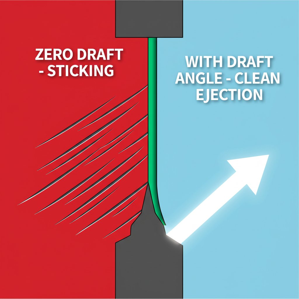
The primary purpose of a draft angle is to facilitate easy and clean part ejection. As the molten metal cools and solidifies, it shrinks and grips tightly onto the die's cores and internal features. A tapered surface breaks this adhesion cleanly, reducing the force required for ejection. According to the North American Die Casting Association (NADCA), this simple feature is essential for preventing defects and ensuring a high-quality surface finish. Forcing a part with vertical walls (zero draft) out of a mold can cause drag marks, scratches, and even structural damage to the casting. It can also cause excessive wear on the expensive die-casting tool itself, leading to costly repairs and production downtime.
Incorporating an appropriate draft angle offers several key benefits that contribute to an efficient and reliable manufacturing process. These advantages include:
- Improved Part Ejection: The most immediate benefit is a reduction in the force needed to eject the part, minimizing the risk of the part sticking in the mold.
- Enhanced Surface Quality: By preventing scraping and dragging during removal, draft angles ensure the cast part has a smooth, defect-free surface finish, reducing the need for secondary finishing operations.
- Extended Tool Life: Reduced friction and ejection force mean less wear and tear on the mold's cavity and core surfaces, significantly prolonging the operational life of the die.
- Increased Production Speed: Faster, smoother ejection cycles lead to shorter overall production times and higher output, improving overall manufacturing efficiency.
While essential, the draft angle does represent a slight deviation from a perfectly geometric design with 90-degree walls. Designers must account for this taper in their part's final dimensions and assembly tolerances. However, this minor trade-off is far outweighed by the significant gains in manufacturability and part quality.
Standard Draft Angle Requirements: A Data-Driven Breakdown
There is no single, universal draft angle for all die-casting applications. The optimal angle is a carefully calculated value based on several critical factors, including the alloy used, the texture of the surface, and whether the feature is an internal or external wall. Because the casting shrinks onto internal features (cores) but away from external features (cavity walls), internal surfaces typically require a larger draft angle.
Different alloys have distinct thermal and abrasive properties that influence draft requirements. For example, aluminum is more abrasive and has a higher shrinkage rate than zinc alloys, necessitating a more generous draft angle to ensure clean ejection. Similarly, a textured or rough surface creates more friction than a polished one and therefore requires a larger draft to prevent the texture from being scraped off during removal. A detailed breakdown of common requirements is essential for any designer.
The following table synthesizes recommendations from various industry sources to provide a clear guide for specifying draft angles in your designs.
| Feature / Condition | Alloy | Recommended Draft Angle | Reason / Source |
|---|---|---|---|
| External Walls (Cavity) | Zinc | 0.5° | Lower shrinkage rate (SERP Snippet) |
| Internal Walls (Cores) | Zinc | 0.75° | Casting shrinks onto cores (SERP Snippet) |
| General / External Walls | Aluminum | 1° - 2° | Abrasive nature and higher shrinkage |
| Internal Walls / Cores | Aluminum | 2° | Higher friction on internal features |
| Polished / Smooth Surfaces | Any | 0.5° - 1° | Low friction allows for minimal draft |
| Lightly Textured Surfaces | Any | 1.5° - 2° | Requires more draft to clear texture |
| Heavily Textured Surfaces | Any | 3° or more | Additional angle is required depending on texture depth |
These values serve as a robust starting point for most designs. For parts with deep cavities or complex geometries, these angles may need to be increased. Always consider the specific requirements of your project and consult with your manufacturing partner to finalize the optimal draft for each feature.
Advanced Design Considerations and Calculations
Beyond the standard material and surface-based guidelines, several advanced factors influence the final draft angle specification. A critical consideration is the relationship between the depth of a feature and the required draft. A common rule of thumb in casting and molding is to add approximately 1 degree of draft for every inch of cavity depth. For instance, a 3-inch deep pocket should ideally have a draft of at least 3 degrees to ensure that the bottom of the feature clears the mold easily during ejection.
The location of the parting line—the plane where the two halves of the die meet—also plays a crucial role. Features that cross the parting line must have a draft applied on both sides, tapering away from the center. Misalignment of draft relative to the parting line can lock the part into the mold, making ejection impossible without damaging the die. Proper design requires careful coordination between the part geometry, parting line strategy, and draft application, a process often guided by Design for Manufacturability (DFM) principles.
Applying these principles in a practical design workflow involves the following steps:
- Establish the Parting Line: Determine the most logical plane to split the mold based on the part's geometry to facilitate a clean draw direction.
- Identify Surfaces Requiring Draft: Analyze the 3D model to identify all surfaces that are parallel or near-parallel to the direction of the die opening.
- Apply Baseline Draft: Use the values from the requirements table as a starting point, applying larger angles to internal features and textured surfaces.
- Adjust for Feature Depth: Increase the draft angle for deep ribs, bosses, or pockets according to the 1-degree-per-inch rule or as determined by simulation.
- Verify in CAD: Use the draft analysis tools available in most CAD software to visually confirm that all necessary surfaces have an adequate and correctly oriented draft angle. This step helps catch errors before the design is sent for tooling.
For complex components, especially in high-performance sectors, collaborating with a manufacturing expert is invaluable. For instance, specialists in precision metal forming, such as Shaoyi (Ningbo) Metal Technology in the automotive forging space, understand the deep interplay between material properties and die design. Though forging is a different process, the underlying principles of material flow and tool interaction demand similar expertise in design rules to ensure component integrity and manufacturability.
Frequently Asked Questions
1. How do you calculate a draft angle in casting?
While there isn't a single rigid formula, a widely used rule of thumb is to apply 1 degree of draft for every inch of cavity depth. The calculation starts with a baseline angle determined by the material and surface finish (e.g., 1.5° for aluminum) and is then increased based on feature depth and complexity. For precise calculations, engineers use CAD software with built-in draft analysis tools to simulate ejection and verify clearance.
2. What is the draft angle of a casting pattern?
The draft angle of a casting pattern is the taper applied to its vertical surfaces to allow it to be removed from the molding medium (like sand or a die) without disturbing the mold cavity. In die casting, this taper is applied directly to the die's internal surfaces. Typical draft angles in die casting range from 0.5° to 3°, while sand casting generally requires angles between 1° and 3° due to the less stable nature of the sand mold.
3. What is a standard draft angle?
A standard or typical draft angle for die casting is generally considered to be between 1.5 and 2 degrees. However, this is a general guideline. The actual 'standard' for a specific application depends heavily on the material (aluminum requires more than zinc), the depth of the part, and the surface finish. For example, a 0.5-degree draft might be standard for a shallow, polished external wall on a zinc part.
4. How do you dimension a draft angle?
In technical drawings and CAD models, a draft angle is typically dimensioned from a vertical reference line or surface. The angle is specified in degrees, often with a note indicating the direction of the taper relative to the parting line. For textured surfaces, designers often add an extra note specifying an additional draft angle (e.g., 1-2 degrees) to ensure the pattern releases cleanly.