 Small batches, high standards. Our rapid prototyping service makes validation faster and easier —

Progressive Die Design for Automotive Brackets: The Engineering Guide
TL;DR
Progressive die design is the standard for manufacturing automotive brackets with volumes exceeding 50,000 parts per year, offering a balance of speed, precision, and consistency. To achieve a target material utilization above 75%, engineers must optimize the strip layout using precise bridge thickness calculations (typically 1.25t to 1.5t) and aggressive nesting strategies. Critical design factors include compensating for springback in High-Strength Low-Alloy (HSLA) steels and calculating press tonnage based on the total shear perimeter plus stripping forces.
For complex automotive brackets requiring tolerances under ±0.05mm, success hinges on robust pilot pin positioning and selecting the correct tool steels (like Carbide vs. D2) based on production volume. This guide provides the technical formulas, layout rules, and defect prevention strategies necessary to engineer high-performance progressive dies.
Phase 1: Pre-Design & Material Selection
Before drawing the first strip layout, the design process must begin with a rigorous analysis of the bracket's material properties. Automotive brackets frequently utilize High-Strength Low-Alloy (HSLA) steels or aluminum alloys (like 6061 or 5052) to reduce weight while maintaining structural integrity. The choice of material dictates the die's clearance, bend radii, and coating requirements.
Material Properties & Die Impact
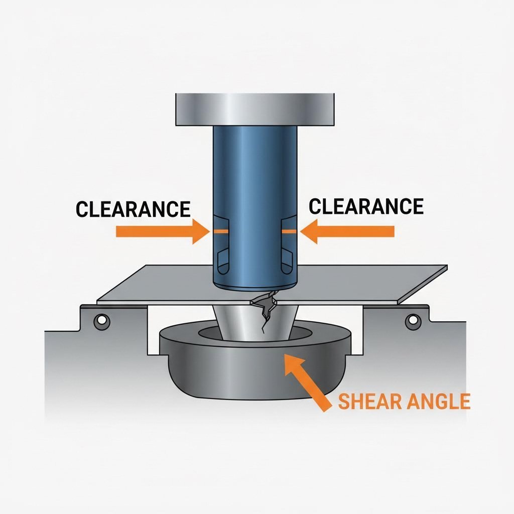
The tensile strength and shear strength of the raw material are the primary drivers for tonnage and tool wear. For instance, stamping HSLA steel requires significantly higher tonnage and tighter clearances compared to mild steel. Conversely, aluminum alloys, while softer, are prone to galling and require polished active tool components or specialized coatings like TiCN (Titanium Carbonitride).
| Material Type | Shear Strength (Approx.) | Key Design Challenge | Clearance Rule of Thumb |
|---|---|---|---|
| Mild Steel (CRS) | 35,000 PSI | Burr control | 10-12% of Thickness |
| HSLA Steel | 60,000+ PSI | Springback & Punch Wear | 12-15% of Thickness |
| Aluminum (6061) | 25,000 PSI | Galling & Slug Pulling | 8-10% of Thickness |
| Stainless (304) | 80,000+ PSI | Work Hardening | 15-18% of Thickness |
Addressing Springback Early
One of the most persistent defects in automotive bracket stamping is springback—the tendency of metal to partially return to its original shape after bending. This is particularly acute in HSLA materials. To counteract this, designers must engineer "over-bend" stations or apply rotary bending techniques rather than standard wipe bending. For 90-degree brackets, designing the die to over-bend by 2-3 degrees is a common practice to achieve the final print tolerance.
Phase 2: Strip Layout Optimization
The strip layout is the blueprint of the progressive die. It determines the cost-efficiency of the entire production run. A poorly designed layout wastes material and destabilizes the die, while an optimized layout can save thousands of dollars in scrap annually.
Bridge Thickness and Carrier Design
The "bridge" or "web" is the material left between parts to carry them through the die. Minimizing this width reduces scrap, but making it too thin risks strip buckling. A standard engineering rule for steel brackets is to set the bridge width between 1.25 × Thickness (t) and 1.5 × Thickness (t). For high-speed applications or thinner materials, this may need to be increased to 2t to prevent feeding issues.
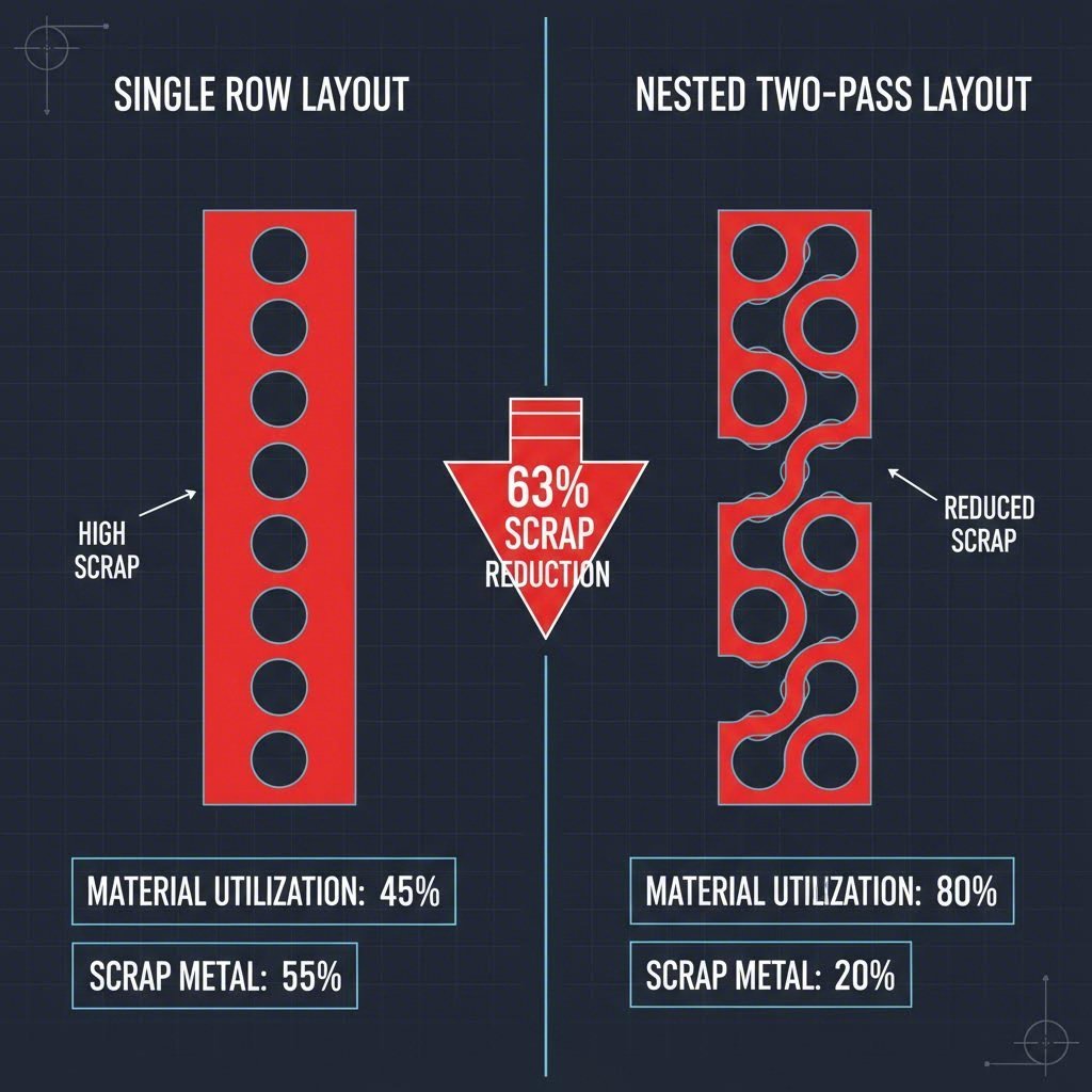
Calculating Material Utilization
Efficiency is measured by Material Utilization (%). The goal for automotive brackets should be >75%. The formula to validate your nesting strategy is:
Utilization % = (Area of Finished Blank) / (Pitch × Strip Width) × 100
If the result is below 65%, consider a "two-pass" or "interlocked" nesting layout where two brackets are stamped facing each other to share a common carrier line. This approach is highly effective for L-shaped or U-shaped brackets.
Pilot Pin Positioning
Precision relies on accurate strip positioning. Pilot holes should be punched in the very first station. The pilot pins in subsequent stations align the strip before the die closes completely. For brackets with tight hole-to-hole tolerances, verify that the pilots engage the strip at least 6mm before the form punches contact the material.
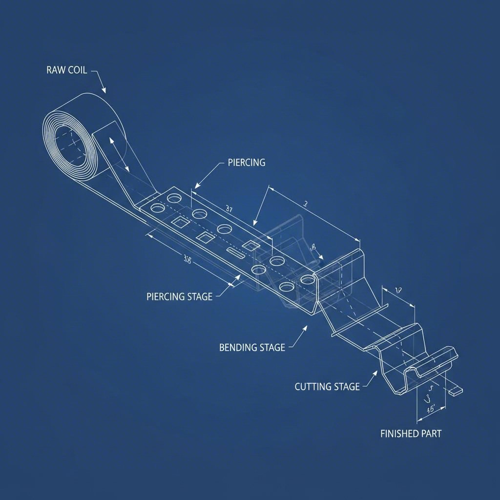
Phase 3: Station Sequencing & Tonnage
Determining the correct sequence of operations—pierce, pilot, trim, form, and cut-off—prevents die failures. A logical progression ensures the strip remains stable throughout the process. Ideally, piercing happens early to establish pilot holes, while heavy forming is distributed to balance the load.
Calculating Required Tonnage
Engineers must calculate the total force required to ensure the press has sufficient capacity (and energy) to perform the work. The formula for blanking and piercing tonnage is:
Tonnage (T) = Length of Cut (L) × Material Thickness (t) × Shear Strength (S)
According to industry calculation standards, you must also account for stripping force (typically 10-20% of cutting force) and the pressure of nitrogen springs or cushions used for holding the strip. Failure to include these auxiliary loads can result in under-sizing the press, leading to stalling at the bottom dead center.
Center of Loading
A critical but often overlooked calculation is the "Center of Loading." If the cutting and forming forces are concentrated on one side of the die, it creates an off-center load that tips the ram, causing premature wear on press gibs and die pillars. Balance the layout by distributing high-tonnage stations (like cutting large perimeters) symmetrically around the die's centerline.
Phase 4: Solving Common Bracket Defects
Even with a robust design, defects can occur during trialout. Debugging requires a systematic approach to root cause analysis.
- Burrs: Excessive burrs usually indicate incorrect clearance or dull tooling. If burrs appear on only one side of the hole, the punch is likely misaligned. Verify the clearance is uniform around the entire perimeter.
- Slug Pulling: This occurs when the scrap slug sticks to the punch face and is pulled out of the die button. It can damage the strip or the die in the next stroke. Solutions include using "slug-hugger" dies with retention grooves or adding a spring-loaded ejector pin to the punch center.
- Misalignment (Camber): If the strip curves (cambers) as it feeds, the carrier may be distorting. This often happens if the release of the strip during forming is restricted. Ensure that pilot lifters allow the material to float freely during the feed cycle to relieve stress.
Phase 5: Cost Drivers & Supplier Selection
The transition from design to production involves commercial decisions that impact the final part cost. The complexity of the die—driven by the number of stations and the necessary tolerance—is the biggest capital expense. For low-volume brackets (<20,000/year), a single-stage or compound die may be more economical than a progressive die.
However, for high-volume automotive programs, the efficiency of a progressive die justifies the initial investment. When selecting a manufacturing partner, verify their ability to handle the specific tonnage and bed size requirements of your die. For example, Shaoyi Metal Technology’s comprehensive stamping solutions bridge the gap from prototyping to mass production, offering IATF 16949-certified precision for critical components like control arms and subframes. Their capability to handle press loads up to 600 tons ensures that even complex, heavy-gauge brackets can be produced consistently.
Finally, always require a detailed Design for Manufacturing (DFM) review before cutting steel. A competent supplier will simulate the forming process (using software like AutoForm) to predict thinning and splitting risks, allowing for virtual corrections that save weeks of physical rework.
Mastering Progressive Die Efficiency
Designing progressive dies for automotive brackets is an exercise in balancing precision, material efficiency, and tool longevity. By rigorously applying engineering fundamentals—from precise bridge calculations and tonnage formulas to strategic material selection—engineers can create tooling that delivers millions of defect-free parts. The key is to treat the strip layout as the foundation; if the layout is optimized, the die will run smoothly, defects will be minimized, and profitability will be maximized.
Frequently Asked Questions
1. What is the minimum bridge thickness for progressive dies?
The standard minimum bridge thickness (or web width) is typically 1.25 to 1.5 times the material thickness (t). For example, if the bracket material is 2mm thick, the bridge should be at least 2.5mm to 3mm. Going below this limit increases the risk of the strip buckling or breaking during the feed cycle, especially in high-speed operations.
2. How do you calculate tonnage for progressive stamping?
Total tonnage is calculated by summing the force required for all operations (cutting, bending, forming) plus the force of the strippers and pressure pads. The base formula for cutting force is Perimeter × Thickness × Shear Strength. Most engineers add a safety margin of 20% to the total calculated load to account for tool dulling and press variation.
3. How can I reduce scrap in progressive die design?
Scrap reduction starts with the strip layout. Techniques include nesting parts (interlocking shapes to use the same carrier web), reducing the bridge width to the safe minimum, and using a "two-pass" layout for L-shaped or triangular brackets. Improving material utilization to above 75% is a key target for cost-efficient automotive stamping.