 Small batches, high standards. Our rapid prototyping service makes validation faster and easier —

Plate Fabrication Secrets: Cut Costs Without Cutting Corners

What Plate Fabrication Really Means in Industrial Manufacturing
When you hear the term "plate fabrication," what comes to mind? If you're picturing thin metal sheet being bent into enclosures or appliances, you're actually thinking of something quite different. Plate fabrication is a specialized branch of metal fabrication that deals exclusively with thicker, heavier materials—and it demands an entirely different approach to equipment, techniques, and expertise.
Defining Plate vs Sheet Metal Work
The distinction between plate and metal sheet often confuses newcomers to the industry. Here's the key difference: steel plate refers to thicker material, typically 3/16 inch (approximately 5mm) and above, that's produced as individual flat pieces through a rolling process. According to Langley Alloys, plate thickness can reach up to 150mm or more from certain producers.
Metal sheet, on the other hand, is thinner material cut from continuously rolled coils. While sheet metal is commonly used for appliances, enclosures, and lighter applications, steel plate serves heavy-duty purposes in machines, structural sections, and large-scale fabrications where strength and durability are non-negotiable.
Why does this matter? Because working with thicker materials requires fundamentally different machinery. You can't simply scale up sheet metal equipment—plate work demands specialized press brakes with higher tonnage, heavy-duty cutting systems, and welding procedures designed for multi-pass applications on thick sections.
Core Operations in Plate Processing
Steel fabrication involving plate materials encompasses four primary operations that transform raw steel plate into finished components:
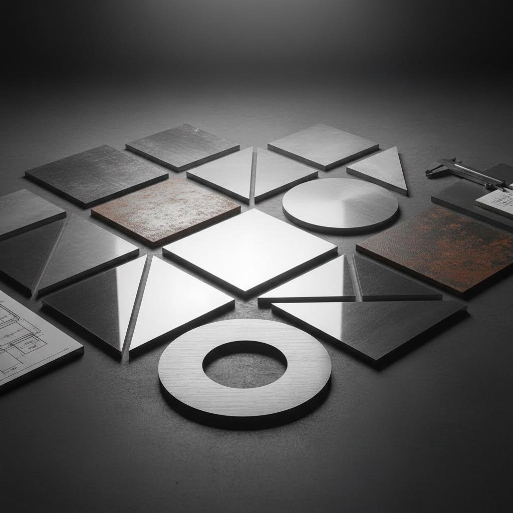
- Cutting: Precision separation using plasma, laser, waterjet, or oxy-fuel methods based on thickness and accuracy requirements
- Forming: Shaping plates through press brake bending, rolling, or specialized forming equipment capable of handling heavy materials
- Welding: Joining plate sections using techniques suited to thicker materials, often requiring preheating and multi-pass strategies
- Finishing: Surface preparation, coating, and final treatments to meet application specifications
Each operation presents unique challenges when working with plate versus sheet. For example, welding thicker materials often requires Complete Joint Penetration (CJP) welds with multiple passes, along with higher preheat and temperature maintenance requirements.
Structural steel & plate fabrication plays a critical role across numerous sectors that depend on the strength and durability only heavy plate can provide:
- Construction: Buildings, warehouses, bridges, and railway stations
- Pressure Vessels: Tanks and containers designed to withstand internal pressure
- Heavy Equipment: Large-scale agricultural and industrial machinery
- Marine and Shipbuilding: Hull components and structural elements
- Military and Defense: Armored vehicles and protective equipment
- Energy Sector: Storage tanks and processing equipment
Understanding these fundamentals sets the stage for making smarter decisions about your fabrication projects—whether you're selecting materials, choosing cutting methods, or evaluating potential fabrication partners.
Cutting Methods That Shape Modern Plate Work
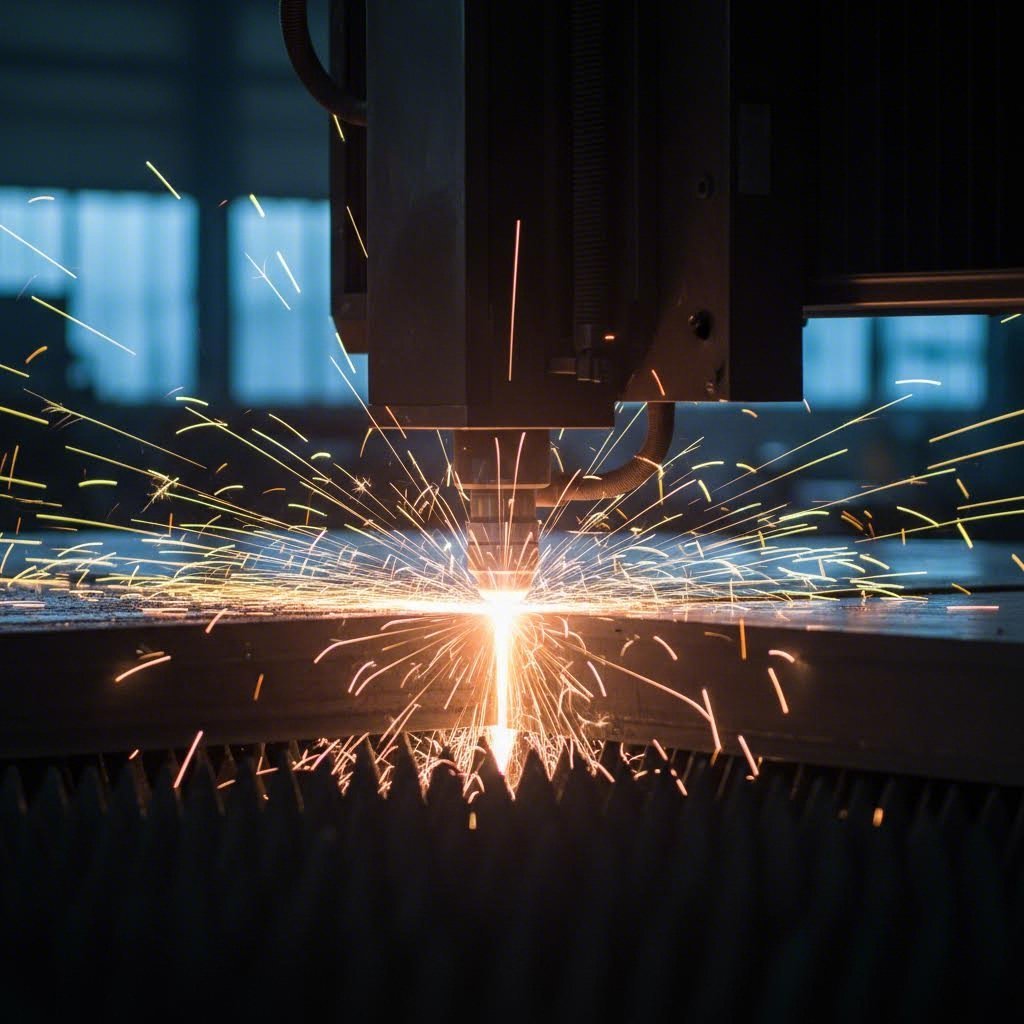
Imagine you're standing in front of a 2-inch thick steel plate that needs precise cuts for a pressure vessel project. Which metal cutter do you reach for? The answer isn't as straightforward as you might think—because in plate fabrication, your cutting method directly impacts everything from edge quality to welding preparation to final project costs.
Four primary cutting technologies dominate modern plate work, each with distinct advantages that make them ideal for specific applications. Understanding these differences helps you select the right approach and avoid costly mistakes downstream.
Plasma Cutting for Speed and Versatility
CNC plasma cutting uses an accelerated jet of hot plasma—reaching temperatures up to 45,000°F (25,000°C)—to cut through electrically conductive materials. According to StarLab CNC, modern plasma tables can cut 1/2-inch mild steel at speeds exceeding 100 inches per minute, making it the fastest option for medium to thick plates.
What makes plasma cutting particularly valuable for plate fabrication? It handles an impressive thickness range from 0.018 inches up to 2 inches with optimal performance, and high-definition plasma systems now rival laser quality on many applications. The technology excels in structural steel work, heavy equipment manufacturing, and shipbuilding—anywhere you need to process thick plates quickly and economically.
Modern CNC plasma tables also offer versatile bevel cutting capabilities for weld preparation, which reduces secondary operations and speeds up overall project timelines.
Laser Cutting for Precision Work
When precision trumps speed, laser cutting delivers exceptional results. Fiber lasers employ a focused beam of concentrated energy to melt, burn, or vaporize material with minimal heat-affected zones. This translates to extremely precise cuts—typically achieving tolerances of ±0.05-0.1 mm according to Okdor's fabrication data.
Here's the trade-off you'll notice: laser cutter performance shines on thin to medium materials but decreases significantly as thickness increases. Laser cutting maintains effective precision up to approximately 25mm, after which heat accumulation causes tolerance drift and degraded edge quality. For plate work specifically, consider laser cutting when you need intricate designs or tight tolerances on plates under 1 inch thick.
The kerf width—the amount of material removed during cutting—is narrowest with laser cutting, which maximizes material utilization and reduces waste on precision parts.
Waterjet Cutting for Heat-Sensitive Materials
What if your application absolutely cannot tolerate heat distortion? Waterjet cutting eliminates thermal concerns entirely. Operating at pressures up to 90,000 PSI, waterjet systems use a high-pressure stream of water mixed with abrasive particles to cut virtually any material without generating heat.
This cold-cutting process preserves material properties and structural integrity—critical for heat-treated alloys, titanium aerospace components, or any application where material microstructure matters. Waterjet maintains consistent ±0.03-0.08 mm tolerances across all thickness ranges, even cutting plates up to 200mm while holding precision specifications.
The versatility extends beyond metals. Interestingly, the same fundamental waterjet technology applies when considering how to cut plexiglass or how do you cut perspex—materials that would melt or warp under thermal cutting methods. Waterjet handles these heat-sensitive materials without distortion, making it the go-to solution for diverse fabrication needs.
Oxy-Fuel Cutting for Heavy Plate
For the thickest plate materials, oxy-fuel cutting remains a workhorse technology. According to Xometry, oxygen fuel cutting can handle steel plates up to 12 inches thick—far beyond the practical limits of other methods—and cuts 2-inch thick steel approximately three times faster than plasma.
The process works by heating steel to its ignition temperature (700-900°C), then blasting high-pressure oxygen onto the surface to create a chemical reaction that forms iron oxide. This molten slag is blown away by the oxygen flow, leaving the cut path.
Oxy-fuel cutting is limited to mild and low-alloy steels with carbon content between 0.04-0.3%, but for these materials, nothing matches its speed on thick sections. Metal fabrication shops, construction sites, and nautical applications rely on its portability and ability to cut steel without electricity.
Comparing Cutting Technologies at a Glance
| Parameter | Plasma Cutting | Laser Cutting | Waterjet Cutting | Oxy-Fuel Cutting |
|---|---|---|---|---|
| Maximum Thickness | Up to 2 inches optimal | Up to 25mm (1 inch) | Up to 200mm (8 inches) | Up to 12 inches |
| Precision Tolerances | ±0.5-1.5 mm | ±0.05-0.1 mm | ±0.03-0.08 mm | ±1.5-3.0 mm |
| Edge Quality | Good (high-def: near-laser) | Excellent | Good to Excellent | Rough (requires finishing) |
| Heat-Affected Zone | Moderate | Minimal on thin material | None (cold cutting) | Significant |
| Cutting Speed | Fast | Fast (thin material) | Slow | Fast (thick plate) |
| Ideal Applications | Structural steel, heavy equipment | Precision parts, intricate designs | Heat-sensitive materials, titanium | Thick mild steel, construction |
How Cutting Selection Affects Downstream Operations
Your cutting method choice ripples through every subsequent fabrication step. The kerf width determines how much material disappears during cutting—laser cutting produces the narrowest kerf for optimal material utilization, while oxy-fuel creates wider cuts that waste more material but may be acceptable for structural applications.
Edge quality directly impacts welding preparation. Plasma and laser cuts often require minimal preparation before welding, while oxy-fuel cuts typically need grinding to remove slag and clean the edge. When specifying weld joints on thick plate assemblies, factor in whether your cutting method produces weld-ready edges or requires secondary operations.
Heat-affected zones present another consideration. Thermal cutting methods can alter material properties near the cut edge, potentially affecting weld quality or mechanical performance in critical applications. For demanding environments where material integrity cannot be compromised, waterjet's cold-cutting process eliminates this concern entirely.
With cutting methods established, the next challenge in plate fabrication involves forming and bending these thick materials—processes that require entirely different equipment and techniques than sheet metal work.
Forming and Bending Thick Plate Materials
You've selected your cutting method and prepared your metal plate blanks—now comes the challenge that separates plate fabrication from standard sheet metal fabrication. Bending steel plates measuring 3/16 inch or thicker isn't simply a matter of applying more force. It requires understanding the physics of material deformation, specialized equipment, and techniques that prevent costly defects.
Why does thickness matter so much? According to Chicago Metal Rolled Products, when you bend thick plate, the material simultaneously expands on the outside surface while compressing on the inside. This creates internal stresses that behave very differently than in thin sheet metal—and managing these stresses determines whether you end up with precision components or scrap.
Press Brake Operations for Heavy Plate
Press brake bending remains the workhorse for forming thick steel plates into angled shapes. The process uses two tools: an upper punch and a lower V-shaped die. Positioning the plate over the die, the punch descends and forces the material to conform to the desired angle.
Two primary methods apply here:
- Air Bending: The punch doesn't push the material all the way to the die bottom, leaving space underneath. This provides flexibility but produces more springback.
- Bottoming: The punch forces material completely into the die cavity. This method offers better angle control due to reduced springback—critical when working with heavy plate.
Here's what you'll notice with thicker materials: the required tonnage increases exponentially, and minimum bend radii become significantly larger. A gauge size chart might show thin sheet bending to tight radii, but once you move beyond standard gauge sizes into true plate territory, the rules change dramatically.
An experienced operator calculates expected springback based on material properties, thickness, and bend angle. This knowledge speeds production by reducing trial-and-error attempts—each adjustment on heavy plate consumes time and risks damaging expensive material.
Roll Forming and Plate Rolling Techniques
When your project requires curved profiles rather than angular bends, plate rolling becomes essential. This process applies continuous force through three or four rollers to gradually form cylindrical or conical shapes—think pressure vessel shells, storage tank sections, or large structural tubes.
Plate rolling introduces additional complexity compared to press brake work. The material passes through multiple roller stations, each incrementally shaping the curve. Grain direction becomes particularly important here: rolling parallel versus perpendicular to the grain affects both the achievable radius and the likelihood of surface cracking.
For calculating minimum bend radii, research by Datsko and Yang established that the reduction in area (a tensile test property) serves as the primary predictor. Their formula suggests that high-strength steels like ASTM A514 with 40% reduction in area can achieve a bend radius as tight as half the plate thickness. However, most fabricators apply generous safety factors to these theoretical minimums—defensive design protects against material variations that could cause failures.
Common Forming Defects and Prevention Strategies
Heavy plate forming presents unique challenges that don't occur with lighter materials. Understanding these defects—and how to prevent them—saves significant time and material costs.
- Cracking: Longitudinal cracks along bend lines result from exceeding the material's ductility limits. Prevention involves using the largest practical bend radii, selecting more ductile alloys, and spreading deformation across multiple forming passes.
- Springback: Metal's tendency to partially return toward its original shape after forming. Compensation requires overbending to a calculated degree based on material properties and thickness. Inconsistent springback often stems from variations in material hardness or thickness.
- Wrinkling: Compressive forces on the inside of bends can cause material buckling on thinner sections. Proper die design and adequate support during forming minimize this issue.
- Dimensional Inaccuracy: Variations in angle, radius, or overall dimensions. Prevention requires consistent material properties, proper equipment calibration, and roller parallelism checks.
- End Flare: Roll formed products that open up at cut ends due to residual stresses. MMC Roll Form recommends purchasing high-quality strip with controlled residual stresses and optimizing roller design to minimize stress accumulation.
Distortion Control Methods
Working thick materials under high forming forces generates significant internal stresses that can cause distortion—sometimes immediately, sometimes hours or days after forming. Controlling this distortion requires attention to multiple factors:
Material selection matters first. High-quality plate with uniform thickness and controlled residual stresses from the mill behaves more predictably during forming. A wedge profile in the input material creates uneven stresses that manifest as warping or oil canning in finished parts.
Forming sequence also affects outcomes. Strategic planning of bend order—forming inner bends before outer ones, or working from the center outward—can minimize cumulative stress buildup that leads to distortion.
Finally, post-forming stress relief may be necessary for critical applications. Heat treatment after forming allows internal stresses to redistribute, stabilizing dimensions before final machining or assembly.
With forming and bending fundamentals covered, the next critical decision in your plate fabrication project involves selecting the right material—a choice that affects not just performance but also how easily that material will form, weld, and ultimately meet your application requirements.
Selecting the Right Plate Material for Your Application
Picture this scenario: you're specifying materials for a heavy equipment component that will face constant abrasion, occasional impact, and outdoor exposure. Do you reach for economical A36 carbon steel, invest in hardened AR500 plate, or consider stainless steel sheet metal for corrosion protection? The answer depends on understanding how each material's properties align with your specific application requirements—and how those choices ripple through your entire fabrication budget.
Material selection in plate fabrication isn't just about picking the strongest option. It's about balancing mechanical performance, corrosion resistance, fabrication complexity, and cost to find the sweet spot for your project. Let's break down the most common choices and when each makes sense.
Carbon Steel Grades and Their Applications
Carbon steel dominates plate fabrication due to its versatility, availability, and cost-effectiveness. Two grades appear in most discussions: A36 structural steel and AR500 abrasion-resistant plate. Understanding their fundamental differences helps you avoid costly over-specification—or dangerous under-specification.
A36 Steel serves as the workhorse of structural applications. According to Redstone Manufacturing, A36 undergoes a hot-rolling process that contributes to its low cost, excellent workability, and notable impact resistance. With a tensile strength of 58,000-80,000 PSI and yield strength around 36,000 PSI, it handles most structural loads while remaining easy to cut, drill, and weld.
Where does A36 shine? Buildings, bridges, shipbuilding, and automotive parts—anywhere you need reliable strength without specialized performance requirements. Its excellent weldability means faster fabrication times and lower labor costs. The trade-off? A36 offers reduced corrosion resistance and requires protective coatings in harsh environments.
AR500 Steel takes a completely different approach. Manufactured through quenching and tempering processes, AR500 achieves exceptional hardness (approximately 500 Brinell) and abrasion resistance. This makes it ideal for mining equipment, shooting targets, armored vehicles, and any application demanding resistance to wear and impact.
Here's the critical consideration: AR500's superior hardness comes with trade-offs. It costs significantly more than A36, requires specialized machinery and experienced operators for machining, and its hardness can lead to brittleness under certain impact conditions. However, in high-wear applications, AR500's extended lifespan often offsets the higher initial investment.
Stainless Steel Plate Selection
When corrosion resistance becomes non-negotiable, stainless steel sheet metal enters the conversation. The 300-series austenitic grades dominate plate fabrication, with 304 and 316 stainless steel representing the most common choices.
304 Stainless Steel offers excellent corrosion resistance for general applications at a lower cost than more specialized grades. It works well in food processing, architectural applications, and chemical handling where aggressive chloride exposure isn't a concern.
316 Stainless Steel steps up protection with added molybdenum content, providing superior resistance to chlorides and marine environments. This grade becomes essential for coastal installations, pharmaceutical equipment, and chemical processing where pitting corrosion would compromise 304 stainless.
The fabrication complexity increases with stainless steel. Both grades require careful heat management during welding to prevent sensitization—a condition where chromium carbides form at grain boundaries and reduce corrosion resistance. Proper filler metal selection, interpass temperature control, and sometimes post-weld treatments add steps to the fabrication process.
Specialty Alloys for Demanding Environments
Some applications push beyond what carbon or stainless steels can deliver. Aluminum sheet metal offers an excellent strength-to-weight ratio for transportation, aerospace, and marine applications where weight savings justify higher material costs. Aluminum sheet fabrication requires different techniques than steel—lower welding temperatures, specialized filler metals, and attention to oxide layer management.
High-strength low-alloy (HSLA) steels like A572 provide improved strength over A36 while maintaining reasonable weldability. These grades see heavy use in structural applications where code requirements or weight constraints demand higher performance without the jump to specialty alloys.
For extreme temperature or corrosive environments, nickel alloys, duplex stainless steels, and titanium enter consideration—though these typically require specialized fabrication expertise and significantly higher budgets.
Comparing Material Properties at a Glance
| Material | Tensile Strength (PSI) | Weldability | Corrosion Resistance | Typical Applications | Relative Cost |
|---|---|---|---|---|---|
| A36 Carbon Steel | 58,000-80,000 | Excellent | Low (requires coating) | Structural steel, bridges, buildings | $ |
| AR500 Abrasion-Resistant | 230,000+ | Moderate (requires preheat) | Low-Moderate | Mining equipment, armor, wear plates | $$$ |
| 304 Stainless Steel | 73,000-90,000 | Good (heat control needed) | High | Food processing, architectural | $$ |
| 316 Stainless Steel | 75,000-95,000 | Good (heat control needed) | Very High (chloride resistant) | Marine, pharmaceutical, chemical | $$$ |
| Aluminum (6061-T6) | 42,000-45,000 | Good (specialized techniques) | High (natural oxide layer) | Transportation, aerospace, marine | $$ |
How Material Grade Affects Fabrication Complexity
Your material choice doesn't just affect raw material costs—it cascades through every fabrication operation. According to CSM Fabrication, processing costs from cutting, bending, welding, and finishing often rival or exceed material costs, making fabrication complexity a critical budget consideration.
Consider the differences in cutting alone. A36 steel cuts easily with any thermal method—plasma, laser, or oxy-fuel all work efficiently. AR500's hardness slows cutting speeds and accelerates consumable wear, increasing per-part processing costs. Stainless steels require attention to heat-affected zones to preserve corrosion resistance, while aluminum sheet demands different parameters entirely to prevent melting and dross formation.
Welding complexity follows similar patterns. A36 welds readily with minimal preparation. AR500 typically requires preheat to prevent hydrogen cracking in the heat-affected zone—adding time and equipment to every weld joint. Stainless steel sheet metal demands controlled interpass temperatures and sometimes back-purging with inert gas to prevent oxidation and maintain corrosion resistance.
Thickness availability also varies by material grade. Carbon steel plates commonly range from 3/16 inch to several inches thick with ready availability. Specialty alloys may require longer lead times or minimum order quantities that affect project scheduling and inventory costs.
Balancing Performance Against Total Project Cost
Smart material selection considers total project cost—not just the price per pound of raw material. Here's a practical framework for decision-making:
- Define performance requirements first: What mechanical loads, corrosion exposure, temperature extremes, or wear conditions will the finished product face?
- Identify the minimum grade that meets requirements: Over-specifying materials wastes money; under-specifying creates failure risks.
- Factor in fabrication complexity: A cheaper material that requires specialized welding, heat treatment, or finishing may cost more than a premium grade that fabricates easily.
- Consider lifecycle costs: AR500's higher upfront cost may deliver lower total cost in high-wear applications where A36 would require frequent replacement.
- Evaluate availability and lead times: Standard grades ship quickly; specialty alloys may add weeks to project schedules.
The relationship between material selection and fabrication success extends beyond just choosing the right grade. Once you've specified your material, the welding techniques used to join those plates become equally critical—particularly when working with thick sections that demand specialized joint preparation and process parameters.
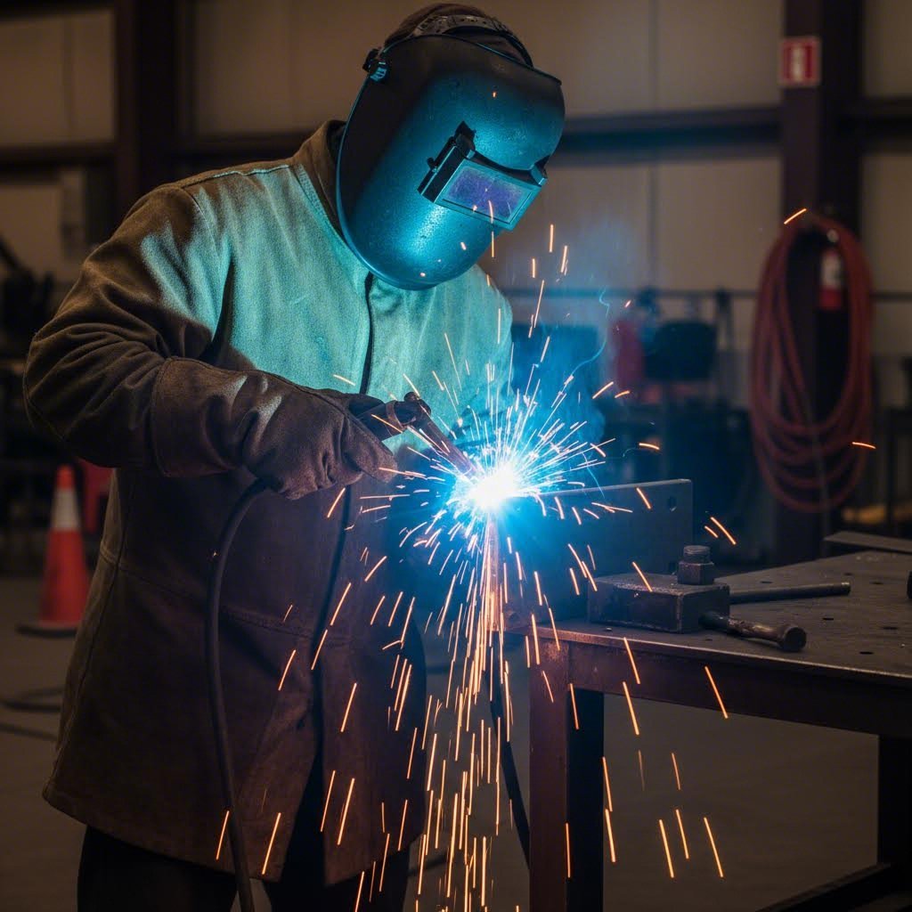
Welding Techniques for Heavy Plate Assemblies
You've selected your material, cut your blanks, and formed your components—now comes the operation that literally holds everything together. Welding thick plate isn't simply a matter of turning up the amperage on your standard equipment. It demands different joint designs, specialized preparation, and process parameters that account for the unique challenges of fusing heavy sections without introducing defects or distortion.
When comparing MIG vs TIG welding for plate applications, or deciding between multi-pass strategies, your choices directly impact weld quality, production speed, and total project costs. Understanding these considerations helps you avoid costly rework and ensure your welded steel assemblies meet specification requirements.
MIG vs TIG for Plate Welding Applications
The eternal debate of tig vs mig welding takes on particular significance when working with thick plate materials. Each process offers distinct advantages depending on your application requirements, material type, and production volume.
MIG (GMAW) Welding dominates high-production plate fabrication for good reason. It deposits filler metal quickly, maintains consistent penetration on long runs, and requires less operator skill than TIG for acceptable results. On carbon steel plates, MIG welding with appropriate wire diameter and shielding gas mixtures produces sound welds at production speeds that keep projects on schedule.
For welded steel pipe and structural assemblies, MIG's high deposition rates translate directly to lower labor costs per joint. When welding thick plate sections requiring multiple passes, MIG allows operators to fill joints efficiently while maintaining adequate fusion between layers.
TIG (GTAW) Welding earns its place when precision and control matter more than speed. Aluminum welding on heavy plate almost always favors TIG due to its superior heat control and cleaner results on this heat-sensitive material. Similarly, critical welded pipes in pressure service often specify TIG root passes for their superior penetration control and defect-free results.
The practical reality? Many plate fabrication shops use both processes strategically—TIG for root passes requiring precise penetration, then switching to MIG or flux-cored processes for fill and cap passes that complete the joint efficiently.
Weld Preparation and Joint Design
Here's where plate fabrication diverges dramatically from sheet metal work: joint preparation becomes critical rather than optional. According to Chicago Metal Rolled Products, the weld prep allows filler metal a crevice to penetrate into the base metal being welded—and any weld that lacks penetration is "somewhat like sticking bubble gum on the joint."
Four primary bevel configurations apply to plate and cylinder work:
- Y-Bevel: A beveled edge with a land (flat portion at the root)
- V-Bevel: A bevel extending to a knife edge with no land
- X-Bevel (Double-V): Both sides of the seam beveled from both faces
- K-Bevel: One side double-beveled, the opposite side square
Edge quality matters as much as geometry. The cut edge must be clean and free of oxides that could compromise the welding process. Thermal cutting methods like plasma leave heat-affected zones that can make edges harder than the base material, while oxy-fuel cutting often produces slag that requires grinding before welding.
For heavy plate over 3/8 inch thick, beveling equipment choices significantly impact quality and cost. Portable milling head bevelers produce machined-quality edges with carbide cutting inserts. Plasma cutting systems with automated track-and-buggy setups deliver high-quality beveled edges on carbon, stainless, and aluminum in thicknesses over 2 inches. Rotary mill head double bevelers mount to 3D trolleys that "float" to adjust for uneven surfaces, allowing precise control of bevel angle and material removal.
How Plate Thickness Influences Welding Parameters
Thick plate demands adjustments across every welding variable. Preheat requirements increase with thickness and carbon equivalent—preventing hydrogen cracking in the heat-affected zone becomes essential on heavy sections. Multi-pass strategies replace single-pass approaches, with each layer requiring controlled interpass temperatures to maintain metallurgical integrity.
Travel speed, wire feed rate, and voltage settings all require recalibration for thick material. Welding parameters that produce beautiful beads on 1/4-inch plate may result in lack of fusion or excessive spatter on 1-inch sections. The heat input calculation—considering amperage, voltage, and travel speed—becomes a critical specification rather than an afterthought.
Common Welding Defects in Thick Plate Work
Heavy plate welding introduces defect modes that rarely appear in thinner materials. Understanding their causes helps prevent costly repairs and inspection failures:
- Lack of Fusion: Insufficient heat input or improper technique prevents complete bonding between weld metal and base material or between passes. Common when travel speed is too fast or amperage too low for the joint configuration.
- Hydrogen Cracking: Also called cold cracking, this occurs hours or days after welding when hydrogen trapped in the weld migrates and causes brittle fracture. Prevention requires proper preheat, low-hydrogen consumables, and controlled cooling.
- Incomplete Penetration: The weld fails to reach the root of the joint, leaving unfused material that creates stress concentrations. Proper bevel design and root gap control prevent this defect.
- Porosity: Gas pockets trapped in the solidifying weld metal from contamination, insufficient shielding, or improper technique. Surface cleanliness and adequate gas coverage prevent most porosity issues.
- Slag Inclusions: Non-metallic material trapped between weld passes when slag isn't completely removed. Thorough interpass cleaning eliminates this defect.
- Undercut: Grooves melted into the base metal adjacent to the weld toe that aren't filled by weld metal. Excessive amperage or improper torch angle commonly cause undercut.
Distortion Control During Welding
Welding distortion represents one of the most persistent challenges in plate fabrication. According to Xiris, distortion is a permanent change in shape caused by uneven thermal expansion and contraction—the heated zone wants to grow, surrounding material restrains it, and the cooled weld zone then wants to shrink while the rest holds position.
The type of distortion depends on section thickness, joint symmetry, and bead placement. Thin stock with long beads favors bowing and buckling. Asymmetric joints favor angular changes. Multi-pass welds can stack small movements into larger deformations that become impossible to correct.
Effective distortion control strategies include:
- Balanced Welding Sequences: Alternating sides, staggering welds, and breaking long seams into shorter segments spreads heat more evenly and cancels contraction forces.
- Proper Fixturing: Clamps, strongbacks, and jigs hold parts in position during welding. Presetting joints with small counter-angles can compensate for expected pulls.
- Heat Input Control: Using smaller beads, steady travel, and stable arc length keeps heat contained. Oversized beads and slow travel expand the heat-affected zone and increase shrinkage.
- Symmetrical Joint Design: Double fillets and balanced bevels help avoid strong directional pulls that cause angular distortion.
Post-Weld Treatments and Inspection Requirements
Critical welded assemblies rarely go directly from the welding station to service. Post-weld stress relief heat treatment allows internal stresses to redistribute, stabilizing dimensions and reducing the risk of service failures. This becomes particularly important for thick sections where high residual stresses concentrate near weld toes and could initiate fatigue cracks under cyclic loading.
Inspection requirements scale with application criticality. Visual inspection catches surface defects, but thick plate welds often require non-destructive testing (NDT) methods to verify internal integrity. Radiographic testing (RT) reveals volumetric defects like porosity and slag inclusions. Ultrasonic testing (UT) detects lack of fusion and cracking. Magnetic particle inspection (MT) and dye penetrant testing (PT) identify surface-breaking defects invisible to the naked eye.
For pressure vessel work and structural applications governed by codes, inspection documentation becomes part of the permanent quality record—tracing each weld back to specific welders, procedures, and test results.
With welding fundamentals established, the next consideration moves upstream in the project timeline—how design decisions made before fabrication begins can dramatically affect both weld quality and overall project costs.
Design Principles That Reduce Fabrication Costs
Imagine submitting your plate fabrication drawings for a quote—only to receive pricing that blows your budget or, worse, a no-quote response. What went wrong? In many cases, the issue isn't the fabricator's capabilities but design choices made weeks earlier that created unnecessary manufacturing complexity.
Design for Manufacturability (DFM) bridges the gap between what looks good on screen and what fabricates efficiently in the real world. When engineers understand how their decisions impact metal fab operations, they unlock significant cost savings without compromising functionality. Let's explore the principles that separate budget-friendly designs from expensive headaches.
Designing for Efficient Cutting and Nesting
Every plate fabrication project starts with raw material, and how efficiently you use that material directly impacts your bottom line. According to Putsch USA, nesting optimization—arranging parts on raw panels for maximum utilization—delivers material cost savings, improved efficiency, and reduced machine wear.
Here's what smart designers consider before finalizing their drawings:
- Standard sheet sizes: Most fabricators work with 48" x 120" or 60" x 120" sheets. Designing parts that nest efficiently within these dimensions minimizes waste and reduces per-part costs.
- Edge buffers: Leave approximately 0.125" between nested parts and from sheet edges. Ignoring this requirement forces fabricators to adjust layouts, potentially wasting material.
- Consistent material thickness: Grouping parts with the same thickness enables dynamic nesting across multiple orders, improving overall shop efficiency.
- Part orientation flexibility: Allowing rotational or mirror nesting—when grain direction doesn't matter—can significantly improve material utilization.
Material utilization percentages translate directly to your invoice. A design achieving 85% utilization versus one struggling at 65% means paying for scrap that ends up in the recycling bin rather than your finished product.
Tolerance Specifications That Balance Cost and Function
Tight tolerances sound impressive on drawings, but they often create expensive problems in fabrication. Every dimension you specify requires measurement during inspection—and overly aggressive tolerances demand additional operations, specialized equipment, or excessive quality control time.
Consider this practical framework for tolerance specification:
- Identify truly critical dimensions: Use geometric dimensioning and tolerancing (GD&T) symbols or bubbles to highlight the measurements that actually matter for fit and function.
- Apply standard fabrication tolerances elsewhere: Most plate fabrication operations achieve ±1/16" on linear dimensions and ±1° on bends without special effort. Specifying tighter tolerances than necessary adds cost without adding value.
- Understand stack-up effects: According to MetalsCut4U, tolerancing issues and stack-up errors rank among the most common fabrication mistakes. When multiple parts assemble together, individual tolerances accumulate—a concept many designers overlook until assembly fails.
When referencing a sheet metal gauge chart for material specifications, remember that 14 gauge steel thickness measures approximately 0.0747 inches—but the actual delivered thickness varies within industry-standard tolerances. Designing for these real-world variations prevents assembly problems later.
Assembly Considerations in Design
The decisions you make on individual parts cascade into assembly operations. Smart design anticipates how components will fit together and provides features that simplify—rather than complicate—the fabrication process.
Weld preparation starts at the design stage. Specifying joint configurations that match your fabricator's capabilities prevents costly surprises. Tab-and-slot features orient parts automatically during welding, reducing fixture complexity and ensuring consistent alignment. According to All Metals Fabricating, this approach "reduces setup time and ensures parts fit together correctly."
Hardware selection matters more than many engineers realize. Standardizing fastener sizes—particularly using 10-32 hardware—simplifies assembly and inventory management. When specifying press-in hardware, ensure non-hardware holes use different diameters to prevent installation errors.
Symmetry creates hidden risks. Parts that appear symmetrical but require specific orientation for bending can easily get formed backward. Adding a small distinguishing feature—like an asymmetric hole—helps brake operators identify the correct direction without stopping to verify drawings.
Common Design Mistakes That Increase Costs
Some design decisions seem logical on screen but create significant problems when steel fabricators attempt to manufacture them. Avoiding these common pitfalls keeps projects on budget and on schedule:
- Holes smaller than material thickness: While technically possible, small holes in thick plate often require CNC milling—a secondary operation that dramatically increases cost and lead time.
- Features too close to bends: Holes, slots, and cutouts near bend lines can pull or distort during forming. Maintain at least one hole diameter distance between features and bend lines.
- Inconsistent bend radii: Multiple bend radii within a single part force tool changes and additional setups. Standardizing radii—or noting that the fabricator may use their discretion—streamlines production.
- Flanges shorter than minimum requirements: Press brakes cannot grip flanges that are too short. Most fabrication shops near me recommend minimum flange lengths equal to twice the material thickness plus the bend radius.
- Overcomplicated geometry: Excessive small features, tight tolerances, and complex shapes increase error rates and costs. Simplicity nearly always improves manufacturability.
- Ignoring grain direction: Bending along the grain can cause cracking, while bending across it provides more flexibility. Indicate grain orientation requirements in your documentation.
DFM Best Practices Checklist for Plate Fabrication
Before submitting your next metal fabrication near me request for quote, run through this checklist to optimize your design for manufacturing:
- ☐ Hole diameters equal or exceed material thickness
- ☐ Features maintain adequate distance from bend lines
- ☐ Consistent bend radii used throughout the part
- ☐ Flange lengths meet minimum requirements for brake tooling
- ☐ Parts nest efficiently within standard sheet sizes
- ☐ Same material type and thickness specified for related parts
- ☐ Critical dimensions clearly identified; non-critical dimensions use standard tolerances
- ☐ Grain direction indicated where relevant
- ☐ Hardware specified with exact part numbers and lengths
- ☐ Welding instructions clarified or discussed with fabricator
- ☐ Surface finish requirements defined with acceptable imperfection standards
- ☐ Asymmetric parts include distinguishing features to prevent forming errors
The Value of Early Collaboration
Here's a secret that experienced engineers understand: getting your fabricator involved early in the design stage prevents problems that cost far more to fix later. According to MetalsCut4U, "experienced local metal fabricators can offer suggestions that align with real-world fabrication capabilities."
Early collaboration accomplishes several goals simultaneously. Fabricators identify potential manufacturing challenges before you've committed to a design direction. They recommend material grades and thicknesses that balance performance with cost. They suggest modifications that maintain functionality while simplifying production.
Not every shop offers the same capabilities. Some metal fabricators near me specialize in precision work with tight tolerances, while others excel at high-volume structural projects. Understanding your fabricator's strengths—and designing to leverage them—creates better outcomes than forcing square pegs into round holes.
Modern CAD software includes built-in tools for verifying bends, tolerances, and material behavior. Taking advantage of these features catches design mistakes before the prototyping stage, saving both time and materials. Some platforms even simulate the fabrication process, predicting springback and identifying potential forming issues before cutting the first blank.
With design principles established that optimize manufacturability and control costs, the next critical consideration involves understanding the quality standards and certifications that govern plate fabrication—particularly for demanding applications in pressure vessels, storage tanks, and structural assemblies.
Industry Standards and Quality Certifications
When your plate fabrication project involves pressure vessels, storage tanks, or structural assemblies where failure isn't an option, how do you know your fabricator can deliver? The answer lies in industry certifications—credentials that separate qualified manufacturers from those who simply claim expertise. Understanding these standards helps you evaluate fabrication partners, anticipate project costs, and ensure your finished products meet regulatory requirements.
Sounds complex? It doesn't have to be. Let's break down the key certifications governing critical plate fabrication work and explain why they matter for your projects.
ASME Standards for Pressure Vessel Work
The American Society of Mechanical Engineers (ASME) sets the gold standard for pressure vessel design, fabrication, and inspection. According to ESAB, ASME pressure vessel fabrication standards exist because storing fluids under high-temperature, pressure, and reactive conditions makes these vessels susceptible to failure—and failure consequences range from expensive downtime to catastrophic safety incidents.
The Boiler and Pressure Vessel Code (BPVC) represents ASME's comprehensive framework. Section VIII specifically addresses rules for the design, construction, and inspection of pressure vessels exceeding 15 psig of internal or external pressure. When you see an ASME stamp on a vessel, it certifies that:
- Design calculations meet code requirements for the specified service conditions
- Materials comply with approved specifications and traceability requirements
- Welding procedures and welder qualifications have been documented and tested
- Fabrication followed approved methods with proper quality controls
- Inspection and testing verified the vessel's integrity before service
Why does this matter for your project? Working with ASME pressure vessel fabricators ensures your equipment meets recognized safety standards—critical for insurance, regulatory compliance, and operational confidence. Pressure vessel manufacturers holding ASME certification have demonstrated their quality systems, personnel qualifications, and fabrication capabilities to authorized inspectors.
ASME fabrication requirements influence process selection as well. Many manufacturers use orbital GTAW (TIG) welding for critical pressure vessel work because it delivers precise parameter control and produces the clean, high-purity welds essential for sanitary applications in food, beverage, and pharmaceutical industries.
AWS Welding Certifications and Their Importance
If ASME governs what gets built, the American Welding Society (AWS) certifies who does the building. According to Earlbeck Gases & Technologies, the AWS Certified Welder Program tests welders on specific processes and applications to ensure their skills meet industry standards.
Here's what makes AWS certification valuable: it demonstrates that a welder has passed standardized tests at accredited facilities, with welds inspected by AWS-certified professionals. Common certifications relevant to plate fabrication include:
- D1.1 Structural Welding Code: Covers SMAW, GMAW, FCAW, and GTAW processes on plate in various positions
- ASME Section IX: Qualifies welders for pipe welding in multiple configurations including carbon steel and stainless steel
- D17.1: Addresses aerospace welding applications with specialized requirements
Certification maintenance matters too. Most AWS certifications require renewal every six months, ensuring welders maintain current skills rather than relying on outdated qualifications. When evaluating fabricators, ask about their welder qualification programs and how they verify ongoing competency.
API Standards for Storage Tank Applications
The American Petroleum Institute (API) establishes standards specifically for tanks handling petroleum products and related materials. According to NDT Tanknicians, API tank codes cover design, welding, assembly, fabrication, installation, inspection, and final testing requirements.
Key API standards affecting plate fabrication include:
- API 650: Governs welded steel tanks for oil storage, typically atmospheric pressure vessels used for petroleum-based products including gasoline, crude oil, and related chemicals
- API 620: Addresses large welded low-pressure storage tanks with design pressures above those covered by API 650
- STI SP001: Developed by the Steel Tank Institute, regulates inspection requirements for welded metal tanks including shop-fabricated and small field-erected installations
API tanks require both periodic and formal inspections. Periodic inspections—performed daily, monthly, or yearly by trained client personnel—catch developing issues before they become problems. Formal inspections by STI-certified inspectors verify continued compliance at intervals determined by tank size and type.
How Certification Requirements Affect Fabricator Selection
Certification requirements directly impact which fabricators can bid your project—and what you'll pay. Not every shop maintains every certification, and obtaining certifications requires significant investment in quality systems, personnel training, and ongoing audits.
Consider these practical implications:
- Limited bidder pools: Projects requiring ASME pressure vessel certification or API tank compliance narrow your fabricator options to qualified shops
- Higher overhead costs: Certified fabricators carry additional quality control, documentation, and audit costs that factor into their pricing
- Extended lead times: Code work requires documentation packages, hold points for inspector witness, and testing protocols that add time to production schedules
- Traceability requirements: Certified work demands material certificates, welder identification on each joint, and complete quality records—all adding administrative burden
The flip side? These requirements protect your investment. Equipment built to recognized codes and inspected by qualified personnel performs reliably in demanding service conditions. The additional cost buys confidence that your pressure vessels won't fail, your api tanks meet environmental regulations, and your structural assemblies carry designed loads safely.
Inspection and Testing Requirements
Critical plate fabrication doesn't end when welding stops—inspection and testing verify that the finished product meets specifications. Non-destructive testing (NDT) methods examine welds without damaging the component, providing confidence in internal integrity that visual inspection alone cannot deliver.
Common NDT methods for plate fabrication include:
- Radiographic Testing (RT): X-rays or gamma rays reveal internal defects like porosity, slag inclusions, and incomplete fusion
- Ultrasonic Testing (UT): Sound waves detect subsurface flaws including lack of fusion and cracking
- Magnetic Particle Testing (MT): Identifies surface and near-surface defects in ferromagnetic materials
- Liquid Penetrant Testing (PT): Reveals surface-breaking defects through capillary action of colored or fluorescent dyes
The required inspection scope depends on your application's code requirements and criticality level. ASME pressure vessels typically require radiographic or ultrasonic examination of critical welds. API tanks may specify spot radiography or alternative examination methods based on service conditions.
Documentation accompanies every inspection—creating the quality record that proves your equipment was built and tested correctly. For regulated applications, this documentation becomes part of the permanent file, available for review during operational inspections throughout the equipment's service life.
With quality standards and certification requirements understood, the final consideration in your plate fabrication project becomes selecting a fabrication partner whose capabilities, certifications, and quality systems align with your specific application needs.
Choosing the Right Fabrication Partner for Your Project
You've designed your components, specified your materials, and understand the quality standards your project demands. Now comes perhaps the most consequential decision in your entire steel plate fabrication project: selecting the fabrication partner who will transform your designs into finished products. Choose wisely, and you gain a collaborative ally who optimizes your designs, meets your deadlines, and delivers quality that exceeds expectations. Choose poorly, and you face delays, quality issues, and costs that spiral beyond your original budget.
What separates exceptional fabricators from adequate ones? It's not just about having the right equipment—though that certainly matters. The best partners in structural steel and plate fabrication combine technical capability with responsive communication, quality systems that prevent defects rather than just catching them, and the flexibility to scale from prototypes to production volumes without missing a beat.
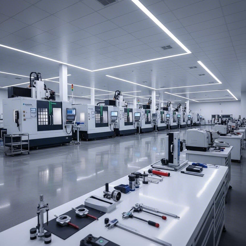
Evaluating Fabricator Capabilities and Equipment
When searching for metal fabricators near me or evaluating distant partners for heavy plate fabrication projects, equipment capability forms the foundation of your assessment. According to EVS Metal's contract fabrication guide, modern fiber laser systems cut 2-3x faster than older CO2 lasers and handle reflective materials that older systems struggle with. CNC press brakes with offline programming and automatic tool changers reduce setup time 40-60% versus manual systems.
But equipment alone doesn't tell the whole story. Consider these critical factors when evaluating a steel plate fabricator:
- Equipment age and technology: Modern machinery delivers faster processing, better precision, and more consistent results than outdated systems
- Capacity and scalability: Manufacturers with multiple machines accommodate production surges and provide backup capacity during maintenance—single-machine shops create bottlenecks
- Secondary services integration: Fabricators offering welding, finishing, and hardware installation provide single-source convenience versus managing multiple suppliers
- Geographic considerations: Multi-site manufacturers like those with facilities across multiple states provide geographic redundancy for disaster recovery and regional logistics advantages
For plate metal fabrication specifically, verify that the shop's press brakes handle your required tonnage and bed length. Ask about their plasma, laser, or waterjet cutting capacity relative to your plate thicknesses. A fabricator perfectly suited for sheet metal work may lack the heavy-duty equipment that structural steel & plate fab demands.
Certifications and Quality Systems That Matter
Certifications provide objective evidence that a fabricator maintains the quality systems your project requires. ISO 9001:2015 demonstrates quality management system maturity with documented procedures, corrective action processes, and management review. Industry-specific certifications indicate specialized experience with regulated manufacturing.
For automotive applications, IATF 16949 certification represents the global benchmark for quality management. This standard drives defect prevention rather than just detection, embedding risk analysis tools like Failure Mode and Effects Analysis (FMEA) throughout the manufacturing process. Suppliers holding IATF 16949 certification have demonstrated their commitment to zero-defects culture and continuous improvement—qualities that translate directly to reliability in your supply chain.
Beyond certifications, evaluate these quality indicators:
- Inspection capabilities: CMM inspection, optical comparators, and calibrated equipment enable first article inspection and ongoing dimensional verification
- Quality performance metrics: Request defect rates, on-time delivery performance, and customer satisfaction scores—established manufacturers track these systematically
- Nonconformance management: Documented processes for identifying, containing, and correcting quality issues prevent recurrence
- Traceability systems: Material certificates, welder identification, and complete quality records demonstrate process control
Streamlining Your Quote and Prototyping Process
The quoting phase reveals much about how a fabricator will perform during production. Responsive quote turnaround—ideally within 12-24 hours for straightforward projects—indicates efficient internal processes and adequate engineering bandwidth. Fabricators who take weeks to return quotes often struggle with production scheduling as well.
Provide complete information to receive accurate quotes:
- Part drawings or CAD files in standard formats
- Material specifications including grade and thickness
- Quantities per order and estimated annual volume
- Finish requirements and any special quality or inspection needs
- Context about the application and truly critical tolerances
According to Advantage Metal Products, rapid prototyping plays a crucial role in accelerating product development by validating design, functionality, and manufacturability before full-scale production begins. Techniques such as CNC machining allow rapid fabrication directly from CAD models, eliminating traditional tooling setups that consume time and cost.
The value of rapid prototyping extends beyond simple validation. It enables multiple design iterations, helping manufacturers and engineers refine part designs faster and ensure fitness for chosen manufacturing processes. For complex plate fabrication assemblies, prototype phases catch issues that would cost significantly more to address during production runs.
When evaluating prototyping capabilities, look for partners offering 5-day or faster turnaround on initial samples. This speed matters—every week saved in development translates to earlier market entry or project completion.
Fabricator Evaluation Checklist
Before committing to a structural steel and plate fabrication partner, systematically evaluate these criteria:
- ☐ Equipment capacity matches your thickness, size, and volume requirements
- ☐ Relevant certifications held (ISO 9001, IATF 16949, ASME, AWS as applicable)
- ☐ Demonstrated experience in your industry or similar applications
- ☐ Quote turnaround time meets your project timeline needs
- ☐ Rapid prototyping capabilities for design validation
- ☐ DFM support available during design phase
- ☐ Quality metrics (defect rates, on-time delivery) provided upon request
- ☐ Customer references available in similar applications and volumes
- ☐ Clear communication channels with dedicated project management
- ☐ Financial stability demonstrated through longevity or references
- ☐ Geographic location supports logistics requirements
- ☐ Capacity for scaling from prototype through production volumes
The Value of DFM Support and Engineering Collaboration
Experienced fabricators identify design issues causing manufacturing problems, quality defects, or unnecessary costs. Design for Manufacturability review should be standard practice during quoting—not an optional service you pay extra to receive.
According to EVS Metal, engineers who understand GD&T can recommend appropriate tolerance specifications—tighter than necessary increases costs 20-40% without functional benefit. This engineering expertise differentiates sophisticated fabricators from basic job shops.
What does comprehensive DFM support look like in practice? Your fabrication partner should:
- Review designs before quoting and identify potential manufacturing challenges
- Recommend material selections balancing cost, performance, and manufacturability
- Suggest modifications that maintain functionality while simplifying production
- Provide tolerance analysis considering real-world fabrication capabilities
- Offer guidance on nesting optimization and material utilization
For automotive applications where chassis, suspension, and structural components demand exceptional precision, partners like Shaoyi (Ningbo) Metal Technology exemplify these standards. Their combination of IATF 16949-certified quality systems, 5-day rapid prototyping, comprehensive DFM support, and 12-hour quote turnaround demonstrates the capabilities manufacturers should seek when evaluating metal fabrication partners for demanding applications.
Building Long-Term Fabrication Partnerships
The best fabrication relationships extend beyond individual projects. Long-term partnerships yield benefits that transactional purchasing cannot match: fabricators invest in understanding your applications, prioritize your orders during capacity constraints, and proactively suggest improvements based on accumulated knowledge.
Single-source partnerships simplify logistics and often lead to deeper engineering collaboration and better long-term cost control. However, many manufacturers balance this with two to three primary fabricators to provide price competition and production redundancy.
Whatever approach you choose, invest time in selecting partners whose capabilities, quality systems, and communication style align with your project requirements. The upfront effort in fabricator evaluation pays dividends throughout your project lifecycle—in quality, cost, and the confidence that your heavy plate fabrication work meets every specification you've established.
Frequently Asked Questions About Plate Fabrication
1. What does a plate fabricator do?
A plate fabricator cuts, shapes, and joins heavy metal materials typically 3/16 inch thick and above using specialized equipment. Their core operations include precision cutting through plasma, laser, waterjet, or oxy-fuel methods, forming thick plates using heavy-duty press brakes and rolling equipment, welding sections with multi-pass techniques suited for thick materials, and finishing surfaces to meet application specifications. Plate fabricators serve industries requiring structural strength including construction, pressure vessels, heavy equipment manufacturing, marine applications, and energy sector installations.
2. What is the process of plate fabrication?
The plate fabrication process involves four primary operations: cutting raw steel plates using thermal or cold-cutting methods based on thickness and precision requirements; forming through press brake bending or plate rolling to achieve desired shapes while managing springback and distortion; welding sections together using appropriate techniques like MIG or TIG with proper joint preparation and multi-pass strategies for thick materials; and finishing with surface treatments, coatings, or heat treatments as required. Heavy plate work often includes quenching and tempering processes that convert steel from austenite to martensite phase for enhanced hardness and wear resistance.
3. What is the difference between plate and sheet metal fabrication?
The primary distinction lies in material thickness. Sheet metal refers to thinner material cut from continuously rolled coils, typically used for appliances, enclosures, and lighter applications. Plate fabrication involves thicker materials starting at 3/16 inch (approximately 5mm) and reaching up to 150mm or more. This thickness difference requires fundamentally different equipment—heavy-duty press brakes with higher tonnage, specialized cutting systems, and welding procedures designed for multi-pass applications. Plate work serves heavy-duty purposes in structural steel, pressure vessels, heavy machinery, and marine construction where strength and durability are critical.
4. Which cutting method is best for thick steel plate?
The optimal cutting method depends on plate thickness, precision requirements, and material type. Plasma cutting excels for medium to thick plates up to 2 inches with excellent speed and versatility. Laser cutting delivers superior precision for plates under 1 inch with minimal heat-affected zones. Waterjet cutting handles heat-sensitive materials and maintains consistent tolerances on plates up to 200mm without thermal distortion. Oxy-fuel cutting remains the workhorse for the thickest materials, cutting steel plates up to 12 inches thick and processing 2-inch steel approximately three times faster than plasma for mild and low-alloy steels.
5. What certifications should a plate fabricator have?
Critical certifications depend on your application. ASME certification is essential for pressure vessel work, ensuring design, materials, welding, and inspection meet safety standards. AWS welding certifications verify welder competency on specific processes and positions. API standards govern storage tanks for petroleum products. For automotive applications, IATF 16949 certification demonstrates quality management systems focused on defect prevention. ISO 9001:2015 indicates general quality system maturity. Certified fabricators like Shaoyi (Ningbo) Metal Technology with IATF 16949 certification provide documented procedures, traceability, and quality controls that protect your investment in demanding applications.