 Small batches, high standards. Our rapid prototyping service makes validation faster and easier —

Sheet Metal Shearing And Bending: Why Material Choice Changes Everything
Understanding Sheet Metal Shearing and Bending Fundamentals
Ever wondered how a flat metal sheet transforms into the complex components you see in cars, appliances, and aircraft? The answer lies in two foundational processes that work hand in hand: sheet metal shearing and bending. Whether you're a manufacturing professional, engineer, or designer, mastering these techniques unlocks the full potential of metal fabrication.
This comprehensive guide covers both processes with equal depth, giving you the complete picture that most resources overlook. You'll discover how material choice dramatically affects outcomes and why understanding both operations together is essential for success.
Defining the Two Pillars of Metal Fabrication
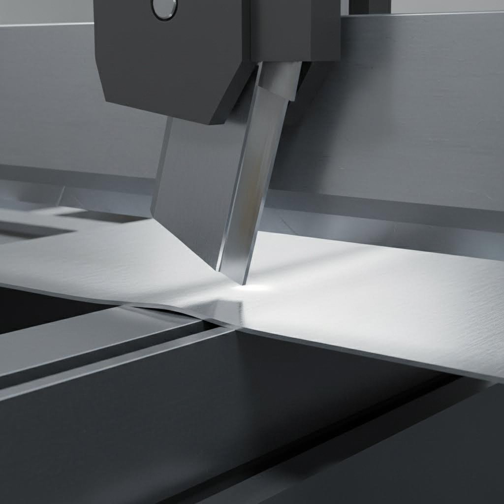
Sheet metal shearing is the process of cutting metal along a straight line using two opposing blades. Think of it like a giant pair of scissors designed specifically for metal. One blade remains stationary while the other descends with tremendous force, separating the material cleanly without producing chips or burning.
Sheet metal bending, on the other hand, deforms metal along a linear axis to create angles, channels, and three-dimensional shapes. According to AZ Metals, this process involves pressing a metal sheet at specific angles to produce components for automotive, aerospace, manufacturing, and countless other industries.
Here's what makes each process unique:
- Metal shearing: Removes material to create precise blanks and straight edges
- Sheet bending: Reshapes material without removing any metal
- Combined application: Creates functional parts from raw sheet stock
Why These Processes Work Together
Imagine trying to fold a piece of paper that hasn't been cut to size. You'd end up with uneven edges and wasted material. The same principle applies to metal fabrication. Accurate cutting before any bending operation is crucial for proper alignment and reduces material wastage.
The relationship between these processes follows a logical sequence. First, larger sheets are sheared into smaller, precisely sized blanks. Then, these blanks move to bending operations where they're transformed into finished components. This bending bending sequence ensures every piece fits intended specifications perfectly.
Shearing prepares the blank; bending transforms it into functional geometry.
Understanding both processes together matters because decisions made during shearing directly impact bending outcomes. The orientation of cuts affects grain direction, which influences how metal responds during forming. Similarly, knowing your final bend requirements helps you optimize blank dimensions during the cutting stage.
Throughout this article, you'll learn the mechanics behind each operation, discover material-specific techniques, and gain practical insights for integrating these processes into efficient workflows. Ready to dive deeper? Let's explore the science that makes it all possible.
The Mechanics Behind Metal Shearing Operations
What actually happens when a blade slices through steel? Understanding the physics behind shear cutting gives you the knowledge to achieve cleaner edges, reduce tool wear, and optimize your fabrication process. Let's break down the science that separates acceptable cuts from exceptional ones.
The Science of Shear Cutting
When you examine shearing at a molecular level, the process involves forcing metal past its ultimate shear strength. According to Ispat Guru, shearing occurs when a force is applied such that the shearing stress exceeds the ultimate shear strength of the material, causing the work metal to fail and separate at the cutting location.
The shearing sequence follows three distinct phases:
- Elastic deformation: As the upper blade contacts the metal surface, the material compresses slightly but can still return to its original shape if pressure is released
- Plastic deformation: Continued blade penetration causes permanent deformation as the metal yields, creating the characteristic burnished zone on the cut edge
- Fracture: Once the blade penetrates 30% to 60% of the material thickness, cracks initiate from both blade edges and propagate through the remaining material until complete separation occurs
The penetration depth before fracture varies significantly based on material properties. For low-carbon steel, the blade typically penetrates 30% to 60% of the thickness before fracture, with this range depending on the specific material thickness. More ductile metals like copper require deeper penetration, while harder materials fracture with less blade travel.
Hold-down clamps play a critical role in this process. According to Accurpress shear fundamentals, these clamps must depress just prior to the moving blade making contact with the material. This prevents the sheet from squirming or shifting during the shearing process, ensuring clean, accurate cuts.
How Blade Geometry Affects Cut Quality
The relationship between blade configuration and cut quality determines whether your sheared pieces meet specifications or require additional processing. Three geometric factors demand your attention: clearance, rake angle, and blade sharpness.
Blade Clearance refers to the gap between upper and lower blades as they pass each other. For optimum shearing quality, this clearance should be set at approximately 7% of the material thickness. What happens when clearance is wrong?
- Excessive clearance: Creates burred edges and can pull the workpiece between blades, potentially damaging the machine
- Insufficient clearance: Produces a double-cut appearance with secondary fractures and ragged edges
- Optimal clearance: Allows the material to fracture cleanly with minimal burr formation
Rake Angle describes the slope of the upper blade from left to right. This angle directly affects shearing force requirements and cut quality. Higher rake angles reduce the force needed but introduce problems. Sheer cutting at high rake angles substantially increases twist and bow in the cut-off piece, requiring longer stroke lengths and potentially creating material waste from distortion.
The key factors affecting shear quality include:
- Blade sharpness: Dull blades must penetrate further before fracture occurs, leaving less desirable cuts and increasing cutting pressure
- Clearance percentage: Typically 4% to 10% of material thickness for critical edge conditions, 9% to 15% when appearance is less important
- Material thickness: Thicker materials require adjusted clearances and lower hardness blades to prevent chipping
- Cutting speed: Speeds of 21 to 24 meters per minute produce cleaner edges in annealed metals, while low speeds create rougher finishes
Regarding thickness limitations, capabilities extend well beyond the 6mm maximum often cited for steel. D2 tool steel blades work effectively for cold shearing metals up to 6mm thick, while shock-resistant S-grade blades handle plates of 12.5mm and thicker. For aluminum alloys specifically, D2 blades have successfully sheared material up to 32mm thick depending on blade design and cut length.
Different materials require adjusted approaches. Stainless steels operate at 60% to 70% of a shear's rated mild steel capacity, while softer aluminum alloys can be sheared at 125% to 150% of rated capacity. Understanding these relationships between shearing material properties and machine settings ensures you select appropriate equipment and parameters for each job.
Now that you understand the mechanics behind shearing, you're ready to explore the different shearing methods available and when each one delivers optimal results.
Comparing Shearing Methods for Different Applications
Choosing the right shearing method can mean the difference between efficient production and costly rework. Each technique offers distinct advantages depending on your material, thickness requirements, and production volume. Let's examine the three primary approaches to cutting of sheet metal and help you determine which method fits your specific needs.
Guillotine Shearing for Straight Cuts
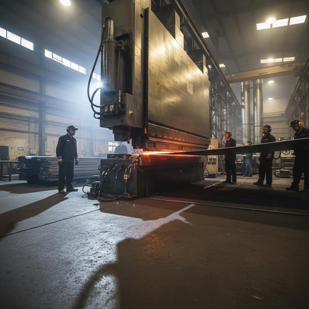
When precision and clean edges matter most, guillotine shearing stands as the industry standard. This method uses a large, sharp blade that moves vertically with tremendous force, slicing through metal placed on a stationary table below.
A hydraulic guillotine shear generates cutting force through fluid power systems, delivering consistent pressure across the entire blade length. According to ADHMT, these machines leverage hydraulic power to generate the force necessary to shear through metal, making them essential for various manufacturing and fabrication processes.
What makes hydraulic guillotine shears particularly valuable for high-volume production?
- Exceptional precision: The straight blade produces very accurate cuts, especially for straight lines and right angles
- Superior edge quality: Stationary blade positioning during cuts minimizes material shifting or warping
- Heavy-gauge capability: High force application easily handles plate shearing through thick materials
- Adjustable cutting angles: Modern guillotine shears offer angle adjustments for optimal cut quality across different materials
For plate shearing operations involving thicker materials, guillotine shears excel where other methods struggle. Machines rated for 12mm mild steel can typically handle up to 8mm stainless steel or 20mm aluminum, with cutting lengths ranging from 2000mm to 6000mm depending on the model.
The trade-off? Speed. Each cut requires the blade to descend, make the cut, and return to starting position. For extremely high-volume operations with thinner materials, this cycle time adds up.
When to Choose Rotary or Nibbling Methods
Not every job demands guillotine precision. Rotary shearing and nibbling each solve specific challenges that guillotine methods cannot address efficiently.
Rotary Shearing uses two cylindrical blades spinning against each other, feeding metal continuously between them. According to Liertech, one major advantage of rotary shearing is its speed, making it a great choice for high-volume production when churning out large numbers of sheet metal parts.
Rotary methods shine in specific scenarios:
- Continuous straight-line cutting without stopping
- Long production runs where speed trumps edge perfection
- Sheet shearing for thinner gauge materials
- Applications where minor edge finishing is acceptable
Nibbling takes a completely different approach, using a small punch that rapidly removes material in overlapping bites. This method handles what the others cannot: curves, complex shapes, and interior cutouts without requiring expensive custom tooling.
Consider nibbling when your cutting of sheet metal involves irregular patterns, prototypes requiring quick turnaround, or situations where laser cutting isn't available or cost-effective.
Method Comparison at a Glance
The following table breaks down how each shearing method performs across the dimensions that matter most for your decision:
| Dimension | Guillotine Shearing | Rotary Shearing | Nibbling |
|---|---|---|---|
| Cut Type | Straight lines, right angles | Continuous straight lines | Curves, complex shapes, interior cuts |
| Material Thickness Range | Up to 20mm+ for mild steel; optimal for heavy gauge | Thin to medium gauge; thin gauge; typically under 3.2mm | Thin gauge only; typically under 3mm |
| Edge Quality | Excellent; clean, sharp edges with minimal burr | Good; may require finishing for precision work | Fair; scalloped edges require secondary finishing |
| Speed | Moderate; limited by blade cycle time | Fast; continuous operation ideal for volume | Slow; depends on cut complexity and length |
| Best Applications | Precision blanks, thick plate cutting, aerospace and automotive parts | High-volume production, appliance manufacturing, automotive body panels | Prototypes, custom shapes, ventilation patterns, small batches |
Making the Right Choice for Your Requirements
Your decision should balance several factors. Ask yourself these questions:
- What's your material thickness? Plate shearing for materials over 6mm almost always requires guillotine methods. Thinner gauges open up rotary and nibbling options.
- How critical is edge quality? If sheared metal moves directly to welding or visible assemblies, guillotine edges save finishing time. Secondary operations can clean up rotary or nibbled edges when appearance matters less.
- What's your production volume? High-volume straight cuts favor rotary speed. Moderate volumes with precision needs suit guillotine shears. Low volumes with complex shapes make nibbling cost-effective.
- Do you need curved or interior cuts? Only nibbling handles these without expensive tooling, though laser cutting often proves more efficient for complex geometries.
Many metal shearing and cutting machines in modern fabrication shops combine multiple capabilities. Hybrid equipment can switch between methods depending on the job, though dedicated machines typically outperform multi-function alternatives in their specialty.
Understanding these trade-offs prepares you for the next critical decision: selecting the right bending technique to transform your accurately sheared blanks into functional components.
Sheet Metal Bending Methods and Techniques Explained
Now that your blanks are precisely sheared, what happens when you need to transform flat metal into three-dimensional components? Sheet metal bending processes involve far more than simply forcing material into a new shape. Understanding the science behind each technique helps you select the right method, predict material behavior, and achieve consistent results every bend.
Understanding Bend Allowance and Springback
Ever noticed how a sheet metal bend never stays exactly where you put it? This phenomenon, called springback, occurs because metal has elastic memory. When you release pressure after bending, the material partially returns toward its original flat state.
According to The Fabricator, when a sheet metal part is bent, it physically gets bigger. The final formed dimensions will be greater than the sum total of the outside dimensions shown on the print unless some allowance for the bend is taken into account. The metal doesn't actually stretch—it elongates because the neutral axis shifts closer to the inside surface of the material.
The neutral axis is the area within the bend where material experiences no physical change during forming. Here's what happens on each side:
- Outside the neutral axis: Material expands under tension
- Inside the neutral axis: Material compresses
- Along the neutral axis: No expansion, no compression—nothing changes
As this neutral axis shifts inward, more material expands on the outside than compresses on the inside. This imbalance is the root cause of springback. Different materials spring back by different amounts, requiring adjusted overbend angles to achieve target dimensions.
The bend allowance formula accounts for this behavior: BA = [(0.017453 × Inside radius) + (0.0078 × Material thickness)] × Bend angle. For most applications, a K-factor of 0.446 works across material types including mild steel, stainless, and aluminum, representing where the neutral axis relocates during forming.
A fundamental rule of thumb states that bend radius should equal or exceed material thickness. This guideline prevents cracking on the outer surface where tension is highest. However, practical application requires additional considerations:
- Harder materials need larger minimum radii than softer ones
- Bending perpendicular to grain direction allows tighter radii
- Work-hardened materials require even more generous radii
- Material condition (annealed versus tempered) significantly affects minimum bend capability
Air Bending Versus Bottom Bending Techniques
Three primary sheet metal bending methods dominate fabrication shops, each offering distinct advantages depending on your precision requirements, material properties, and production volume.
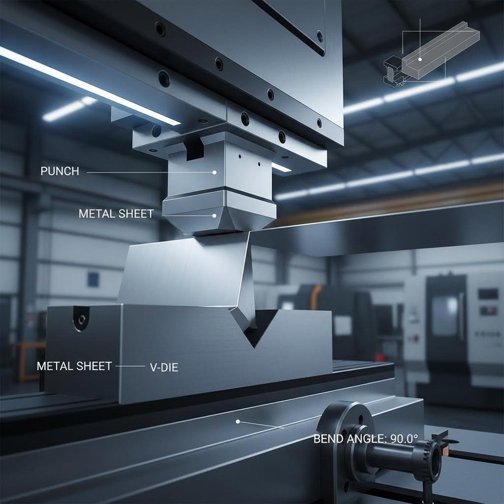
Air Bending represents the most versatile approach. According to ADHMT, air bending is a bending method featuring minimum contact between the metal and tools. The factor that determines the bend angle is how far the punch descends into the die, using the leverage principle to achieve bends with relatively small force.
When air bending sheet metal, you'll notice these key characteristics:
- Three-point contact: Only the punch tip and both die shoulders touch the material
- Lower tonnage requirements: Typically requires less force than other methods
- Angle flexibility: One die can produce multiple angles by varying punch depth
- Springback presence: Requires compensation since metal isn't fully formed to die shape
- Reduced tool wear: Limited contact extends tooling life
Bottom Bending (also called bottoming) presses the sheet metal closer to the die surface but doesn't achieve complete conformity. This sheet metal bending method needs more tonnage than air bending—roughly two to three times more—but delivers improved angle consistency.
Bottom bending characteristics include:
- Increased contact area: Material presses against die walls more fully
- Reduced springback: Closer die conformity means less elastic recovery
- Sharper-angle tooling required: Using 88° tooling to achieve 90° final angles compensates for remaining springback
- Better repeatability: More consistent angles across production runs
Coining applies overwhelming force—five to ten times that of air bending—to completely eliminate springback. The punch drives material fully into the die, creating plastic flow that destroys the metal's elastic memory. What you see in the die is exactly what you get in the finished part.
When does coining make sense? Consider it for:
- Applications demanding tolerances better than ±0.5°
- High-volume production where consistency outweighs higher tooling costs
- Safety-critical components where angle variation cannot be tolerated
- Automated assembly lines requiring zero dimensional variation
How Grain Direction Affects Your Bends
Every sheet metal bend decision should account for material grain direction—the orientation of crystalline structure created during rolling. Ignoring grain direction invites cracking, inconsistent springback, and premature failure.
The golden rule: orient bend lines perpendicular to grain direction whenever possible. Bending across the grain allows material to flow more uniformly, reducing stress concentration on the outer surface. When bending parallel to grain, those elongated crystal structures resist deformation and crack more readily.
Practical implications for part design include:
- Nest parts strategically: Position blanks during shearing so bend lines cross grain at optimal angles
- Increase radii for parallel bends: When grain-parallel bending is unavoidable, use larger radii to reduce cracking risk
- Specify requirements on drawings: Critical parts should indicate required grain orientation relative to bend lines
- Consider annealed material: Heat treatment can reduce grain-direction sensitivity for complex parts
Understanding these sheet metal bend fundamentals prepares you to tackle the next challenge: adapting your techniques for specific materials. Aluminum, stainless steel, and carbon steel each respond differently to the same bending parameters.
Material-Specific Guidance for Shearing and Bending
Ever wondered why the same bending technique that works perfectly on steel produces cracked edges on aluminum? Or why stainless steel blanks require completely different shear settings than carbon steel? Material selection fundamentally changes how you approach both processes. Understanding these differences eliminates guesswork and prevents costly mistakes.
When someone asks, "how do I cut sheet metal effectively?" the honest answer depends entirely on what metal they're working with. Let's explore what makes each material unique and how to adjust your techniques accordingly.
How Aluminum Responds Differently Than Steel
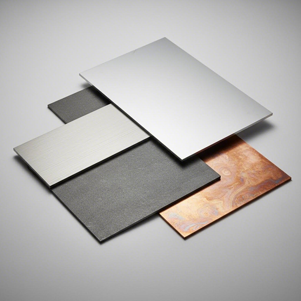
Aluminum and steel may look similar on the surface, but their behavior during fabrication couldn't be more different. According to Aluminum Bending Machine, steel has excellent plastic deformation capability with minimal springback, while aluminum exhibits higher elasticity, leading to more noticeable springback—especially in 6000 and 7000 series alloys.
What does this mean for your shop floor operations?
- Springback compensation: When bending steel sheet, you might overbend by 2° to 3° to achieve target angles. Aluminum often requires 5° to 8° of compensation depending on alloy and temper
- Surface sensitivity: Aluminum scratches easily. Shearing metal requires smooth rollers—often nylon or polyurethane-coated—rather than the hardened steel rollers used for carbon steel
- Fracture risk: Aluminum profiles are prone to surface cracks, especially in thin-walled sections or high-alloy materials. Steel typically doesn't fracture during bending but may become brittle at low temperatures
- Force requirements: Aluminum is softer and easier to bend, requiring significantly less tonnage than steel of equivalent thickness
For anyone wondering "how do I bend aluminum" without problems, the key lies in pre-bending and compensation. According to the same source, aluminum profiles often require post-bending adjustments to eliminate springback errors. CNC systems combined with simulation software help predict and compensate for this elastic recovery before the first part is formed.
Shear clearance settings also differ substantially. Aluminum's softness allows shearing at 125% to 150% of a machine's rated mild steel capacity, but the trade-off is edge quality. Excessive clearance creates significant burrs on aluminum that require secondary finishing.
Working with Stainless Steel and Copper
Stainless steel presents unique challenges that catch many fabricators off guard. Its work-hardening characteristics mean the material gets progressively harder as you form it. What implications does this have?
- Reduced shear capacity: Stainless steels operate at only 60% to 70% of a shear's rated mild steel capacity despite similar appearance
- Larger bend radii required: According to Xometry, stainless steel generally requires a minimum bend radius of 0.5 times the material thickness—larger than carbon steel's typical 0.4t minimum
- Higher bending forces: Work hardening increases tonnage requirements as the bend progresses
- Tool wear acceleration: The harder material surface wears tooling faster than carbon steel operations
Copper and its alloys behave differently still. Being highly ductile, copper bends easily with minimal springback and allows very tight radii. However, its softness creates challenges during shearing metal operations. Excessive blade pressure can deform the material before cutting, and improper clearance produces significant edge distortion.
Bending steel sheet remains the baseline against which other materials are measured. Steel sheet bending offers predictable behavior: moderate springback, consistent force requirements across thickness ranges, and forgiving tolerances for clearance settings. Most fabricators learn their craft on carbon steel before adapting techniques for more challenging materials.
Material Parameters at a Glance
The following table provides essential reference values for adjusting your equipment and techniques based on material selection:
| Parameter | Aluminum (6061-T6) | Stainless Steel (304) | Carbon Steel (1018) | Copper (C11000) |
|---|---|---|---|---|
| Minimum Bend Radius | 2.0t to 3.0t | 0.5t to 0.75t | 0.4t to 0.5t | 0.25t to 0.5t |
| Recommended Shear Clearance | 8% to 10% of thickness | 5% to 7% of thickness | 6% to 8% of thickness | 4% to 6% of thickness |
| Springback Factor | High (5° to 8° overbend) | Moderate (3° to 5° overbend) | Low (2° to 3° overbend) | Very Low (1° to 2° overbend) |
| Special Considerations | Use soft rollers; prone to surface cracks; requires springback compensation | Work hardens rapidly; reduce shear capacity to 60%-70%; larger radii needed | Baseline material; predictable behavior; standard tooling works well | Very ductile; deforms easily under pressure; excellent formability |
How Thickness Affects Both Processes
Material thickness compounds these behavioral differences. According to Xometry, thicker sheets require larger bend radii to avoid cracking or damaging the material because bending induces tensile and compressive stresses. Thicker sheets are less flexible and more prone to cracking if the bend radius is too small.
The relationship between thickness and process parameters follows these patterns:
- V-die opening: Increases with thickness to allow material flow without cracking
- Bending force: Increases exponentially with thickness—doubling thickness roughly quadruples required tonnage
- Minimum flange length: Must increase proportionally to prevent die marks and ensure clean bends
- Shear clearance absolute value: While percentage remains constant, actual gap increases with thicker material
For practical application, always consult air bend force charts that correlate thickness with die opening, flange requirements, and tonnage. These charts eliminate guesswork and prevent equipment damage from exceeding capacity.
Understanding material-specific behaviors positions you to integrate shearing and bending into efficient production sequences. The next section explores how these processes work together in real manufacturing workflows.
Integrating Shearing and Bending in Your Fabrication Workflow
How do successful fabrication shops transform raw sheet stock into finished components without wasted motion or rework? The answer lies in understanding how shearing and bending connect within a logical production sequence. Getting this workflow right means faster turnaround, fewer quality issues, and lower per-part costs.
The Typical Fabrication Sequence from Blank to Part
Every finished metal component follows a predictable path from raw material to shipping dock. Understanding this sequence helps you identify bottlenecks and optimize each step for maximum efficiency.
According to Phillips Corp, proper preparation techniques involve cleaning the sheet metal, optimizing the cutting parameters, and ensuring the correct setup of the bending tools. This preparation stage sets the foundation for everything that follows.
Here's how a typical workflow progresses:
- Material selection and verification: Confirm material type, thickness, and grain direction match specifications before processing begins
- Shearing sheet metal to size: Cut raw stock into precisely dimensioned blanks, accounting for bend allowances calculated during design
- Deburring and edge preparation: Remove sharp edges and burrs from sheared blanks to prevent operator injury and ensure clean bends
- Forming operations: Transfer blanks to press brakes or folding machines where bending transforms flat pieces into three-dimensional shapes
- Secondary operations: Complete any additional processes such as welding, hardware insertion, or surface finishing
- Quality inspection: Verify dimensions, angles, and surface quality against specifications before release
The critical insight? Steel shearing quality directly impacts bending outcomes. A blank with uneven edges or dimensional errors creates problems that compound through every subsequent operation. Taking extra time during cutting prevents exponentially larger problems downstream.
Optimizing Your Process Flow
Modern fabrication increasingly combines sheet metal laser cutting and bending for complex geometries that traditional shearing cannot achieve. According to Phillips Corp, laser cutting offers highly accurate and efficient processing that creates precise cuts with minimal heat-affected zones, making it ideal for intricate patterns before bending operations.
When should you choose shearing steel versus laser cutting? Consider these decision factors:
- Part complexity: Straight cuts favor traditional shearing; curves and cutouts require laser or nibbling
- Production volume: High-volume straight blanks benefit from shearing speed; mixed geometries suit laser flexibility
- Tolerance requirements: Laser cutting achieves tighter tolerances but at higher per-part cost
- Material thickness: Thick plate shearing remains more economical than laser for simple shapes
Many shops now route parts through a bending center that integrates material handling, forming, and inspection into a single automated cell. These systems reduce handling time between operations and maintain consistent quality across production runs.
Quality control measures span both processes. For shearing, inspect cut edge quality, dimensional accuracy, and squareness. For bending, verify angles using calibrated protractors or digital angle finders, check bend locations against drawings, and confirm overall part dimensions fall within tolerance.
According to Cumulus Quality, quality assurance measures include thorough inspection of raw materials, in-process monitoring, dimensional verification, and post-fabrication testing. Working with experienced fabricators and adhering to industry standards ensures the quality and consistency of fabricated parts.
Designs must focus on minimizing complex shapes, optimizing nesting layouts to reduce material waste, and incorporating bend radii to avoid cracks or distortions. Common mistakes to avoid include inadequate material clamping, improper programming, and ignoring safety precautions.
With your workflow optimized, one critical area remains: ensuring every operator follows proper safety protocols while avoiding the most common fabrication errors.
Safety Standards and Best Practices for Metal Fabrication
What separates a productive fabrication shop from one plagued by injuries and rework? The answer often comes down to safety protocols and error prevention. Whether you're operating a hydraulic guillotine shear or forming complex angles on a press brake, understanding the hazards—and how to avoid them—protects both operators and production quality.
Shear safety and proper bending of metal techniques aren't just regulatory requirements. They're practical investments that reduce downtime, prevent costly mistakes, and keep your team working efficiently. Let's explore the essential protocols that experienced fabricators follow every day.
Essential Safety Protocols for Shearing Equipment
Shearing machines rank among the most dangerous equipment in any fabrication shop. According to AMADA's Shearing Machine Safety Guide, employers must take necessary safety measures to prevent possible hazards caused by shearing machines, including measures to prevent body parts from entering the hazardous area.
The finger protector serves as your first line of defense. This guard prevents operators from reaching below the hold-downs and toward the blades during operation. AMADA emphasizes that the maximum opening height of the finger protector is determined by the maximum worksheet thickness—never increase this height beyond specifications.
Two-hand control devices add another critical layer of protection. These stand-type controls require operators to keep both hands engaged on buttons positioned away from the point of operation. You physically cannot have your hands near the blades while activating the machine.
What about protecting workers at the rear of the machine? Rear light-curtain systems immediately stop ram or backgauge movement when light beams are obstructed. This feature is especially effective for protecting operators other than the main operator who may approach from behind.
Operator Safety Checklist
- Before each shift: Inspect finger protectors for damage and verify proper opening height settings
- Check guards: Confirm all safety guards are in place and functioning before powering on equipment
- Verify controls: Test two-hand control devices and emergency stop buttons at multiple locations
- Assess material handling: Use proper lifting techniques and mechanical aids for heavy sheets
- Lock out procedures: When working within the operating range of moving parts, turn off and lock out electric power, compressed air, and hydraulic power
- Keep the key: Remove the key from the keyswitch and keep it with you during maintenance
- Tag equipment: Notify all workers on site that maintenance work is ongoing using visible tags
- Wear PPE: Use appropriate gloves, safety glasses, and hearing protection as required
Preventing Common Bending Errors
Understanding how to metal bend correctly goes beyond knowing machine settings. According to Woodward Fab, slight mistakes in bending operations can lead to product damage, dimensional inaccuracies, material loss, and wasted time and effort. In extreme conditions, operator safety may be jeopardized.
What mistakes cause the most problems? Let's examine the critical errors and their prevention:
Incorrect Bend Sequence: Bending parts in the wrong order creates access problems for subsequent bends. Always plan your sequence so earlier bends don't interfere with tooling clearance for later operations. Map out the complete forming sequence before making the first bend.
Inadequate Tooling Selection: Using the wrong die opening or punch radius for your material thickness leads to cracking, marking, or dimensional errors. Match tooling to material specifications—consult tonnage charts and minimum flange length requirements before setup.
Ignoring Grain Direction: Bended metal fails when bend lines run parallel to grain direction in susceptible materials. Orient blanks during shearing so critical bends cross the grain at optimal angles. When parallel bends are unavoidable, increase bend radii to compensate.
Feature Distortion: Holes, slots, or other features too close to bend lines deform during forming. Maintain minimum distances between features and bend locations based on material thickness and bend radius.
Improper Flange Length: Flanges that are too short slip during bending, creating inconsistent angles and potential safety hazards. Calculate minimum flange requirements using the formula: minimum flange = (die opening ÷ 2) + material thickness.
Maintenance Requirements That Protect Safety and Quality
Regular maintenance directly affects both operator safety and part quality. Dull blades require more force, increasing stress on machine components and creating unpredictable cutting behavior. Worn dies produce inconsistent angles and can cause material slippage.
AMADA's safety guidelines specify that employers must conduct periodic voluntary inspection once or more per year, repair any problems found, and file inspection results and repair records for three years. Daily pre-shift inspections should also verify equipment condition before starting work.
Key maintenance practices include:
- Blade inspection: Check for chips, wear, and proper alignment before each production run
- Lubrication: Frequent cleaning and lubrication prevent jamming and frictional wear; automated lubrication systems ensure consistency
- Hydraulic system checks: Monitor fluid levels, filter condition, and pressure settings regularly
- Backgauge calibration: Verify positioning accuracy to maintain dimensional consistency
- Safety device testing: Regularly test light curtains, interlocks, and emergency stops to confirm proper function
Investing time in safety protocols and preventive maintenance pays dividends in reduced injuries, consistent quality, and higher productivity. With these fundamentals in place, you're positioned to make informed decisions about whether to build in-house capabilities or partner with professional fabrication services.
Choosing Professional Sheet Metal Bending Services
Should you invest in expensive equipment and skilled operators, or partner with specialists who already have both? This question faces every manufacturer considering sheet metal bending services. The right answer depends on your specific situation—production volumes, quality requirements, available capital, and core business focus all play critical roles in this decision.
Understanding when outsourcing makes strategic sense versus when in-house capabilities deliver better value helps you allocate resources effectively. Let's examine the key factors that should guide your make-versus-buy decision.
When to Outsource Your Fabrication Needs
According to EVS Metal, contract sheet metal fabrication enables companies to manufacture metal components and assemblies without capital investment in equipment, facilities, or specialized workforce. This fundamental advantage drives many outsourcing decisions.
When does a sheet metal bending service make more sense than building internal capabilities? Consider outsourcing when:
- Variable production volumes: Demand fluctuates seasonally or project-by-project, making equipment utilization unpredictable
- Capital constraints: Limited budgets cannot support equipment purchases that may cost hundreds of thousands of dollars
- Specialized capabilities needed: Advanced processes like automated powder coating, robotic welding, or precision sheet steel bending require expertise your team lacks
- Workforce challenges: Skilled fabrication operators are difficult to hire and retain in your region
- Speed to market priority: New products need rapid prototyping without waiting months to install and qualify new equipment
Conversely, in-house manufacturing often makes sense when you have consistent high volumes that justify equipment investment, when fabrication represents a core differentiating capability, or when proprietary processes require absolute confidentiality.
Most companies find that steel bending and fabrication works best as an outsourced function. According to EVS Metal, companies typically reserve internal manufacturing for core differentiating capabilities only, letting specialists handle metal components and assemblies more efficiently.
Evaluating Service Provider Capabilities
Not all fabrication partners deliver equal value. Evaluating potential providers requires assessment across multiple dimensions to ensure they can meet your quality, timeline, and cost requirements consistently.
Equipment and Technology directly impacts what's possible and at what cost. According to EVS Metal, modern fiber laser systems cut 2–3x faster than older CO2 lasers and handle reflective materials that older systems struggle with. CNC press brakes with offline programming and automatic tool changers reduce setup time 40–60% versus manual systems. Ask prospective partners about equipment age, technology level, and capacity for your specific materials and thicknesses.
Quality Certifications indicate systematic quality management maturity. ISO 9001:2015 demonstrates documented procedures, corrective action processes, and management review as a baseline. According to RapidDirect, industry-specific certifications matter for regulated applications: AS9100 for aerospace, ISO 13485 for medical devices, and IATF 16949 for automotive components.
For automotive applications specifically, IATF 16949 certification is essential. This standard ensures fabricators meet the rigorous quality requirements that automotive OEMs demand for chassis, suspension, and structural components. Manufacturers like Shaoyi (Ningbo) Metal Technology hold this certification, demonstrating their capability to support precision sheet metal work for automotive supply chains.
Design for Manufacturability (DFM) Support separates sophisticated partners from basic job shops. According to EVS Metal, experienced fabricators identify design issues causing manufacturing problems, quality defects, or unnecessary costs. DFM review should be standard practice during quoting, not an optional service. Engineers who understand GD&T can recommend appropriate tolerance specifications—tighter than necessary increases costs 20–40% without functional benefit.
Turnaround Time and Prototyping capabilities determine how quickly you can iterate designs and respond to market demands. Standard lead times range from 3–5 days for simple parts to 1–2 weeks for painted, coated, or assembled components according to RapidDirect's industry analysis. For rapid prototyping needs, some manufacturers offer expedited services—Shaoyi, for example, delivers 5-day rapid prototyping with 12-hour quote turnaround, enabling faster design validation before committing to production tooling.
Key Evaluation Criteria for Service Providers
When comparing potential partners, use this comprehensive checklist to ensure thorough evaluation:
- Certifications: Verify ISO 9001:2015 at minimum; confirm industry-specific certifications (IATF 16949, AS9100, ISO 13485) match your application requirements
- Equipment capabilities: Assess whether their machinery handles your material types, thicknesses, and complexity levels
- Capacity and scalability: Confirm they can accommodate production surges and provide backup capacity during maintenance periods
- Geographic considerations: Multi-facility manufacturers provide redundancy and regional logistics advantages; proximity may matter for site visits and communication
- Engineering support: Look for direct access to engineers for DFM discussions, tolerance questions, and problem solving
- Volume flexibility: Ensure they efficiently handle your typical batch sizes, whether 10 pieces or 5,000
- Secondary services: Evaluate whether they offer welding, finishing, and hardware installation as single-source convenience
- Quality metrics: Request defect rates, on-time delivery performance, and customer satisfaction scores
- Financial stability: Companies operating 15+ years demonstrate sustained market competitiveness
- Customer references: Contact 3–5 customers in similar applications about communication quality, problem resolution, and delivery performance
Understanding how to bend a metal part correctly requires expertise that takes years to develop. When evaluating whether a provider truly understands the nuances of different materials, ask about their experience with your specific alloys and thicknesses. Request sample parts or first article inspection reports demonstrating capability with similar work.
The right fabrication partner becomes an extension of your engineering team, offering technical guidance that improves designs while meeting production requirements. Whether you need prototype quantities or automated mass production, matching your needs to provider capabilities ensures successful outcomes for every project.
Frequently Asked Questions About Sheet Metal Shearing and Bending
1. What is the shearing process in sheet metal?
Shearing is a mechanical cutting process that separates sheet metal along a straight line using two opposing blades. One blade remains stationary while the other descends with force, fracturing the material without producing chips or using heat. The process involves three phases: elastic deformation, plastic deformation, and fracture. For optimal results, blade clearance should be approximately 7% of material thickness, and proper hold-down clamps must engage before cutting to prevent material shifting.
2. What are the rules of thumb for bending sheet metal?
The fundamental rule states that bend radius should equal or exceed material thickness to prevent cracking. For example, 1mm thick sheet requires a minimum 1mm bend radius. Additional guidelines include orienting bend lines perpendicular to grain direction, using larger radii for harder materials, and calculating proper bend allowance using the formula: BA = [(0.017453 × Inside radius) + (0.0078 × Material thickness)] × Bend angle. A K-factor of 0.446 works across most material types.
3. What is the difference between bending and shearing sheet metal operations?
Shearing removes material by cutting metal sheets into smaller pieces along straight lines, leaving the remaining metal unchanged in form. Bending modifies the shape without removing any material, creating angles and three-dimensional forms through plastic deformation. These processes work together in sequence—shearing prepares precisely sized blanks that then move to bending operations for transformation into functional components.
4. How do I choose between air bending, bottom bending, and coining?
Air bending offers the most versatility with lower tonnage requirements and angle flexibility using one die for multiple angles, but requires springback compensation. Bottom bending uses 2-3 times more tonnage but delivers improved angle consistency with reduced springback. Coining applies 5-10 times the force of air bending to completely eliminate springback, ideal for tolerances better than ±0.5° and high-volume production requiring zero dimensional variation.
5. When should I outsource sheet metal fabrication versus building in-house capabilities?
Outsourcing makes sense when production volumes fluctuate, capital is limited, specialized capabilities are needed, or skilled operators are scarce. In-house manufacturing suits consistent high volumes justifying equipment investment, core differentiating capabilities, or proprietary processes requiring confidentiality. IATF 16949-certified manufacturers like Shaoyi offer 5-day rapid prototyping, DFM support, and 12-hour quote turnaround for automotive applications without capital investment in equipment.