 Small batches, high standards. Our rapid prototyping service makes validation faster and easier —

Sheet Metal Fabrication For Aerospace: From Raw Alloy To Flight-Ready Parts
Understanding Sheet Metal Fabrication in Aerospace Manufacturing
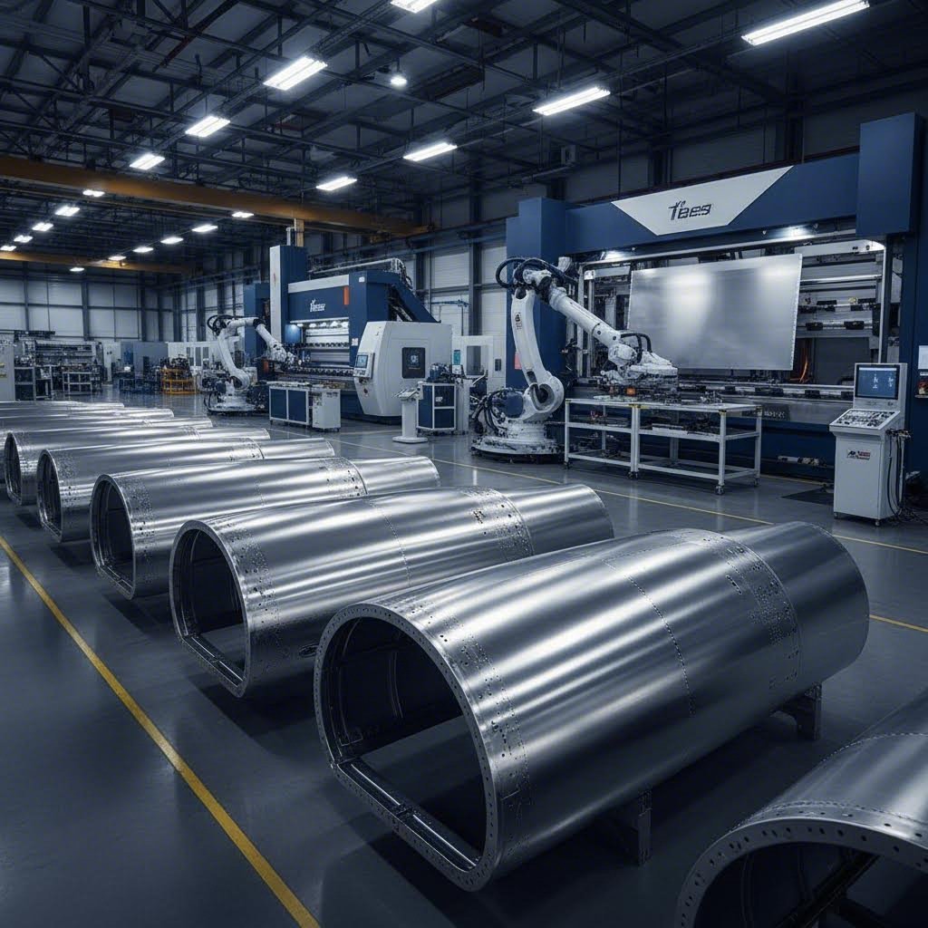
Imagine a commercial airliner cruising at 35,000 feet. Every fuselage panel, structural bracket, and engine casing protecting passengers started as a flat sheet of specialized alloy. Sheet metal fabrication for aerospace transforms these raw materials into flight-critical components through precision cutting, forming, and finishing processes that meet the industry's most demanding standards.
Aerospace sheet metal fabrication refers to the specialized manufacturing processes used to shape, cut, and assemble metal sheets into components for aircraft and spacecraft. Unlike general industrial fabrication, this discipline operates under extraordinarily tight tolerances and rigorous quality requirements. You'll find fabricated sheet metal throughout modern aircraft, from the aluminum skin panels that form the fuselage to titanium engine components that withstand extreme temperatures.
Why Aerospace Demands Uncompromising Precision
Why does precision matter so much in aerospace fabrication? The answer lies in the unforgiving environment these components must endure. Aircraft sheet metal parts experience repeated pressurization cycles, temperature extremes ranging from -60°F at altitude to hundreds of degrees near engines, and constant vibration throughout their service life.
A minor defect or dimensional inconsistency that might be acceptable in other industries could prove catastrophic in aviation. Parts must be strong yet lightweight, perfectly shaped to optimize aerodynamics, and manufactured with absolute consistency across production runs.
In aerospace manufacturing, precision isn't merely a quality goal—it's the foundation of passenger safety and mission success. Every fabricated component represents a link in the chain of airworthiness that cannot fail.
This uncompromising approach to precision enables manufacturers to produce parts that can handle the stresses of flight while maintaining reliability over thousands of flight cycles.
The Foundation of Modern Aircraft Manufacturing
Aerospace fabrication serves as the backbone of both commercial and military aviation manufacturing. Whether you're examining a passenger jet or a military fighter, fabricated sheet metal components form essential structural elements that directly impact performance, safety, and regulatory compliance.
Commercial aviation prioritizes passenger safety, fuel efficiency, and long-term durability. Military aerospace standards, however, add requirements for combat survivability, rugged design, and operation under extreme conditions including high altitudes, temperature variations, and mechanical stress. According to Visure Solutions, mil-spec components must endure combat stress, electromagnetic interference, and environmental extremes that exceed standard FAA-compliant aviation requirements.
Both sectors rely on certified quality management systems like AS9100D certification, which includes 105 additional requirements beyond ISO 9001 specifically addressing aerospace concerns such as production control, counterfeit parts prevention, and product safety.
In the sections ahead, you'll discover the specific materials, techniques, and quality standards that transform raw aerospace alloys into flight-ready components. From aluminum and titanium alloy selection to advanced forming processes and rigorous inspection protocols, each element plays a vital role in delivering parts that meet aviation's highest standards.
Aerospace-Grade Materials and Alloy Selection
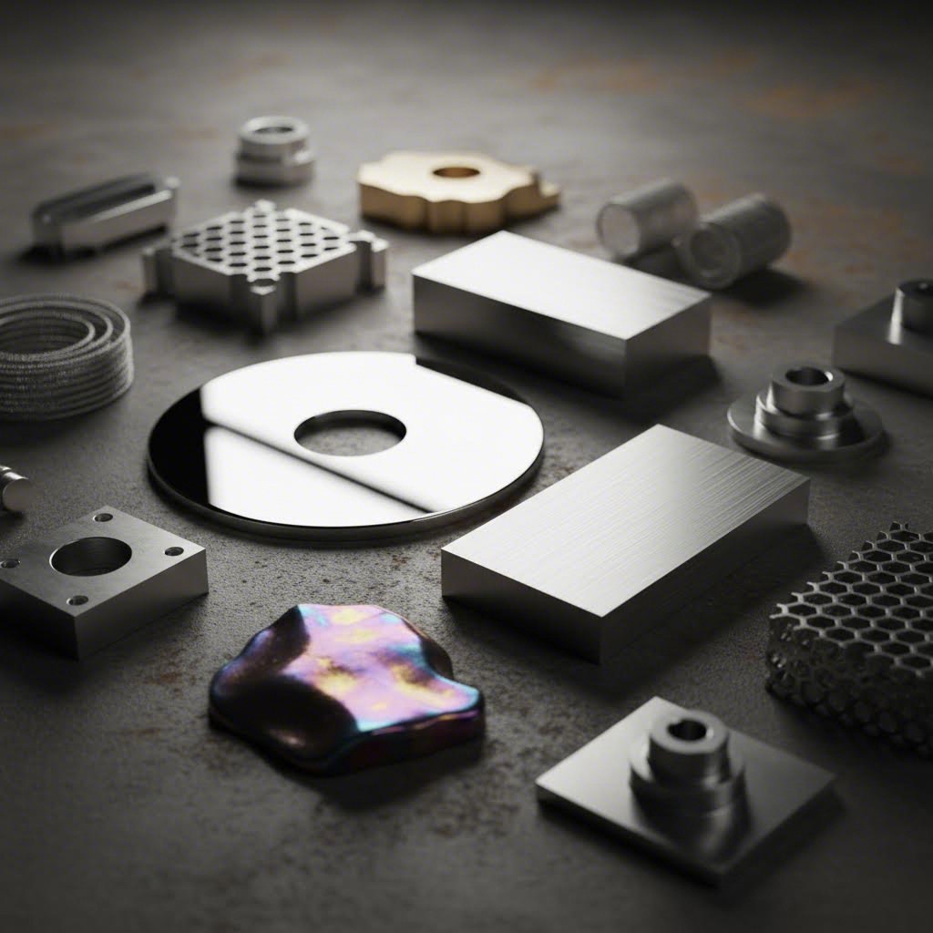
What separates an aircraft component from an ordinary metal part? The answer begins with material selection. When an aircraft component is fabricated from an aluminum alloy, titanium, or nickel superalloy, engineers aren't simply choosing a metal—they're selecting a precisely formulated material engineered to perform under conditions that would destroy conventional metals.
Aerospace metal fabrication demands alloys that deliver exceptional strength while minimizing weight, resist corrosion across decades of service, and maintain structural integrity through temperature extremes. Understanding these material specifications helps you appreciate why metal aerospace components command such rigorous manufacturing standards.
Aluminum Alloys for Structural and Fuselage Applications
Aluminum alloys dominate aircraft construction, accounting for approximately 80% of a typical commercial aircraft's material composition. Two grades stand out for sheet metal applications: 2024-T3 and 7075-T6.
2024-T3 Aluminum has earned its reputation as the workhorse of aerospace fuselage construction. The "T3" designation indicates solution heat treatment followed by cold working—a process that optimizes the alloy's mechanical properties. With copper as its primary alloying element, 2024-T3 delivers excellent fatigue resistance, making it ideal for structures experiencing repeated stress cycles during flight.
You'll find 2024-T3 in fuselage skin panels, wing structures, and areas where repeated pressurization cycles demand superior fatigue performance. According to Premium Aluminum's technical comparison, this alloy offers good machinability and formability, allowing manufacturers to create complex curved sections without cracking.
7075-T6 Aluminum represents one of the strongest aluminum alloys available. Its high zinc content delivers tensile strength approaching that of many steels while maintaining aluminum's weight advantage. The T6 temper indicates solution heat treatment followed by artificial aging, maximizing the alloy's strength characteristics.
Where does 7075-T6 excel? Structural brackets, wing spars, and load-bearing components where maximum strength matters more than fatigue resistance. However, this strength comes with trade-offs—7075 exhibits lower corrosion resistance than 2024 and proves more challenging to machine and form.
High-Performance Titanium and Nickel Superalloys
When aluminum can't handle the heat, aerospace engineers turn to titanium and nickel-based superalloys. These materials cost significantly more but deliver performance characteristics essential for engine components and high-stress applications.
Ti-6Al-4V (Grade 5 Titanium) combines titanium with 6% aluminum and 4% vanadium, creating an alloy with an exceptional strength-to-weight ratio. According to Huaxiao Metal's technical analysis, this grade offers tensile strength of approximately 900 MPa while maintaining a density of just 4.43 g/cm³—nearly half the weight of steel with comparable strength.
Ti-6Al-4V performs reliably at temperatures up to 600°C, making it suitable for compressor blades, landing gear components, and structural airframe elements near engines. Its outstanding corrosion resistance in marine and atmospheric environments adds further value for long-service-life components.
Inconel 718 enters the picture when temperatures exceed titanium's limits. This nickel-based superalloy contains nickel (50-55%), chromium (17-21%), and molybdenum, creating a material that maintains strength at temperatures approaching 982°C. As noted in YICHOU's aerospace materials guide, nickel-based alloys resist oxidation and withstand the extreme thermal cycling found in jet engine environments.
You'll encounter Inconel 718 in turbine blades, exhaust systems, combustion chambers, and afterburner components—anywhere the combination of high temperature, mechanical stress, and corrosive gases would destroy other materials.
Comparing Aerospace Alloy Properties
Selecting the right alloy requires balancing multiple performance factors against application requirements. The following comparison highlights the key characteristics that drive material decisions in aerospace sheet metal fabrication:
| Property | 2024-T3 Aluminum | 7075-T6 Aluminum | Ti-6Al-4V Titanium | Inconel 718 |
|---|---|---|---|---|
| Density | 2.78 g/cm³ | 2.81 g/cm³ | 4.43 g/cm³ | 8.19 g/cm³ |
| Tensile Strength | ~470 MPa | ~570 MPa | ~900 MPa | ~1240 MPa |
| Temperature Tolerance | Up to 150°C | Up to 120°C | Up to 600°C | Up to 982°C |
| Corrosion Resistance | Moderate (needs coating) | Low (requires protection) | Excellent | Excellent in extreme environments |
| Relative Cost | Low | Moderate | High | Very High |
| Machinability | Good | Moderate (harder to form) | Challenging | Difficult (requires specialized tools) |
| Typical Applications | Fuselage panels, wing skins, structural components | Wing spars, structural brackets, high-load frames | Engine components, landing gear, compressor blades | Turbine blades, exhaust systems, combustion chambers |
Matching Alloys to Specific Applications
How do engineers decide which alloy suits a particular component? The selection process weighs several critical factors:
- Fuselage panels and aircraft skins: 2024-T3 aluminum offers the optimal balance of formability, fatigue resistance, and weight for external surfaces that experience repeated pressurization cycles.
- Structural brackets and load-bearing frames: 7075-T6 aluminum provides maximum strength where weight savings matter but extreme temperatures aren't a concern.
- Engine pylons and high-stress structural areas: Ti-6Al-4V titanium delivers strength approaching steel at roughly half the weight, with superior corrosion resistance.
- Hot section engine components: Inconel 718 and similar nickel superalloys remain the only viable option where temperatures exceed 600°C.
Material selection also considers manufacturability. While 7075 aluminum is stronger than 2024, its reduced formability may make 2024 the better choice for complex curved sections. Similarly, Inconel's exceptional high-temperature performance comes with significantly higher machining costs and longer production times.
Understanding these material characteristics provides the foundation for selecting appropriate fabrication techniques. The cutting, forming, and finishing methods used on each alloy must account for its unique properties—a topic we'll explore in the next section on essential fabrication techniques and cutting methods.
Essential Fabrication Techniques and Cutting Methods
You've selected the perfect aerospace alloy for your component. Now comes a critical question: how do you transform that flat sheet into a precision-engineered part? The fabrication knowledge required for aircraft sheet metal fabrication goes far beyond standard industrial practices. Each cutting method, forming technique, and finishing process must account for the unique properties of aerospace materials while maintaining tolerances measured in thousandths of an inch.
Let's explore the primary cutting technologies that shape modern aircraft components and understand when each method delivers optimal results.
Precision Cutting Technologies for Aerospace Components
Three cutting technologies dominate aircraft sheet metal fabrication: laser cutting, waterjet cutting, and electrical discharge machining (EDM). Each offers distinct advantages depending on the material, thickness, and precision requirements of your component.
Laser Cutting for Aluminum Panels and Thin Sheets
Modern fiber laser technology has revolutionized aerospace cutting operations. According to BLM Group's aerospace manufacturing analysis, fiber lasers now deliver high-quality cuts with minimal Heat Affected Zone (HAZ)—a critical consideration for components where material embrittlement could compromise fatigue performance.
Why does HAZ matter so much? When cutting generates excessive heat, the material's crystalline structure changes near the cut edge, making it brittle and prone to fractures. For aerospace applications, this means secondary machining operations to remove affected material, increasing both cost and production time.
Fiber lasers excel at cutting aluminum alloys like 2024-T3 and 7075-T6 because their wavelength achieves optimal absorption in aluminum, reducing reflected energy and improving cut efficiency. Pulsed operation modes further mitigate aluminum's high thermal conductivity, minimizing heat transfer to surrounding areas.
-
Advantages of laser cutting:
- Exceptional speed for thin aluminum panels (typically under 0.5 inches)
- Minimal HAZ with modern fiber laser sources
- High precision and repeatability across production runs
- Automatic focus systems adjust for varying material thicknesses
- Clean cut edges often requiring minimal secondary finishing
-
Limitations of laser cutting:
- Reflective materials like polished copper can challenge older systems
- Thickness limitations—practicality decreases above 0.5 inches
- Some heat-sensitive materials may still experience thermal effects
- Higher equipment costs compared to mechanical cutting methods
Advanced 5-axis laser cutting systems now handle complex three-dimensional aerospace components including bent tubes, hydroformed parts, and die-cast elements with precision that meets stringent aerospace tolerances.
Waterjet Cutting for Heat-Sensitive Titanium and Exotic Alloys
When cutting titanium, nickel superalloys, or any material where heat cannot be tolerated, waterjet technology becomes the method of choice. As noted by MILCO Waterjet's technical documentation, waterjet cutting produces zero Heat Affected Zone because the process uses high-pressure water mixed with abrasive garnet particles rather than thermal energy.
Imagine cutting Ti-6Al-4V titanium destined for engine components. Laser cutting would transfer heat into the material, potentially altering its carefully engineered properties. Waterjet cutting, operating at pressures exceeding 60,000 psi, slices through the titanium without any thermal distortion or chemical alteration.
-
Advantages of waterjet cutting:
- Zero HAZ—material properties remain completely unchanged
- Cuts virtually any material including titanium, Inconel, composites, and ceramics
- No mechanical stresses introduced into the workpiece
- Handles thick materials (0.5 to 10+ inches) with consistent quality
- Superior edge finish with a smooth, sandblasted appearance
- Environmentally friendly—garnet abrasive is non-reactive and biologically inert
- Self-piercing capability eliminates need for pre-drilled start holes
-
Limitations of waterjet cutting:
- Slower cutting speeds compared to laser on thin materials
- Higher operating costs due to abrasive consumption
- Wider kerf width than laser cutting
- Parts require drying after cutting
- Not ideal for extremely tight tolerance work (though modern systems achieve ±0.003 inches)
For aircraft components metal stamping and fabrication operations involving heat-sensitive alloys, waterjet technology ensures material integrity remains uncompromised throughout the cutting process.
Electrical Discharge Machining for Intricate Engine Components
EDM operates on a fundamentally different principle—using electrical arcs to erode material rather than mechanical cutting or thermal melting. This technology proves essential for intricate engine components requiring complex internal geometries that would be impossible to achieve through conventional cutting.
The process works by creating rapid electrical discharges between an electrode and the workpiece, removing metal through melting and vaporization while flushing particles away with circulating de-ionized water. EDM excels at machining hardened superalloys and creating precise internal channels in turbine components.
-
Advantages of EDM:
- Machines hardened materials that challenge conventional cutting methods
- Creates intricate internal geometries impossible with other techniques
- Achieves extremely tight tolerances for precision engine components
- No mechanical forces applied to the workpiece
- Excellent surface finish on complex shapes
-
Limitations of EDM:
- Only works with electrically conductive materials
- Slow material removal rates compared to other methods
- Can produce a thin HAZ (though minimal, it may be unacceptable for some aerospace applications)
- Higher cost per part for simple geometries
- Requires separate pierce holes for wire EDM operations
Many parts that EDM would process can be completed faster and more economically on abrasive waterjets when extreme tolerances aren't required. However, for components demanding the tightest precision in hardened superalloys, EDM remains indispensable.
Advanced Forming Methods for Complex Geometries
Cutting produces flat profiles, but aerospace components rarely remain flat. The complex curves of fuselage sections, the compound contours of wing skins, and the precise bends of structural brackets all require specialized forming operations.
CNC Machining Integration with Sheet Metal Processes
Modern aerospace fabrication increasingly combines sheet metal techniques with CNC machining to create hybrid components. A structural bracket might start as laser-cut aluminum sheet, undergo forming operations for its basic shape, then move to CNC machining for precision pockets, holes, and mounting features.
This integration delivers several advantages. Waterjets frequently complement or replace initial milling operations, roughing out parts before precision finishing on CNC mills. According to industry practice, waterjets can machine brittle materials, pre-hardened alloys, and difficult-to-cut materials like titanium and Inconel that challenge conventional milling operations.
The relationship works both ways—CNC milling provides secondary machining on sheet metal parts that require features beyond what cutting and forming alone can achieve. This hybrid approach optimizes both material utilization and production efficiency while maintaining the precision aerospace applications demand.
Selecting the Right Cutting Method
How do you choose between laser, waterjet, and EDM for a specific aerospace component? Consider these decision factors:
- Material type: Aluminum alloys typically favor laser cutting; titanium and nickel superalloys demand waterjet; hardened intricate geometries require EDM
- Thickness: Laser excels under 0.5 inches; waterjet handles 0.5 to 10+ inches efficiently
- Heat sensitivity: Any application where HAZ is unacceptable points toward waterjet
- Tolerance requirements: Extreme precision needs may favor EDM; standard aerospace tolerances work with all three methods
- Production volume: High-volume thin sheet work favors laser speed; prototypes and short runs often suit waterjet flexibility
- Secondary operations: Components requiring extensive post-cut machining may benefit from waterjet's stress-free cutting
With cutting methods established, the next challenge involves transforming flat cut blanks into three-dimensional aerospace components. The advanced forming and bending processes covered in the following section reveal how manufacturers achieve the complex geometries that define modern aircraft structures.
Advanced Forming and Bending Processes
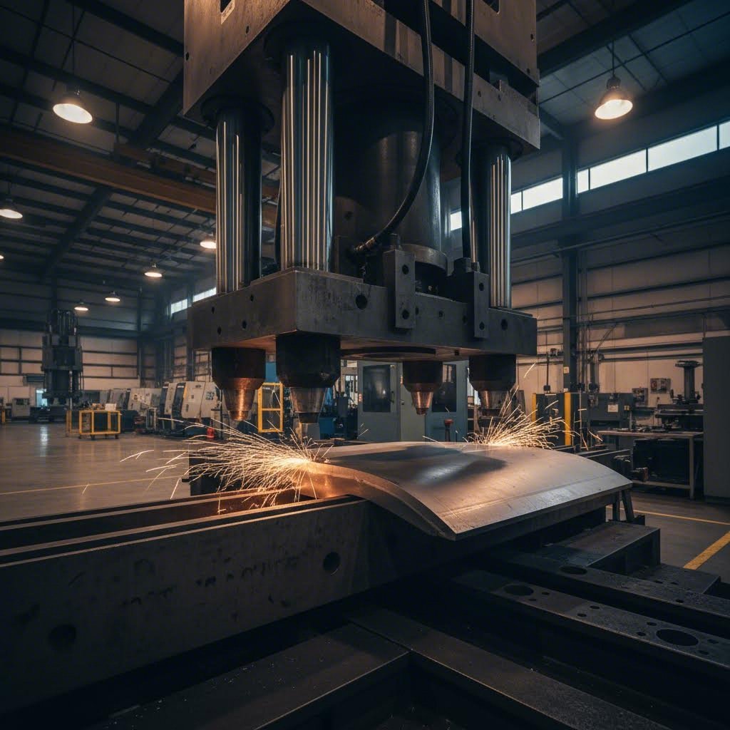
You've cut your aerospace alloy to precise dimensions. Now comes the transformation that separates airplane sheet metal from flat stock—forming operations that create the complex curves, compound contours, and aerodynamic surfaces essential for flight. Aviation sheet metal components rarely feature simple bends. Fuselage sections curve in multiple directions simultaneously, wing skins follow compound aerodynamic profiles, and engine components must withstand extreme forces while maintaining precise geometries.
How do manufacturers achieve these demanding shapes without compromising material integrity? The answer lies in specialized aerospace metal forming & bending techniques developed specifically for this industry's unique requirements.
Understanding Springback and Tooling Considerations
Before diving into specific forming methods, you'll need to understand a fundamental challenge that affects every bending operation: springback. When you bend metal, it doesn't stay exactly where you put it. The material's elastic properties cause it to partially return toward its original flat state once forming pressure releases.
Sounds complex? Imagine bending a paper clip. You push it past your target angle, knowing it will spring back slightly. Aerospace forming works the same way—but with tolerances measured in thousandths of an inch rather than eyeball estimates.
Springback compensation requires precise calculations based on material grade, thickness, bend radius, and forming temperature. Aluminum alloys like 2024-T3 exhibit different springback characteristics than titanium Ti-6Al-4V, and tooling must account for these variations. Modern aerospace fabricators use computer-simulated forming operations to predict springback and design compensating tool geometries before cutting expensive dies.
Tooling considerations extend beyond springback. Die materials must withstand repeated forming cycles without wear that could introduce dimensional variations. Surface finishes on tooling directly affect part surface quality—critical for aerodynamic surfaces where even minor imperfections increase drag. Tool heating and cooling systems maintain consistent temperatures throughout production runs, ensuring dimensional repeatability across hundreds or thousands of identical components.
Hydroforming and Stretch Forming for Aerodynamic Surfaces
When aerospace engineers need seamless fuselage sections or complex structural components, hydroforming delivers results that traditional stamping cannot match. According to Re:Build Cutting Dynamics' comprehensive hydroforming guide, this technique uses high-pressure hydraulic fluid to shape metals into precise, complex configurations—particularly beneficial in industries where strength-to-weight ratio is critical.
How does hydroforming work? The process places a metal blank into a specialized press where hydraulic fluid—acting through a rubber diaphragm—forces the sheet metal against a single rigid die. Unlike conventional stamping that requires expensive matched-metal die sets, hydroforming accomplishes complex shapes with only one die surface.
Key Advantages of Aerospace Hydroforming
- Wrinkle-free forming: The uniform fluid pressure eliminates wrinkles that plague conventional deep drawing operations
- Minimal material thinning: Well-designed hydroforming operations achieve thinning as low as 10%, preserving structural integrity
- Compound contours with varying bend angles: Sheet hydroforming excels at creating surfaces that curve in multiple directions simultaneously
- Reduced tooling costs: Single-die requirements significantly lower tooling investment compared to matched die sets
- High-mix, low-volume capability: Ideal for aerospace's production model of many different parts in smaller quantities
Applications range from structural components like fuselage frames and wing ribs to smaller intricate parts including ducts, brackets, and critical engine elements. Material selection remains crucial—aluminum and carbon steel are most commonly hydroformed, though expert facilities also process stainless steel and other aerospace-grade alloys.
Stretch Forming for Wing Skins and Large Panels
Stretch forming takes a different approach to creating curved aerospace surfaces. This process grips the sheet metal at both ends, stretches it beyond its yield point, and wraps it over a form die while maintaining tension. The stretching action work-hardens the material while eliminating springback issues that complicate conventional bending.
You'll find stretch forming applied to wing skins, large fuselage panels, and any component requiring smooth, consistent curves across extended surfaces. The technique produces exceptional surface finishes suitable for aerodynamic applications without the die marks or wrinkles that other methods might introduce.
Superplastic Forming for Complex Titanium Structures
What happens when aluminum and conventional forming techniques can't handle the heat or complexity your design demands? Superplastic forming (SPF) opens possibilities that seem almost impossible with standard metalworking.
According to research published in the Journal of Materials Research and Technology, superplasticity enables solid crystalline materials to achieve elongations of 700% and above without necking—far exceeding what conventional forming allows. This property enables production of components in a single step that would otherwise require combining multiple forming techniques with joining processes.
SPF works by heating fine-grain titanium alloys like Ti-6Al-4V to temperatures between 750-920°C where the material exhibits superplastic behavior. At these elevated temperatures and carefully controlled strain rates, the metal flows almost like thick honey, conforming precisely to die surfaces while maintaining uniform thickness.
Why Aerospace Manufacturers Choose Superplastic Forming
The advantages for aerospace applications are compelling. SPF produces complex shapes, patterns, and integrated structures that are lighter and stronger than conventionally formed and joined alternatives. According to the research review, the lower number of joints not only improves strength while maintaining lower weight but also enhances product performance and reduces overall manufacturing costs.
When combined with diffusion bonding, SPF enables multi-sheet structures and complicated assemblies that would require extensive welding or fastening with conventional approaches. The optimal grain size for SPF of Ti-6Al-4V was observed to be less than 3 micrometers—requiring careful material preparation before forming operations begin.
Chemical Milling for Weight Reduction
After forming operations complete, chemical milling often provides the final weight optimization step. This process selectively removes material from non-critical areas by masking protected zones and exposing the workpiece to controlled chemical etching.
Imagine a wing skin panel that needs to be thicker at attachment points but can be thinner across unsupported spans. Rather than machining away material mechanically, chemical milling etches precise pockets that reduce weight without introducing the stresses that mechanical cutting might cause. The process is particularly valuable for large panels where CNC machining would be prohibitively time-consuming.
Step-by-Step Aerospace Forming Operations
Understanding how these techniques integrate helps you appreciate the complexity of aerospace sheet metal fabrication. Here's how a typical forming operation progresses from raw material to precision component:
- Material preparation and inspection: Verify alloy certification, check for surface defects, and confirm material thickness meets specifications before forming begins
- Blank cutting: Laser, waterjet, or other cutting methods produce the flat blank with appropriate allowances for material flow during forming
- Blank conditioning: Heat treatment, surface preparation, or lubrication application as required by the specific forming process and material
- Tool setup and verification: Install forming dies, verify alignment and temperature controls, and confirm all parameters match the process specification
- Forming operation: Execute hydroforming, stretch forming, SPF, or other technique with controlled parameters throughout the cycle
- Initial inspection: Check formed geometry against specifications, verify no cracking or surface defects occurred during forming
- Secondary operations: Trimming, heat treatment, chemical milling, or surface finishing as required for the specific component
- Final inspection and documentation: Dimensional verification, surface quality assessment, and complete traceability documentation
Achieving Tight Tolerances Through Advanced Forming
How do these techniques deliver the precision aerospace demands? Several factors combine to achieve tolerances that often reach ±0.005 inches or tighter on formed components.
Hydroforming's uniform fluid pressure eliminates the inconsistencies inherent in matched die stamping, where slight variations in die alignment or press stroke affect part dimensions. The single rigid die approach ensures every part forms against the same reference surface.
Superplastic forming achieves exceptional dimensional control because the material flows uniformly at elevated temperatures, filling die cavities completely without the springback that plagues cold forming operations. The extended forming times—sometimes measured in hours rather than seconds—allow the material to fully conform to tooling surfaces.
Stretch forming eliminates springback by permanently deforming the material beyond its yield point. Since the entire sheet is under tension during forming, the resulting shape matches the tool geometry precisely without elastic recovery.
Quality assurance during forming extends beyond final inspection. Process monitoring tracks hydraulic pressure, temperature, forming speed, and other parameters in real-time, flagging any deviation that might affect part quality. This in-process control catches potential issues before they result in scrapped components.
With forming operations complete, the question becomes: how do you verify that these precision components actually meet aerospace specifications? The certification and quality standards covered next establish the framework that ensures every fabricated part delivers the performance aircraft safety demands.
Certifications and Quality Standards Explained
Your formed aerospace component looks perfect, but appearance alone doesn't guarantee airworthiness. Before any fabricated part can fly, it must pass through a rigorous certification framework that verifies every aspect of the manufacturing process meets aerospace industry standards. Understanding this certification hierarchy helps you navigate aerospace metal fabrication services requirements and evaluate potential suppliers.
Why do so many certifications exist? Each addresses different aspects of quality assurance, from overall management systems to highly specialized manufacturing processes. Together, they create interlocking verification layers that ensure aircraft components stamping and fabrication operations deliver consistently safe, reliable parts.
Navigating the Aerospace Certification Landscape
Three interconnected standards form the foundation of aerospace quality management: ISO 9001, AS9100, and NADCAP. Think of them as building blocks—each layer adds aerospace-specific requirements to the foundation below.
ISO 9001: The Universal Foundation
ISO 9001 establishes fundamental quality management principles applicable across all industries. It addresses organizational processes, documentation requirements, customer focus, and continuous improvement methodologies. However, according to industry certification experts, ISO 9001 alone is no longer deemed an acceptable prerequisite for aerospace accreditation—the industry demands more rigorous standards.
AS9100: The Aerospace Quality Standard
AS9100 builds upon ISO 9001 by adding over 100 aerospace-specific requirements. According to BPR Hub's aerospace quality analysis, AS9100 includes all ISO 9001:2015 quality management system requirements along with additional aviation, space, and defense industry requirements and definitions.
What makes AS9100 different from general quality standards? Key enhancements include:
- Risk management: Systematic identification, assessment, and mitigation of risks throughout the product lifecycle
- Configuration management: Precise control over design changes with complete traceability throughout the supply chain
- Project management: Structured oversight of complex aerospace manufacturing programs
- Counterfeit parts prevention: Verification systems ensuring material authenticity
- Human factors consideration: Processes addressing error prevention and workforce competency
AS9100D certification—the current revision—typically takes 6-18 months to achieve, depending on organizational complexity and existing quality system maturity. As noted by Nediar's supply chain analysis, suppliers with AS9100D certification demonstrate their commitment to aerospace excellence, ensuring they meet the highest expectations of OEMs and Tier 1 clients.
Related AS91XX Standards
The AS9100 family includes specialized variants for specific aerospace operations:
- AS9120: Quality management systems for stockist and pass-through distributors handling aerospace materials
- AS9110: Requirements specific to maintenance organizations servicing commercial, private, and military aircraft
NADCAP Special Process Accreditation Requirements
While AS9100 addresses overall quality management systems, NADCAP (National Aerospace and Defense Contractors Accreditation Program) provides specialized accreditation for critical manufacturing processes. Established by the Performance Review Institute in 1990, NADCAP eliminates redundant supplier audits by creating industry-agreed standards for special processes.
Before NADCAP existed, aerospace companies individually audited their suppliers to verify process compliance. The result? Duplicate audits that proved redundant and created workload without adding value. OEMs recognized that failed components often trace back to flawed supplier processes, making standardized audits both necessary and desirable.
Special Processes Covered by NADCAP
NADCAP accreditation encompasses 17 main process groups, each led by a Task Group comprising prime contractors, government representatives, and suppliers. For sheet metal fabrication, the most relevant categories include:
- Heat treating
- Chemical processing and coatings
- Welding
- Non-destructive testing
- Materials testing laboratories
- Measurement and inspection
According to the complete NADCAP guide, achieving NADCAP accreditation demonstrates a supplier's commitment to maintaining the highest quality standards—industry-consensus verified—confirming that operations follow recognized best practices.
The NADCAP Audit Process
NADCAP audits follow a structured process:
- Internal audit: Complete self-assessment against applicable NADCAP checklists, submitted at least 30 days before the formal audit
- Audit scheduling: Request audit through eAuditNet and receive PRI-assigned industry-approved auditors
- On-site audit: Two to five day evaluation including process reviews, employee interviews, and job tracing from contract review through shipping
- Non-conformance resolution: Address any findings with five-part corrective action including containment, root cause, permanent correction, verification, and recurrence prevention
- Task Group review: Subscribing primes review the completed audit package and vote on acceptability
- Accreditation: Granted once all non-conformances are closed and Task Group approves
Initial NADCAP accreditation runs on a 12-month cycle. Subsequent accreditation periods extend to 18 or 24 months based on demonstrated performance excellence.
Certification Requirements by Supplier Tier
Not every aerospace supplier needs identical certifications. Requirements scale based on your position in the supply chain and the processes you perform.
| Certification | Scope | OEMs | Tier 1 | Tier 2 | Tier 3 |
|---|---|---|---|---|---|
| AS9100D | Comprehensive quality management system for aerospace manufacturing | Required | Required | Typically Required | Often Required |
| NADCAP | Special process accreditation (heat treat, NDT, chemical processing, etc.) | Required for applicable processes | Required by most OEMs | Required when performing special processes | May be required for specific processes |
| ISO 9001 | General quality management foundation | Superseded by AS9100 | Superseded by AS9100 | Insufficient alone | Insufficient alone |
| ITAR Registration | U.S. defense article manufacturing and export compliance | Required for defense work | Required for defense work | Required for defense work | Required for defense work |
ITAR Compliance for Defense Applications
Defense aerospace fabrication introduces additional regulatory requirements. The International Traffic in Arms Regulations (ITAR) controls the manufacturing, sale, and distribution of defense-related technology. Any supplier handling ITAR-controlled work must maintain appropriate registration and compliance programs.
NADCAP builds ITAR safeguards directly into its audit process. Some auditors have restricted export control status, meaning they cannot perform audits for ITAR/EAR-restricted work. Suppliers must disclose whether work falls under ITAR/EAR guidelines when scheduling audits to avoid rescheduling and associated fees.
Automotive Quality Systems and Aerospace Applications
Interestingly, quality certifications from other demanding industries can demonstrate transferable capabilities. IATF 16949—the automotive industry's quality management standard—shares foundational principles with AS9100, including risk-based thinking, traceability requirements, and rigorous process control.
Manufacturers holding IATF 16949 certification have already proven their ability to implement robust quality management systems for safety-critical components. While IATF 16949 doesn't substitute for AS9100 in aerospace applications, it demonstrates quality management maturity that supports aerospace certification efforts. Precision stamping operations meeting automotive tolerances often translate directly to aerospace structural component requirements.
The certification framework ensures consistent quality across the aerospace supply chain. However, certifications address systems and processes—the next critical element involves verifying that individual components actually meet specifications through rigorous quality control and inspection requirements.
Quality Control and Precision Inspection Requirements
Your aerospace component has passed through cutting, forming, and finishing operations. It looks flawless to the naked eye. But here's the reality: visual appearance tells you almost nothing about whether that part will perform safely at 35,000 feet. Hidden cracks, subsurface voids, and dimensional variations measured in thousandths of an inch can mean the difference between a component that flies for decades and one that fails catastrophically.
How do aerospace manufacturers verify what they cannot see? The answer lies in sophisticated aerospace quality control inspection protocols that examine every critical component without damaging it—and documentation systems that trace every part's complete history from raw alloy to flight-ready installation.
Non-Destructive Testing Methods for Critical Components
Non-destructive testing (NDT) forms the backbone of aerospace quality verification. As Aerospace Testing International reports, NDT technology has become increasingly important in the aerospace sector, with companies viewing it as a key element of testing in development, manufacturing, maintenance, and inspection processes.
But which NDT method works best for your component? The answer depends on material type, defect characteristics, part geometry, and where that component sits in its lifecycle. Let's examine the primary techniques used in NDT testing aerospace components.
Penetrant Testing for Surface Defects
Penetrant testing (PT) reveals surface-breaking cracks and porosity that visual inspection might miss. The process applies a colored or fluorescent liquid that seeps into any surface discontinuities. After removing excess penetrant, a developer draws the trapped liquid back to the surface, making defects visible under appropriate lighting.
You'll find penetrant testing widely applied to aluminum and titanium aerospace components. According to industry experts, PT ranks among the most commonly used NDT methods for manufacturing metallic parts. Its simplicity and effectiveness make it ideal for detecting fatigue cracks, grinding marks, and surface porosity on formed sheet metal components.
Ultrasonic Testing for Internal Flaws
When defects hide beneath the surface, ultrasonic testing (UT) provides the answers. This technique transmits high-frequency sound waves through the material—any internal discontinuity reflects the waves back to the transducer, revealing its location and size.
Modern Phased Array Ultrasonic Testing (PAUT) has revolutionized aerospace inspection capabilities. As noted by Waygate Technologies, PAUT facilitates inspection of large-scale composite materials with complex internal structures, providing detailed internal images that allow inspectors to locate and characterize defects with precision.
UT excels at detecting delaminations, inclusions, and voids in both metallic and composite aerospace structures. The technology also measures material thickness—critical for components that have undergone chemical milling or may have experienced corrosion during service.
Radiographic Testing and Computed Tomography
Radiographic testing (RT) uses X-rays or gamma rays to create images of a component's internal structure. Think of it as a medical X-ray for aerospace parts—denser areas appear lighter on the resulting image, revealing internal defects, porosity, and inclusions.
Digital radiography has significantly impacted aerospace inspection. According to industry sources, digital radiography offers major cost savings in consumable materials and waste disposal while enabling more detailed image evaluation for accurate reporting. For complex components like turbine blades, computed tomography (CT) creates three-dimensional models that reveal internal geometries impossible to inspect otherwise.
High-energy CT systems have become essential for inspecting large, dense aerospace components. These systems use linear accelerators to generate penetrating X-rays capable of examining samples that traditional methods could not adequately inspect.
Magnetic Particle and Eddy Current Testing
Magnetic particle testing (MT) detects surface and near-surface defects in ferromagnetic materials. The process magnetizes the component and applies iron particles that cluster around any discontinuities, creating visible indications. While limited to ferrous metals, MT provides rapid, sensitive detection of cracks in steel aerospace components.
Eddy current testing (ET) uses electromagnetic induction to detect surface and near-surface flaws in conductive materials. An electromagnetically charged probe induces eddy currents in the test material—any defects disturb these currents, generating detectable signals. ET proves particularly valuable for maintenance inspection of metallic aircraft structures and for detecting cracks around fastener holes.
Selecting the Right NDT Method
Which technique should you specify? Methods are chosen depending on specific design requirements, material type, product topography, and whether the inspection occurs during production or in-field maintenance. Often, multiple methods complement each other—penetrant testing might screen for surface defects before ultrasonic testing examines internal integrity.
- Aluminum sheet metal components: Penetrant testing for surface cracks, ultrasonic testing for internal flaws, eddy current for fatigue crack detection
- Titanium engine components: Ultrasonic testing for subsurface defects, penetrant testing for surface discontinuities
- Ferromagnetic steel parts: Magnetic particle testing for surface and near-surface defects
- Complex internal geometries: Computed tomography for complete volumetric inspection
- Composite structures: Ultrasonic testing and infrared thermography for delamination detection
Dimensional Inspection and Precision Measurement
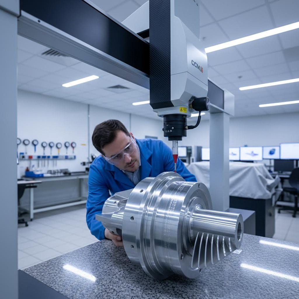
NDT verifies material integrity, but dimensional inspection confirms that your component matches design specifications. For aerospace applications, this means measuring features to tolerances that often reach ±0.001 inches or tighter. According to industry precision forming specialists, manufacturers regularly work to tolerances as tight as ±0.001 inches, particularly for aerospace brackets and defense-critical parts.
How do you verify such precise dimensions? Modern aerospace fabricators employ coordinate measuring machines (CMMs), laser micrometers, and optical comparators to inspect features in real time as parts are formed. These systems verify dimensional accuracy, part geometry, and alignment without halting production.
Surface finish and flatness inspections prove equally critical. Profilometry tests measure surface roughness while flatness gauges ensure parts meet required tolerances—particularly important for mating surfaces and components requiring aerodynamic smoothness.
Traceability Documentation Requirements
Aerospace traceability requirements extend far beyond simple quality records. Every component must carry complete documentation linking it back through every processing step to the original raw material certification. Why does this matter so much? As industry traceability experts explain, traceability is the ability to track an aircraft part's complete history—from its original manufacturer, through every owner and installation, to its current status.
This comprehensive documentation serves multiple purposes. When issues arise, traceability enables rapid identification of affected components across the entire fleet. It also prevents counterfeit or unapproved parts from entering aircraft—a growing concern that prompted formation of the Aviation Supply Chain Integrity Coalition in 2024.
Essential Quality Documentation
What documentation must accompany aerospace fabricated components? The requirements create a complete paper trail verifiable at any point:
- Material certifications: Original mill test reports verifying alloy composition, heat treatment, and mechanical properties
- Process records: Documentation of every manufacturing operation including cutting parameters, forming specifications, and heat treatment cycles
- Inspection records: Complete NDT and dimensional inspection results with inspector certifications
- Authorized Release Certificates: FAA Form 8130-3 (U.S.) or EASA Form 1 (EU) demonstrating airworthiness approval
- Lot and serial number tracking: Unique identifiers linking each component to its complete manufacturing history
- Calibration records: Verification that all measuring and test equipment used during fabrication maintained proper calibration
- Personnel certifications: Documentation confirming that operators and inspectors held appropriate qualifications for their roles
Every part should have a paper trail—increasingly digital—that's clear, verifiable, and accessible when needed. Modern aerospace manufacturers use cloud-based systems and digital record-keeping to maintain this documentation, enabling rapid retrieval during audits or incident investigations.
The Cost of Non-Compliance
What happens when quality control fails? The implications of non-compliance can include structure failures, which can be dramatic. Beyond catastrophic safety risks, quality failures result in additional work to correct non-conformances, operator retraining, procedural amendments, or worst case, suspension of manufacturing processes.
Human factors remain the biggest source of mistakes in the industry. As experienced NDT professionals advise, sticking to technical procedures is extremely important—when something doesn't seem right, stop, raise a hand, talk to your supervisor, and find a solution before proceeding.
Looking ahead, artificial intelligence and machine learning are poised to transform aerospace quality control. AI-enabled analytics can automatically recognize and categorize defects, improving data quality while streamlining critical inspections. These technologies relieve inspectors of routine tasks, giving them time to focus on important details that require human judgment.
With quality control systems ensuring component integrity, the next consideration becomes development timelines and cost factors. Understanding how prototyping differs from production—and what drives aerospace fabrication costs—helps you plan projects effectively from concept through full-scale manufacturing.
Prototyping and Cost Considerations for Aerospace Projects
You've mastered the materials, cutting methods, forming techniques, and quality requirements for aerospace sheet metal fabrication. But here's a question that catches many project managers off guard: why does a single prototype part sometimes cost more than dozens of production units? Understanding the unique economics of aircraft prototype development—and the factors driving aerospace manufacturing pricing—helps you budget accurately and avoid costly surprises.
Aerospace rapid prototyping services operate under constraints that simply don't exist in other industries. Every prototype must demonstrate the same material integrity, dimensional precision, and documentation rigor as production parts—even when you're only making one.
Accelerating Development Cycles with Rapid Prototyping
Rapid prototyping in aerospace isn't just about speed—it's about making smarter decisions early. According to 3ERP's industry analysis, this "fail-fast" approach is key to catching design issues early, which can save up to 20% off production costs by identifying problems before they become embedded in tooling and processes.
But don't let the term "rapid" mislead you. Despite accelerated techniques, turning a new concept into a fully tested aerospace prototype can still take a couple of months. Why so long when consumer product prototypes might appear in days?
Material Certification Challenges
Imagine you need a prototype bracket from Ti-6Al-4V titanium. You can't simply order material from any supplier. The titanium must come with complete mill certifications verifying composition, mechanical properties, and processing history. Finding certified material in prototype quantities—rather than production volumes—often proves difficult and expensive.
As RCO Engineering notes, fluctuations in material availability, certification delays, or changes in supplier capabilities can quickly derail a prototyping timeline. Manufacturers must not only innovate with cutting-edge materials but also strategically manage sourcing, testing, and certification to maintain project momentum.
Testing Requirements That Mirror Production
Your prototype faces the same NDT inspections, dimensional verification, and documentation requirements as production components. There's no "prototype exception" for safety-critical aerospace parts. This means:
- Complete penetrant or ultrasonic testing to verify material integrity
- CMM inspection confirming dimensions meet drawing specifications
- Full traceability documentation from raw material through final inspection
- First Article Inspection reports demonstrating process capability
These requirements add time and cost that simply don't exist in non-aerospace prototyping scenarios.
Design Iteration Under Regulatory Constraints
Aerospace prototyping involves navigating an intricate web of specifications, tolerances, and functional requirements. Even the slightest design flaw can compromise the entire system, leading to costly delays or rework. Multiple rounds of design iteration, combined with rigorous virtual and physical testing, are now standard practice to de-risk projects before full-scale production begins.
Today's aerospace clients demand faster turnarounds, custom configurations, and integrated solutions—all while maintaining uncompromising safety standards. This tension between speed and compliance defines the aerospace prototyping challenge.
Bridging Prototype to Production in Aerospace
The transition from prototype to production represents another unique aerospace challenge. Unlike industries where prototypes serve primarily as proof-of-concept models, aerospace prototypes must demonstrate manufacturing repeatability and process stability.
According to industry research, successful prototyping requires seamless collaboration between design engineers, materials specialists, manufacturing technicians, and quality assurance teams. Each group must iterate rapidly, relying on real-time data from simulations, testing, and supplier feedback to ensure prototypes meet the standards expected in aerospace manufacturing.
Production Readiness Considerations
Before scaling from prototype to production, manufacturers must verify:
- Process repeatability: Can the forming, cutting, and finishing operations produce consistent results across hundreds or thousands of parts?
- Tooling durability: Will dies and fixtures maintain dimensional accuracy through production volumes?
- Supply chain stability: Are certified materials available in production quantities with reliable lead times?
- Inspection efficiency: Can quality verification keep pace with production rates without compromising thoroughness?
These questions often reveal gaps between prototype success and production viability—gaps that require additional development time and investment to close.
Understanding Aerospace Fabrication Cost Factors
Managing costs is a constant concern during aerospace prototyping, where precision, safety, and innovation are paramount. The specialized materials, advanced technologies, and skilled labor required produce substantial expenses that exceed general industrial fabrication by significant margins.
What drives aerospace manufacturing pricing so much higher than conventional sheet metal work? The answer involves multiple interconnected factors:
Key Cost Drivers in Aerospace Fabrication Projects
- Material costs: Aerospace-grade alloys cost significantly more than commercial equivalents. Titanium Ti-6Al-4V and Inconel 718 command premium prices, while even certified aluminum alloys carry cost premiums over standard grades. Material waste from precision cutting operations compounds these expenses.
- Certification overhead: Maintaining AS9100D certification, NADCAP accreditations, and ITAR compliance requires dedicated quality personnel, regular audits, and continuous training. These fixed costs spread across every project.
- Inspection requirements: NDT testing, dimensional verification, and documentation consume substantial labor hours. A component requiring ultrasonic testing, penetrant inspection, and CMM verification may spend more time in quality than in fabrication.
- Specialized tooling: Aerospace forming operations require precision dies and fixtures that often cost tens of thousands of dollars. For prototype quantities, this tooling investment spreads across very few parts.
- Skilled labor: Certified welders, NDT technicians, and precision machinists command premium wages. Their expertise cannot be replaced with automation for complex aerospace work.
- Documentation and traceability: Creating complete paper trails for every component requires administrative time that adds no physical value to the part but remains essential for airworthiness.
- Low-volume inefficiency: Setup times for precision operations remain constant whether you're making one part or one hundred. Prototype runs absorb full setup costs across minimal production quantities.
- Engineering support: DFM reviews, process development, and first-article qualification require engineering hours that don't recur in steady-state production.
Balancing Cost and Quality
These financial pressures compound broader aerospace engineering challenges, as manufacturers must find ways to innovate without exceeding budget limitations. Strategic planning, efficient resource allocation, and early-stage risk mitigation keep prototype projects financially viable while meeting the high standards expected in the aerospace industry.
Accelerated timelines add another dimension to cost management. Companies must balance the need for rapid development with uncompromising standards of quality, performance, and safety. Shortened development cycles can strain internal resources and magnify supply chain challenges such as material shortages and lead time delays.
Understanding these cost dynamics helps you evaluate aerospace fabrication partner capabilities realistically. The next section examines how to assess potential suppliers and navigate the complex aerospace supply chain relationships that determine project success.

Aerospace Supply Chain and Partner Selection
You've developed a promising aerospace component design and understand the materials, fabrication techniques, and quality requirements involved. Now comes a critical question: who actually manufactures your parts? Navigating aerospace supply chain management requires understanding how sheet metal fabrication fits within the industry's complex network of OEMs, tiered suppliers, and specialized process providers.
Selecting the right aerospace fabrication partner selection can determine whether your project succeeds or stumbles. The wrong choice leads to missed deadlines, quality escapes, and certification headaches. The right partner becomes an extension of your engineering team—contributing expertise that strengthens your final product.
Understanding OEM and Tiered Supplier Relationships
How does your fabricated sheet metal component reach the aircraft? The aerospace industry operates through a structured supply chain where responsibilities cascade from major manufacturers down through multiple supplier tiers.
According to Nediar's aerospace supply chain analysis, OEMs (Original Equipment Manufacturers) like Boeing, Airbus, Lockheed Martin, and Bombardier design, develop, and manufacture complete aircraft or major systems. These companies set design specifications and manage large portions of the aircraft lifecycle—from concept through after-sales support. However, OEMs don't fabricate every component themselves. They rely heavily on a multi-tier supply chain to manufacture and integrate thousands of parts.
Tier 1 Suppliers
Tier 1 suppliers work directly with OEMs, delivering complete systems such as avionics, propulsion units, landing gears, or flight control systems. Companies like Safran, Honeywell, and Collins Aerospace operate at this level. These suppliers must meet the highest standards in engineering, quality, and regulatory compliance—often maintaining their own extensive supplier networks.
Tier 2 Suppliers
Tier 2 suppliers provide major subassemblies, precision components, or specialized tooling to Tier 1 suppliers. This tier includes sheet metal fabricators producing structural brackets, ducts, panels, and complex formed components. According to industry analysis, Tier 2 suppliers handle everything from precision sheet metal parts to electronic systems and simulation hardware.
Tier 3 Suppliers
Tier 3 suppliers manufacture basic parts, raw materials, or simple machined components used by Tier 2 or Tier 1 suppliers in more complex assemblies. Although positioned deeper in the supply chain, these suppliers must still comply with strict quality and traceability requirements. A surface treatment provider, fastener manufacturer, or raw material distributor typically operates at this tier.
Where Sheet Metal Fabrication Fits
Sheet metal fabrication operations typically fall within Tier 2 or Tier 3 depending on component complexity and the fabricator's capabilities. A company producing complete structural subassemblies with integrated fastening and surface treatment operates as Tier 2. A fabricator supplying cut-and-formed blanks for further assembly by others functions as Tier 3.
Understanding your supplier's position helps you evaluate their capabilities realistically. A Tier 3 supplier may offer competitive pricing for straightforward components but lack the systems integration experience that complex assemblies demand.
Evaluating Aerospace Fabrication Partners
What separates a capable aerospace fabrication partner from one that will create headaches? According to BOEN Rapid's supplier evaluation guide, technical expertise and manufacturing capabilities stand at the forefront of consideration. But evaluation extends far beyond checking equipment lists.
The best supplier relationships are built on mutual trust, open communication, and shared commitment to excellence. Finding that partner requires systematic evaluation across multiple dimensions.
Questions to Ask Potential Suppliers
Before requesting quotes, gather information that reveals a supplier's true capabilities:
- Certification status: Which aerospace certifications do you hold? Are AS9100D and relevant NADCAP accreditations current?
- Material experience: What aerospace alloys have you processed? Can you provide examples of similar components?
- Quality systems: What NDT methods do you perform in-house? How do you handle dimensional inspection and documentation?
- Capacity and flexibility: Can you handle our prototype quantities? What's your typical lead time for first articles? How quickly can you scale to production volumes?
- Supply chain management: How do you source certified aerospace materials? What contingency plans exist for supply disruptions?
- Technical support: Do you offer DFM (Design for Manufacturability) reviews? How do you handle engineering changes during production?
- Financial stability: How long have you operated in aerospace? Who are your major customers?
The answers reveal not just what a supplier can do, but how they approach challenges and whether their culture aligns with your project needs.
Essential Evaluation Criteria
When selecting an aerospace fabrication partner, work through this structured evaluation to ensure comprehensive assessment:
- Verify certifications and accreditations: Confirm AS9100D certification is current and covers the processes your components require. Check NADCAP accreditations for special processes like heat treatment, welding, or NDT. For defense work, verify ITAR registration and compliance programs.
- Assess technical capabilities: Evaluate equipment lists against your component requirements. Confirm the supplier has experience with your specific alloys and geometries. Request case studies or examples of similar aerospace work.
- Evaluate quality management systems: Review their quality manual and inspection procedures. Understand how they maintain traceability from raw material through shipping. Ask about their defect rates and corrective action processes.
- Examine production capacity and flexibility: Determine whether they can handle your volumes—both prototype and production. Assess their ability to scale up without compromising quality. Understand their approach to capacity planning and resource allocation.
- Review supply chain resilience: Investigate their material sourcing strategies and backup suppliers. Ask about inventory management for critical materials. Understand their approach to mitigating supply disruptions.
- Assess communication and responsiveness: Evaluate response times during the quoting process—they often predict ongoing communication quality. Confirm they have technical staff available to support engineering questions. Look for secure project management portals and documentation systems.
- Check track record and references: Request references from other aerospace customers. Look for long-term relationships with major aerospace manufacturers. Investigate their reputation within industry associations.
- Evaluate financial stability: Review available financial information or credit reports. Consider business diversification—suppliers serving multiple industries often weather sector downturns better. Assess their investment in new capabilities and continuous improvement.
The Value of Transferable Quality Systems
Interestingly, precision metal fabrication expertise from adjacent industries can support aerospace supply chain needs. Manufacturers with IATF 16949 certification and precision stamping capabilities—like those serving automotive chassis and structural component requirements—demonstrate quality management maturity that translates to aerospace applications.
Both automotive and aerospace demand rigorous process control, complete traceability, and zero-defect quality cultures. A supplier delivering precision stamping for automotive suspension components already understands the documentation requirements, dimensional tolerances, and material verification that aerospace programs require. While AS9100D certification remains necessary for aerospace work, IATF 16949-certified suppliers often achieve aerospace certification more efficiently because their quality systems already incorporate similar rigor.
According to QSTRAT's supplier qualification analysis, the aerospace industry increasingly uses performance scorecards that allocate points across weighted criteria—typically quality performance (35%), delivery performance (25%), technical capability (20%), and commercial factors (20%). Suppliers demonstrating strong performance in demanding industries like automotive often score well on these metrics from day one.
Building Long-Term Partnerships
The best aerospace fabrication relationships extend beyond transactional purchasing. As industry experts note, suppliers who demonstrate a forward-thinking approach and willingness to push boundaries of conventional manufacturing become valuable long-term partners in driving innovation and efficiency.
Look for suppliers who invest in continuous improvement, employee training, and technology upgrades. Their commitment to advancement benefits your programs as their capabilities grow. Collaborative relationships where suppliers contribute DFM insights and process innovations create value that transcends component pricing.
With supply chain relationships established and partner capabilities verified, the final consideration involves understanding how requirements differ across aerospace sectors—and how to troubleshoot common fabrication challenges when they arise.
Sector-Specific Applications and Problem Solving
Not all aerospace is created equal. A fuselage panel destined for a commercial airliner faces different demands than a component bound for a military fighter jet or a satellite heading into orbit. Understanding how commercial aviation fabrication requirements, defense aerospace manufacturing, and space industry metal fabrication differ helps you tailor specifications, select appropriate suppliers, and anticipate sector-specific challenges before they derail your project.
Beyond sector differences, every fabrication operation encounters technical hurdles. Springback that throws dimensions off target, material distortion that warps precision surfaces, surface finish requirements that push processing limits—these challenges appear across all aerospace sectors. Knowing how to troubleshoot them separates successful programs from costly failures.
Commercial Aviation vs. Defense and Space Requirements
Each aerospace sector operates under distinct regulatory frameworks, performance expectations, and operational environments. What works perfectly for a commercial passenger jet may prove inadequate for a hypersonic missile or completely unsuitable for a deep-space probe.
Commercial Aviation Priorities
Commercial aviation emphasizes passenger safety, fuel efficiency, and long-term durability across tens of thousands of flight cycles. Components must withstand repeated pressurization, temperature fluctuations between ground and cruising altitude, and constant vibration—all while remaining lightweight enough to minimize fuel consumption.
FAA and EASA certification requirements drive commercial aviation fabrication. Parts must demonstrate compliance with airworthiness standards through extensive documentation and testing. Production volumes tend to be higher than defense or space applications, enabling economies of scale but demanding consistent quality across thousands of identical components.
Defense Aerospace Demands
Defense aerospace manufacturing adds survivability, ruggedness, and performance under extreme conditions to the equation. Military aircraft experience combat stresses, electromagnetic interference, and environmental extremes that exceed standard commercial requirements. According to YICHOU's aerospace materials analysis, defense applications demand tactical UAV components, armored aircraft parts, and structures designed to perform reliably in hostile environments.
MIL-SPEC requirements govern defense fabrication, often specifying tighter tolerances and more rigorous testing than commercial equivalents. ITAR compliance adds administrative complexity for any supplier handling defense-related work. Production volumes typically fall between commercial and space applications—enough for fleet requirements but rarely approaching commercial airline quantities.
Space Industry Extremes
Space industry metal fabrication pushes materials and processes to absolute limits. Components face vacuum conditions, radiation exposure, extreme temperature swings, and the violent forces of launch—often with zero opportunity for maintenance or repair once deployed.
As noted in aerospace materials research, space-grade materials like titanium, Inconel, and carbon composites must withstand temperatures up to 1000°C in some applications while maintaining structural integrity. Thermal insulation materials including reinforced carbon-carbon and multi-layer insulation protect components during re-entry or extended space exposure.
Production volumes for space applications are typically very low—sometimes single units—making every component essentially a custom fabrication. The cost tolerance is higher given mission criticality, but quality expectations are absolute.
Comparing Sector Requirements
| Requirement | Commercial Aviation | Defense Aerospace | Space Applications |
|---|---|---|---|
| Primary Regulatory Framework | FAA/EASA airworthiness standards | MIL-SPEC, ITAR compliance | NASA standards, mission-specific requirements |
| Typical Production Volume | High (fleet quantities) | Medium (military fleet needs) | Very low (often single units) |
| Temperature Extremes | -60°F to 300°F typical | Similar to commercial plus combat conditions | -250°F to 2000°F+ depending on application |
| Primary Material Focus | Aluminum alloys (2024, 7075), some titanium | Titanium, high-strength steel, radar-absorbing materials | Titanium, Inconel, specialized composites, exotic alloys |
| Service Life Expectation | 20-30 years, thousands of cycles | Variable based on platform, high utilization | Mission duration (months to decades), no maintenance |
| Cost Sensitivity | High (competitive airline economics) | Moderate (budget-driven but performance-critical) | Lower (mission success paramount) |
| Quality Documentation | Comprehensive, FAA Form 8130-3 | Comprehensive plus security requirements | Extreme documentation, full traceability |
| Unique Challenges | Fatigue resistance, corrosion prevention | Survivability, stealth characteristics, rapid repair | Vacuum compatibility, radiation resistance, weight optimization |
Overcoming Common Fabrication Challenges
Regardless of which sector your components serve, certain fabrication challenges appear consistently. Understanding aerospace fabrication troubleshooting techniques helps you specify requirements correctly, evaluate supplier capabilities, and resolve issues when they arise.
Springback Compensation
Springback—the tendency of formed metal to partially return toward its original flat state—plagues every bending operation. The material's elastic properties cause this recovery, and the effect varies with alloy type, thickness, bend radius, and grain direction.
Solutions for springback control:
- Overbending: Form the material past the target angle by a calculated amount, allowing springback to bring it to the correct final position
- Bottom bending: Use sufficient tonnage to fully coin the bend, permanently setting the material at the desired angle
- Stretch forming: Apply tension during forming to exceed the material's yield point, eliminating elastic recovery
- Hot forming: Elevate material temperature to reduce yield strength and minimize springback effects
- Simulation and testing: Use finite element analysis to predict springback before cutting expensive production tooling
Different alloys exhibit different springback characteristics. High-strength aluminum 7075-T6 springs back more aggressively than 2024-T3, requiring larger compensation factors. Titanium alloys demand even more aggressive overbending or hot forming techniques.
Material Distortion Control
Distortion during cutting, forming, or heat treatment can render precision aerospace components unusable. Residual stresses locked in the material during rolling or previous processing release during fabrication, causing warping, twisting, or dimensional changes.
Strategies for minimizing distortion:
- Stress-relieved material: Specify stress-relieved tempers when dimensional stability is critical
- Symmetric machining: Remove material equally from both sides to maintain stress balance
- Incremental processing: Break heavy cuts or forms into multiple lighter passes, allowing stress redistribution between operations
- Fixture design: Use fixtures that support the workpiece properly without introducing additional stresses
- Cold-working alternatives: Consider waterjet cutting over thermal methods to avoid heat-induced distortion in sensitive materials
- Post-process stress relief: Apply controlled heat treatment cycles to stabilize components before final machining
According to surface finishing specialists, waviness—defined as periodic variations in surface finish resulting from machining flaws and warping from heat and cold—represents one manifestation of distortion that affects component performance.
Surface Finish Requirements
Aerospace components demand specific surface finishes for aerodynamic performance, fatigue resistance, and coating adhesion. Meeting required Ra values while achieving correct lay patterns requires careful process selection and control.
Addressing surface finish challenges:
- Tool selection: Choose cutting tools and abrasives appropriate for the target finish—finer isn't always better if it slows production unnecessarily
- Lay pattern control: Many aerospace parts require circular lay patterns for surfaces where adhesion is important or fluid must flow in specific directions
- Automated finishing: As noted by Xebec Deburring Solutions, automated deburring and finishing tools can achieve required Ra values before parts leave the machine, eliminating post-machining manual processes
- Process sequencing: Plan operations so that finishing occurs after heat treatment and other processes that might degrade surface quality
- Measurement verification: Use profilometry to verify surface roughness meets specifications before components proceed to subsequent operations
For most aerospace parts, meeting a surface roughness of 8 Ra represents the standard requirement. Modern automated finishing tools often achieve this without separate polishing operations, saving significant time and cost while improving consistency over manual methods.
Common Issues and Quick Reference Solutions
- Cracking during forming: Reduce bend radius, anneal material before forming, or consider superplastic forming for complex shapes
- Inconsistent dimensions across production runs: Verify tooling wear, confirm material lot consistency, and check for temperature variations in the forming environment
- Surface contamination: Implement proper handling procedures, verify cleaning process effectiveness, and control shop environment
- Weld distortion: Use fixture restraint, balanced welding sequences, and appropriate heat input control
- Coating adhesion failures: Verify surface preparation meets coating manufacturer requirements and confirm surface cleanliness before application
The Future of Aerospace Sheet Metal Fabrication
While the fundamental physics of forming metal haven't changed, the technologies enabling aerospace fabrication continue evolving. Advanced simulation tools predict forming behavior with increasing accuracy, reducing trial-and-error tooling iterations. Automated inspection systems catch defects faster and more consistently than human inspectors alone.
The integration of additive manufacturing with traditional sheet metal processes opens new possibilities for hybrid components that combine the design freedom of 3D printing with the proven performance of formed aerospace alloys. Meanwhile, new aluminum-lithium alloys and advanced composites continue pushing the boundaries of strength-to-weight performance.
What remains constant? The uncompromising demand for precision, documentation, and quality that defines aerospace manufacturing. Whether your component flies on a commercial airliner, a military fighter, or a spacecraft bound for distant planets, the same fundamental principles apply: select the right materials, apply appropriate fabrication techniques, verify quality thoroughly, and document everything. Master these elements, and you'll deliver sheet metal components that meet the demanding standards aerospace applications require.
Frequently Asked Questions About Aerospace Sheet Metal Fabrication
1. What materials are commonly used in aerospace sheet metal fabrication?
Aerospace sheet metal fabrication primarily uses aluminum alloys (2024-T3 for fuselage panels with excellent fatigue resistance, 7075-T6 for high-strength structural brackets), titanium Ti-6Al-4V for engine components operating up to 600°C, and nickel superalloys like Inconel 718 for extreme-temperature applications reaching 982°C. Material selection depends on strength-to-weight ratio requirements, temperature tolerance, corrosion resistance, and specific component applications within the aircraft structure.
2. What certifications are required for aerospace sheet metal fabrication?
Essential certifications include AS9100D (the comprehensive aerospace quality management standard with 100+ requirements beyond ISO 9001), NADCAP accreditation for special processes like heat treatment, welding, and NDT, and ITAR registration for defense-related work. Certification requirements vary by supplier tier—OEMs and Tier 1 suppliers require full certification suites, while Tier 2 and 3 suppliers need certifications matching their specific manufacturing processes. Manufacturers with IATF 16949 automotive certification often demonstrate transferable quality systems that support aerospace certification efforts.
3. What are the main aerospace sheet metal fabrication techniques?
Key techniques include precision cutting (laser cutting for thin aluminum panels, waterjet for heat-sensitive titanium with zero HAZ, EDM for intricate engine components), advanced forming (hydroforming for seamless fuselage sections, stretch forming for wing skins, superplastic forming for complex titanium structures achieving 700%+ elongation), and chemical milling for weight reduction. Each method addresses specific material properties and tolerance requirements, with aerospace components often requiring ±0.001 inch precision.
4. How does quality control work in aerospace fabrication?
Aerospace quality control employs multiple non-destructive testing methods: penetrant testing for surface defects, ultrasonic testing for internal flaws, radiographic/CT scanning for complex geometries, and magnetic particle or eddy current testing for specific materials. Dimensional inspection uses CMMs and laser micrometers to verify tolerances as tight as ±0.001 inches. Complete traceability documentation links every component from raw material certification through final inspection, including process records, NDT results, and Authorized Release Certificates.
5. What factors affect aerospace sheet metal fabrication costs?
Major cost drivers include aerospace-grade material premiums (titanium and Inconel cost significantly more than standard alloys), certification overhead (AS9100D, NADCAP, ITAR compliance), extensive inspection requirements (NDT, CMM verification, documentation), specialized tooling investment, skilled labor costs for certified welders and NDT technicians, and low-volume inefficiency where setup costs spread across few parts. Prototype costs often exceed production unit costs due to full testing requirements, material certification challenges, and first-article inspection demands.