 Small batches, high standards. Our rapid prototyping service makes validation faster and easier —

Solving Springback in Automotive Stamping: 3 Proven Engineering Methods
TL;DR
Solving springback in automotive stamping requires a multi-layered engineering approach that moves beyond simple overbending. The most effective strategies combine geometric compensation (such as rotary bending and stiffeners), stress equalization (using post-stretch stake beads to achieve a target 2% tensile strain), and full-cycle FEA simulation to predict elastic recovery before steel is cut. For Advanced High-Strength Steels (AHSS), managing the non-uniform stress distribution through the sheet thickness is critical, as higher yield strengths exponentially increase the potential for sidewall curl and angular change.
The Physics of Springback: Elastic Recovery and Stress Gradients
To effectively solve springback, engineers must first quantify the mechanism driving it. Springback is defined as the elastic recovery of non-uniformly distributed stresses within a stamped part after the forming load is removed. During bending, the sheet metal experiences tensile stress on the outer radius and compressive stress on the inner radius. When the tooling releases, these opposing forces attempt to return to equilibrium, causing the part to distort.
This phenomenon is governed by the material's Young’s Modulus (elastic modulus) and Yield Strength. As yield strength increases—common in AHSS grades like DP980 or TRIP steels—the amount of elastic recovery increases significantly. Furthermore, the Bauschinger effect and the degradation of the elastic modulus during plastic deformation mean that standard linear simulation models often fail to predict the exact magnitude of return. The core engineering challenge is not to eliminate elasticity but to manipulate the stress gradient so that the recovery is predictable or neutralized.
Method 1: Process-Based Compensation (Post-Stretch & Stake Beads)
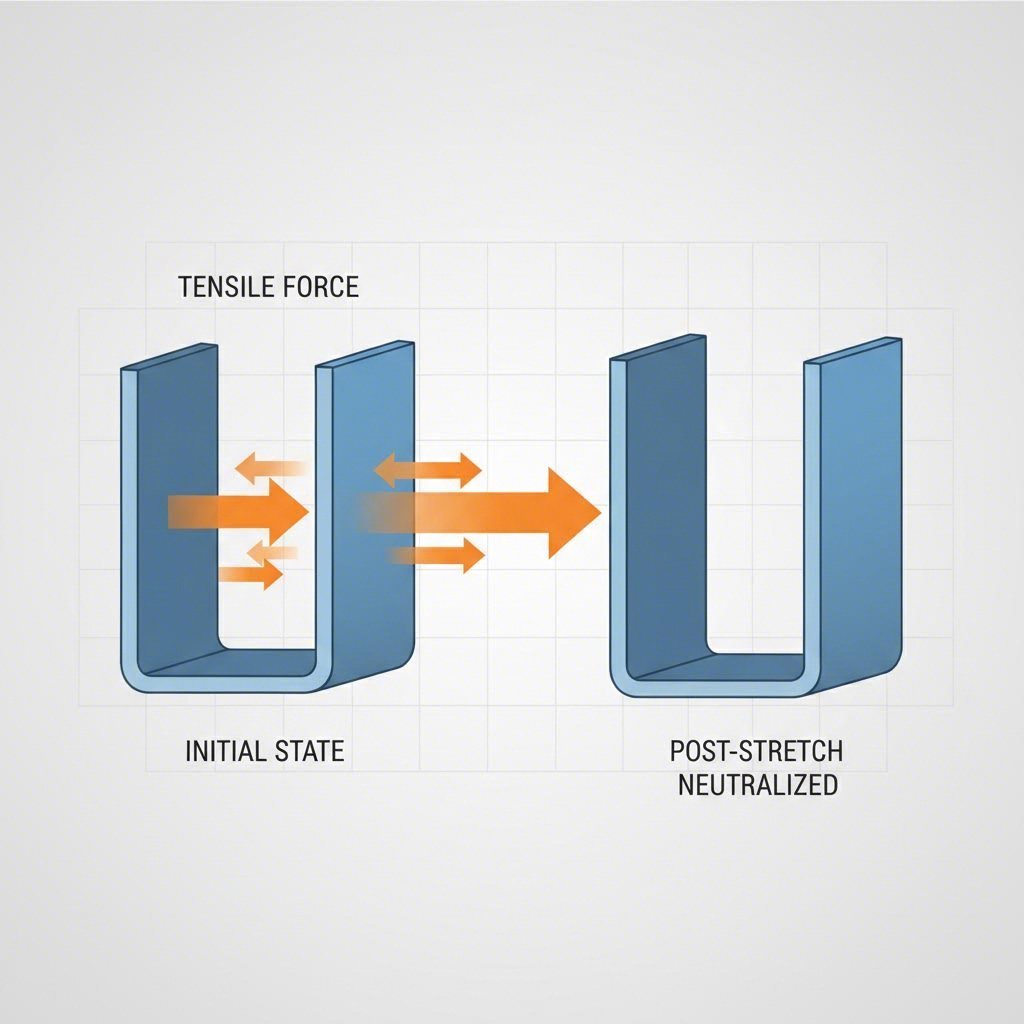
One of the most robust methods for neutralizing sidewall curl—particularly in channel-shaped parts—is changing the elastic strain distribution through post-stretching. The goal is to alter the stress state of the sidewall from a mixed tensile-compressive gradient to a uniform tensile state through the entire thickness.
Implementing Stake Beads
Industry guidelines, including those from WorldAutoSteel, recommend applying an in-plane tensile force to generate a minimum 2% tensile strain in the sidewall. This is often achieved using stake beads (or lock beads) located in the blankholder or on the punch. By engaging these beads late in the press stroke, the process locks the metal and forces the sidewall to stretch. This shift moves the neutral axis out of the sheet metal, effectively equalizing the stress differential ($Δσ$) that drives curling.
While effective, stake beads require significant tonnage and robust die construction. A more material-efficient alternative is the hybrid bead (or stinger bead). Hybrid beads penetrate the sheet metal to create a wave shape that restricts flow, requiring less than 25% of the surface area of conventional stake beads and allowing for smaller blank sizes.
Active Binder Force Control
For presses equipped with advanced cushion systems, active binder force control offers a dynamic solution. Instead of a constant pressure, the binder force can be profiled to increase specifically at the bottom of the stroke. This late-stage pressure spike provides the necessary wall tension to reduce springback without causing early-stage splitting or excessive thinning.
Method 2: Geometric & Tooling Solutions (Overbending & Rotary Bending)
When process parameters alone cannot compensate for high-strength elastic recovery, physical alterations to the tool and part design are necessary. Overbending is the most common technique, where the die is designed to bend the part beyond the target angle (e.g., to 92° for a 90° bend), allowing it to spring back to the correct dimension.
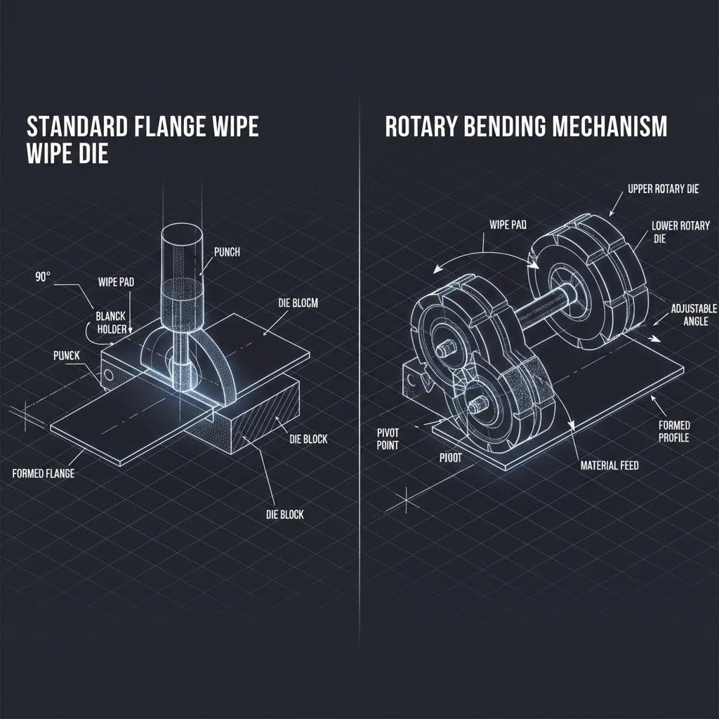
Rotary Bending vs. Flange Wipe Dies
For high-precision AHSS parts, rotary bending is often superior to conventional flange wipe dies. Rotary benders use a rocker to fold the metal, which eliminates the high friction and tensile loading associated with a wipe shoe. This method allows for easier adjustment of the bend angle (often by simply shimming the rocker) to dial in the compensation during tryout.
If flange wipe dies are required, engineers should employ compressive stress superposition. This involves designing the die radius to be slightly smaller than the part radius and using back relief on the punch. This configuration pinches the material at the radius, inducing plastic deformation (compressive yield) that deadens the elastic recovery. Note that this method requires precise control to avoid cracking in higher-grade steels.
Design Stiffeners
Geometry itself can act as a stabilizer. Adding stiffeners, such as step flanges, darts, or beads across the bend line, can "lock in" elastic strains and significantly increase the section modulus. For example, replacing a standard 90-degree hat section with a hexagonal cross-section can inherently reduce sidewall curl by distributing the bending stresses more favorably.
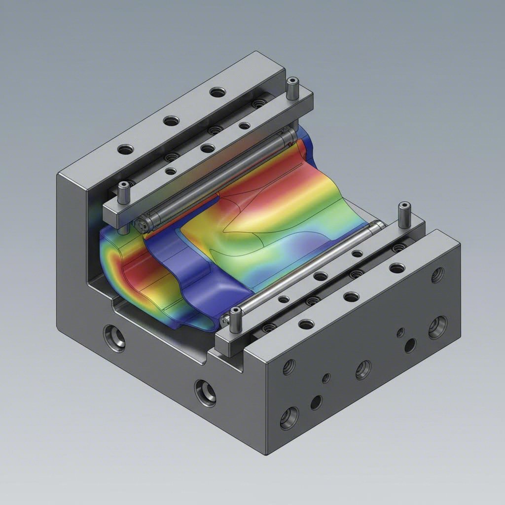
Method 3: Simulation & Full-Cycle FEA
Modern springback management relies heavily on Finite Element Analysis (FEA). However, a common error is simulating only the drawing operation. Accurate prediction requires a Full Cycle Simulation that includes drawing, trimming, piercing, and flanging.
Research from AutoForm highlights that secondary operations significantly influence final springback. For instance, the clamping and cutting forces during trimming can induce new plastic deformations or release residual stresses that alter the part's shape. To achieve simulation reliability, engineers must:
- Use advanced material cards that account for kinematic hardening (Yoshida-Uemori model).
- Simulate the actual tool closure and binder release sequences.
- Incorporate gravity effects (how the part sits on the checking fixture).
By simulating the compensated surface before machining the die, manufacturers can reduce the number of physical recuts loops from 5-7 down to 2-3.
Bridging Simulation and Production
While simulation provides the roadmap, physical validation remains the final hurdle. The transition from a digital model to a physical stamping—especially when scaling from prototype to mass production—requires a manufacturing partner capable of executing these complex compensation strategies. Companies like Shaoyi Metal Technology specialize in bridging this gap. With IATF 16949 certification and press capabilities up to 600 tons, they can validate tooling designs for critical components like control arms and subframes, ensuring that the theoretical compensation aligns with reality on the shop floor.
Comparison of Compensation Strategies
Selecting the right method depends on the part geometry, material grade, and production volume. The table below compares the primary approaches.
| Method | Best Application | Pros | Cons |
|---|---|---|---|
| Overbending | Simple bends, flanging | Low cost, easy to implement in design | Difficult to adjust after machining; limited effect on sidewall curl |
| Post-Stretch (Stake Beads) | Channel parts, rails, sidewall curl | Highly effective for AHSS; stabilizes part geometry | Requires higher press tonnage; increases blank size (scrap rate) |
| Rotary Bending | Flanges with tight tolerances | Adjustable; reduced tool wear; cleaner bends | Higher initial tooling cost; mechanical complexity |
| Compressive Superposition | Tight radii, calibration steps | Very precise dimensional control | Risk of material thinning or cracking; requires high precision |
Conclusion
Solving springback is not about eliminating the laws of physics but mastering them. By combining geometric overbending with process-driven post-stretching and verifying results through rigorous full-cycle simulation, automotive engineers can achieve tight tolerances even with unpredictable AHSS grades. The key is to address stress equalization early in the design phase rather than relying solely on tryout corrections.
FAQ
1. Why is springback more severe in Advanced High-Strength Steel (AHSS) compared to mild steel?
Springback is directly proportional to the yield strength of the material. AHSS grades have significantly higher yield strengths (often 590 MPa to over 1000 MPa) compared to mild steel. This means they can store more elastic energy during deformation, resulting in a greater magnitude of recovery (springback) when the tooling load is released. Additionally, AHSS often exhibits greater work hardening, further complicating the stress distribution.
2. What is the difference between angular change and sidewall curl?
Angular change refers to the deviation of the bend angle (e.g., a 90° bend opening up to 95°) caused by simple elastic recovery at the bend radius. Sidewall curl is a curvature of the flat sidewall itself, caused by a differential in residual stress between the layers of the sheet metal thickness. While angular change can often be fixed with overbending, sidewall curl typically requires tension-based solutions like post-stretching (stake beads) to resolve.
3. Can increasing the binder force eliminate springback?
Simply increasing the binder force globally is rarely enough to eliminate springback in high-strength materials and can lead to splitting or excessive thinning. However, active binder force control—where pressure is increased specifically at the end of the stroke—can effectively apply the necessary sidewall tension (post-stretch) to reduce springback without compromising formability during the initial draw.