 Small batches, high standards. Our rapid prototyping service makes validation faster and easier —

Automotive Metal Stamping Notching: Process & Design Rules
TL;DR
Notching in automotive metal stamping is a precision shearing operation used to remove material from the outer edges of a sheet metal strip or blank. Unlike internal punching, notching creates the external profile of a component and is critical for progressive die functionality, where "pitch notches" control the strip's feed and alignment through the press. This process enables the formation of complex geometries for vehicle chassis, brackets, and structural reinforcements by freeing up material to be bent or drawn without deformation.
For engineers and procurement professionals, mastering notching parameters—such as cutting clearances, width-to-thickness ratios, and corner radii—is essential to prevent common defects like die wear, burrs, and structural cracking, especially when working with modern Advanced High-Strength Steels (AHSS).
The Notching Process in Automotive Stamping
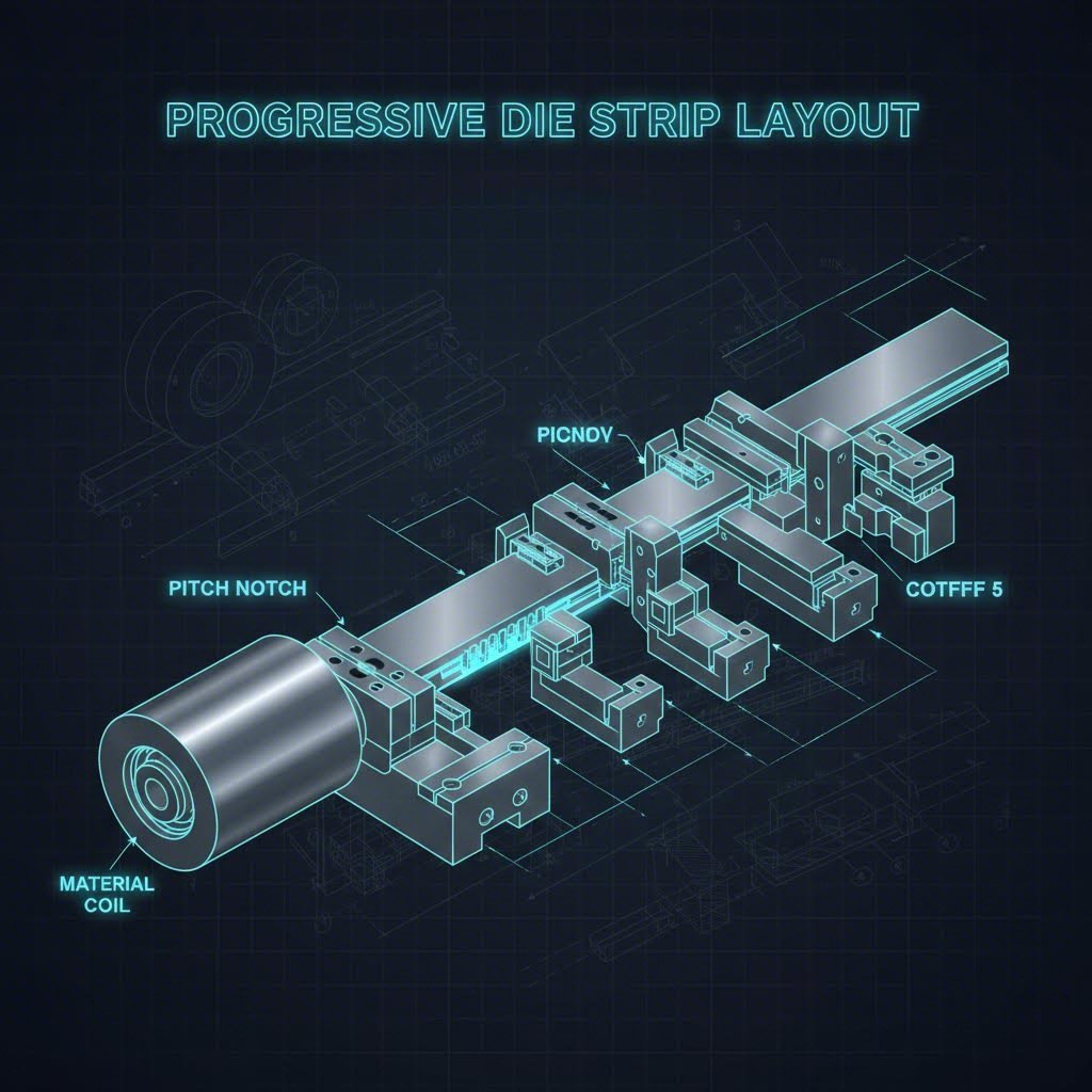
In the high-volume environment of automotive manufacturing, notching is rarely a standalone operation. It is typically integrated into a progressive die sequence, where a continuous coil of steel is fed through a press that performs multiple operations with each stroke. Understanding the mechanics of notching is the first step to optimizing part quality.
Mechanics of the Shear
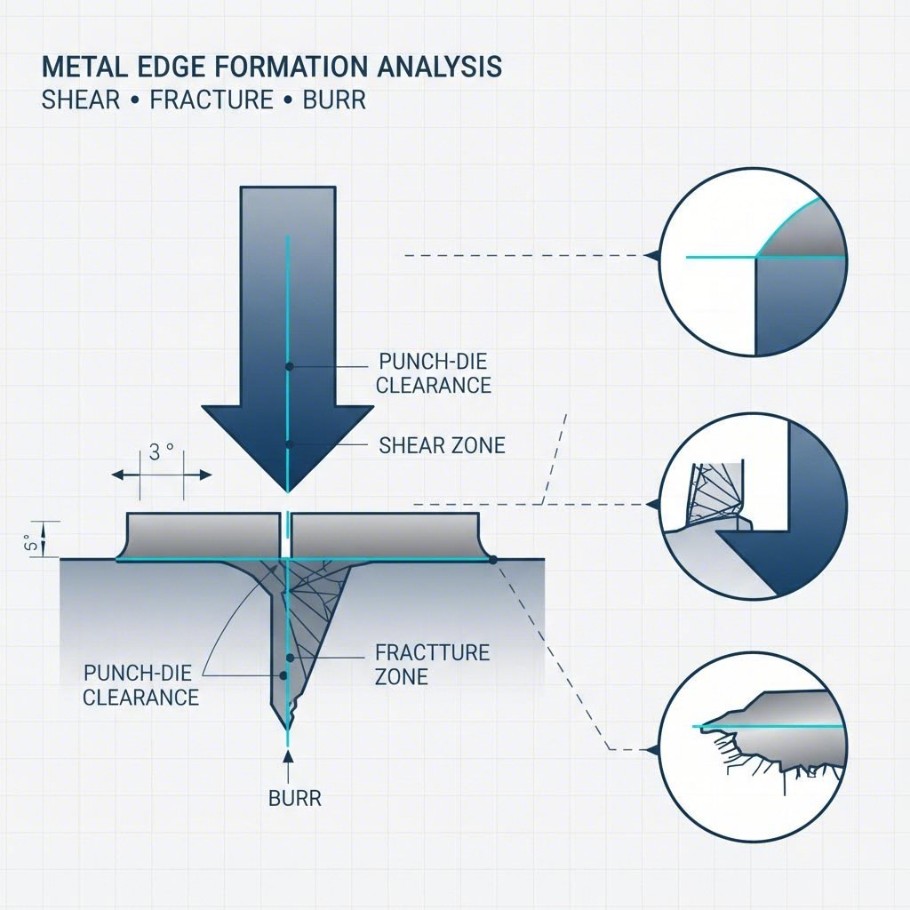
At a fundamental level, notching is a shearing process. A punch (the male tool) forces the sheet metal into a die (the female tool). As the punch contacts the material, it subjects the metal to shear stress until fracture occurs. The quality of this cut edge is defined by the cutting clearance—the gap between the punch and the die. Standard clearance is often around 10% of the material thickness, though this varies based on the material's tensile strength.
- Shear Zone: The shiny, smooth portion of the cut edge where the punch initially penetrates.
- Fracture Zone: The rougher, angled portion where the metal eventually snaps away.
- Burr: The sharp ridge left on the bottom edge; excessive burrs usually indicate incorrect clearance or dull tooling.
The Critical Role of the "Pitch Notch"
In progressive dies, the pitch notch (also called a French notch or side notch) serves a vital logistical function. It cuts a specific shape into the edge of the carrier strip to allow mechanical pilots to locate the strip precisely at each station. Without accurate pitch notching, the strip would misalign as it travels through the die, leading to catastrophic tool crashes or out-of-tolerance parts. This makes the notching station one of the most important aspects of strip layout design.
Critical Design Guidelines for Automotive Notches
Designing robust notches requires adherence to strict engineering constraints. Ignoring these rules often leads to premature tool failure or defective parts. Below are the consensus guidelines for standard automotive sheet metal (steel and aluminum).
The Golden Rules of Notch Geometry
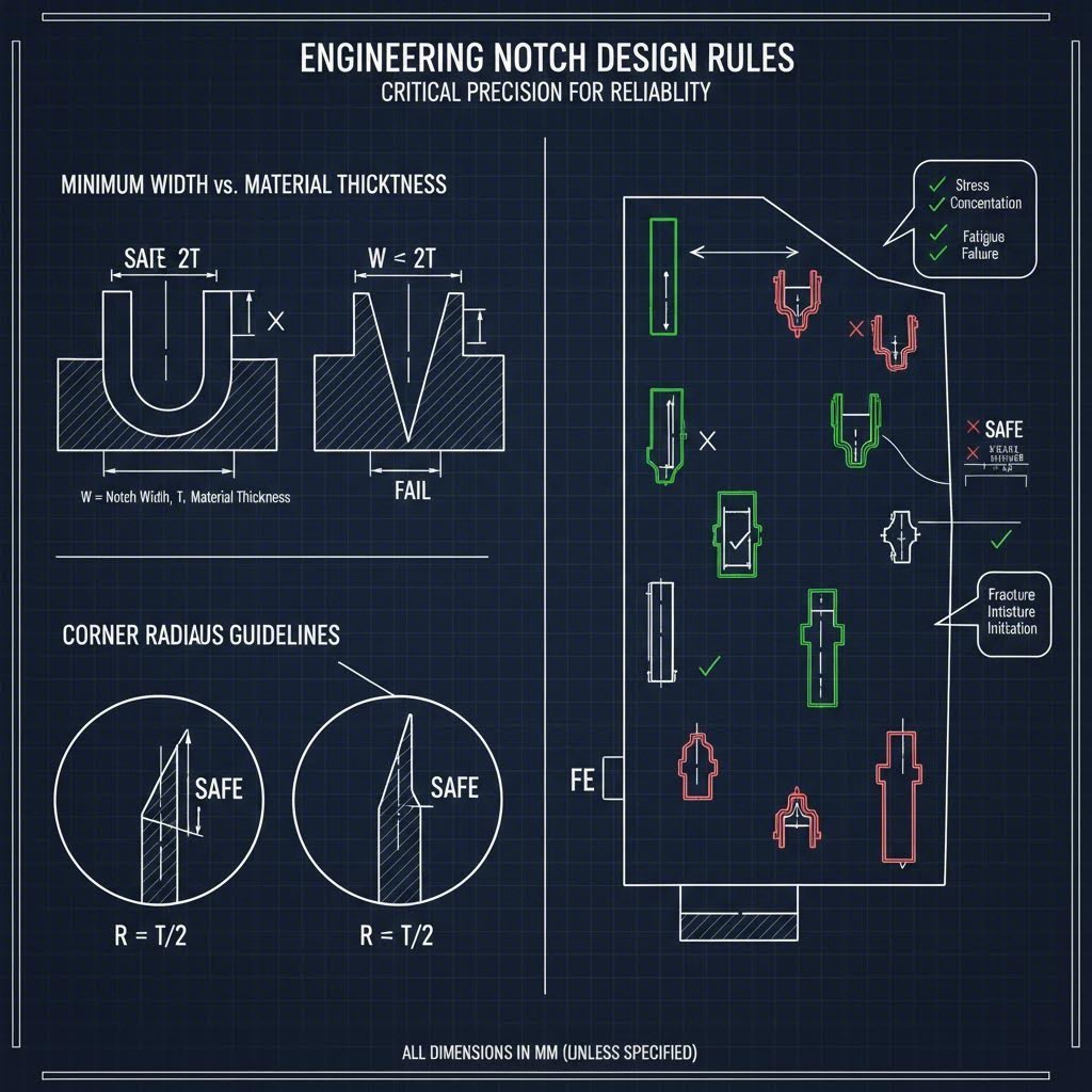
Engineers must balance the desire for tight geometry with the physical limits of the material and tooling. The following parameters are industry standards for ensuring manufacturability:
| Parameter | Design Rule | Engineering Rationale |
|---|---|---|
| Minimum Notch Width | ≥ 1.0x Material Thickness | Prevents punch breakage. Narrower punches are prone to snapping under compressive load. |
| Maximum Notch Depth | ≤ 5.0x Notch Width | Deep, narrow notches increase the risk of punch deflection and wear. |
| Corner Radius | ≥ 0.5x Material Thickness | Sharp corners create stress concentrators that cause cracking, especially in AHSS. |
| Distance to Bend | ≥ 3.0x Material Thickness + Radius | Ensures the notch does not deform during subsequent bending operations. |
Advanced Considerations for AHSS
Automotive bodies increasingly rely on Advanced High-Strength Steels (AHSS) to reduce weight while maintaining safety. Materials like Dual-Phase (DP) or Martensitic steels behave differently than mild steel. When notching AHSS, the shock load on the tooling is significantly higher. Designers should increase the minimum notch width to 1.5x material thickness and use generous corner radii to prevent the part from splitting during crash events or fatigue cycles.
Automotive-Specific Challenges & Solutions
The automotive sector demands zero-defect manufacturing at high speeds. This environment introduces unique challenges that standard fabrication shops often fail to address.
Slug Pulling and Scrap Management
When a notch is cut, the removed piece of metal (the slug) must be ejected from the die. In high-speed stamping, the vacuum created by the retracting punch can pull the slug back up onto the die face—a phenomenon known as slug pulling. If a slug lands on the strip, the next press stroke drives it into the part, creating "pimple" defects or smashing the die.
Solutions:
- Ejector Pins: Spring-loaded pins inside the punch to physically push the slug down.
- Vacuum Dies: Suction systems beneath the die block to pull slugs away.
- Shear Angles: Grinding a slight angle on the punch face to reduce the vacuum seal.
Tool Wear in High-Volume Production
A typical automotive stamping run might require hundreds of thousands of hits per month. Standard tool steels (like D2) often degrade too quickly when notching abrasive automotive grades. Leading manufacturers now utilize Powdered Metallurgy (PM) steels or Carbide punches coated with TiCN (Titanium Carbonitride) to extend service life and maintain edge quality.
Bridging Prototyping and Mass Production
One of the most difficult phases in automotive development is the transition from low-volume prototypes to mass production. Prototyping often uses laser cutting (which creates no burrs or stress), while production uses hard tooling (which introduces shear stress). This discrepancy can lead to unforeseen failures during validation.
To mitigate this risk, it is crucial to partner with manufacturers who can simulate production conditions early. Shaoyi Metal Technology specializes in bridging this gap, offering comprehensive stamping solutions that range from rapid prototyping to high-volume manufacturing. With IATF 16949-certified precision and press capabilities up to 600 tons, they handle critical components like control arms and subframes, ensuring that the engineering intent survives the transition to mass production.
Machinery & Tooling: Progressive vs. Transfer Dies
The choice of die technology fundamentally changes how notching is executed. The correct selection depends on part complexity and annual volume.
Progressive Dies
In a progressive die, the notching operation is performed while the part is still attached to the coil strip. The notches define the part's shape step-by-step. This is the most efficient method for small-to-medium automotive parts (brackets, clips, connectors) because it yields a finished part with every stroke. However, the strip layout is complex, and material utilization can be lower due to the need for a carrier web.
Transfer Dies
For larger parts like body panels, pillars, or cross-members, transfer dies are preferred. Here, a blank is cut (notched) in the first station and then mechanically transferred by robotic fingers to subsequent stations. Notching in transfer dies is often used for developed blanks—creating the complex flat shape required to form a deep-drawn part without wrinkling. Transfer dies allow for better material utilization but operate at slower speeds than progressive dies.
Engineering for Precision and Performance
Notching is more than just cutting metal; it is a strategic operation that dictates the efficiency of the stamping line and the structural integrity of the final vehicle component. Whether optimizing for the pitch notch in a progressive die or calculating corner radii for AHSS brackets, success lies in the details. By adhering to proven design ratios and selecting the right tooling partners capable of handling high-tonnage demands, automotive engineers can ensure their designs are not just manufacturable, but robust enough for the road ahead.
Frequently Asked Questions
1. What is the difference between trimming and notching?
While both are cutting operations, the distinction lies in their purpose and geometry. Notching removes a specific shape from the outer edge of the workpiece, often to facilitate bending or assembly. Trimming is typically a finishing operation used to cut away excess material (flash) from the perimeter of a drawn or formed part to bring it to its final dimensions.
2. What defines the "notching" process in metalworking?
Notching is a shearing process used to remove a portion of material from the edge of a metal sheet or strip. It is performed using a punch press where a cutting tool forces the metal against a die edge, shearing it to create a profile, relief, or clearance for subsequent forming steps.
3. Why is the width-to-thickness ratio important in notching?
The width-to-thickness ratio is critical for tool life. A notch width that is narrower than the material thickness (a ratio less than 1:1) imposes excessive compressive stress on the punch, causing it to deflect or snap. Adhering to the 1:1 minimum rule ensures the tooling acts as a cutting implement rather than a column under load.