 Small batches, high standards. Our rapid prototyping service makes validation faster and easier —

Sheet Metal Production Secrets: 9 Essential Points Engineers Miss
What Is Sheet Metal Production and Why It Matters
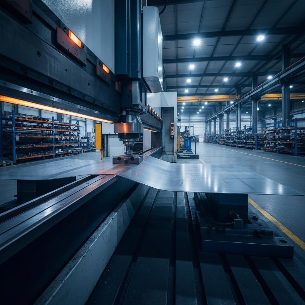
Ever wondered how a flat, unassuming metal sheet transforms into the intricate components inside your car or the sleek enclosure protecting your electronics? That's the magic of sheet metal production - a manufacturing discipline that turns raw material into precision-engineered parts through cutting, bending, and forming operations.
So, what is sheet metal exactly? It's a thin, flat form of metal created by passing hot metal through industrial rolling equipment. According to Zetwerk's technical resources, this material can range from a few thousandths of an inch to several millimeters thick, making it remarkably versatile for countless applications.
From Raw Material to Precision Component
Sheet metal manufacturing is the process of creating functional parts by cutting, bending, and forming thin metal sheets into specific shapes and sizes. You'll find these components everywhere - from the body panels on vehicles to airplane wings, kitchen appliances, and architectural elements.
Here's a quick distinction that trips up many engineers: what are sheet metals versus plate metals? The industry typically classifies material between 0.5mm and 6mm thickness as sheet metal, while anything thicker falls into plate territory. This distinction matters because thickness directly impacts which forming processes you can use and what equipment you'll need.
The Foundation of Modern Manufacturing
Understanding all about sheet metal production means recognizing its three core process categories:
- Cutting operations - Shearing, punching, laser cutting, and blanking to achieve desired sizes
- Forming processes - Bending, stamping, rolling, and spinning to create three-dimensional shapes
- Assembly techniques - Welding, riveting, and fastening to join components together
Throughout this guide, you'll discover the essential points that separate successful sheet metal projects from costly failures. We'll cover material selection criteria, detailed process specifications, quality control standards, and design-for-manufacturability guidelines that most resources overlook. Whether you're specifying parts for automotive applications or designing electronic enclosures, these insights will help you make smarter manufacturing decisions.
Essential Materials Used in Sheet Metal Manufacturing
Choosing the wrong sheet metal material can derail your entire project - driving up costs, delaying production, or causing premature failure in service. Yet many engineers rush through material selection, focusing solely on price or availability. The truth? Understanding different types of sheet metal material is just as critical as nailing your design specifications.
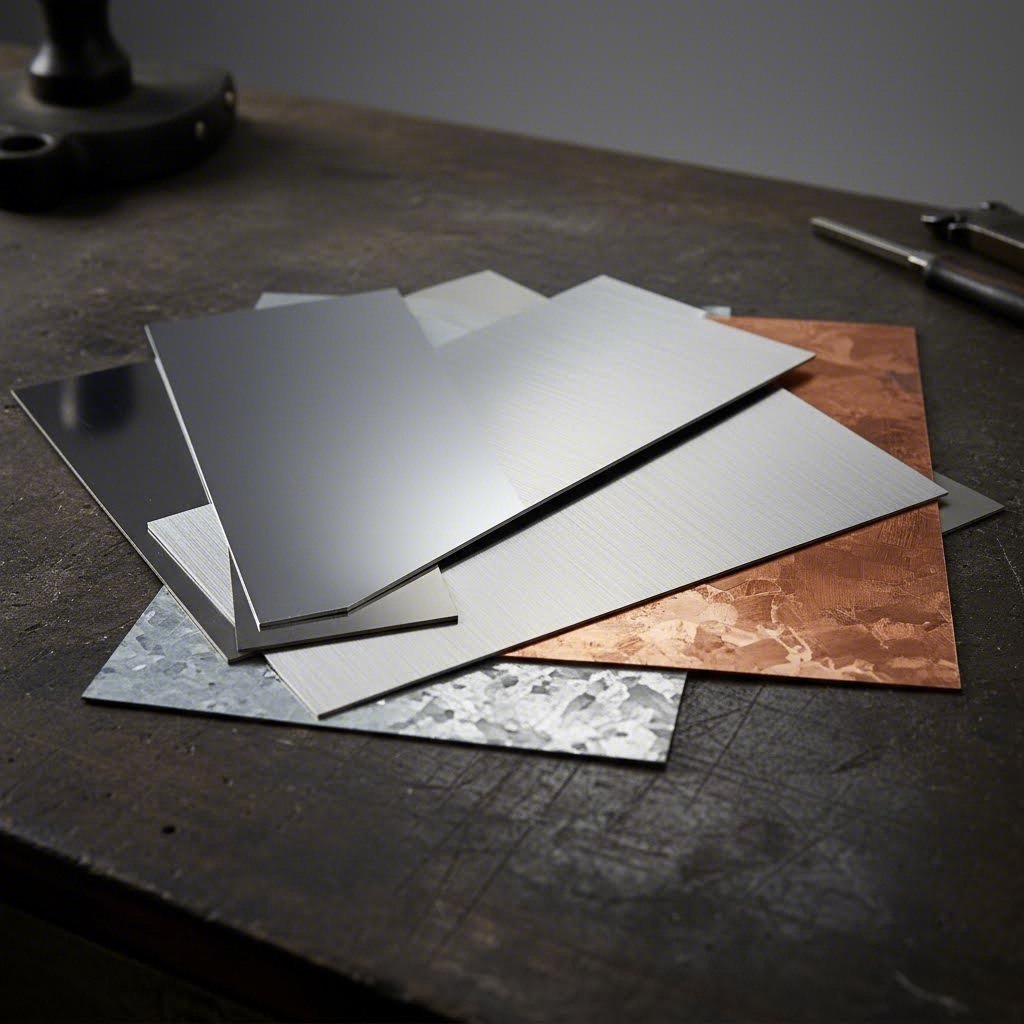
Let's break down the types of metal sheets you'll encounter most frequently and when each one makes sense for your application.
Aluminum for Lightweight Applications
When weight reduction matters, aluminum sheet metal fabrication becomes your go-to solution. With a density of just 2.7 g/cm³ - roughly one-third that of steel - aluminum alloys like 6061 deliver an excellent strength-to-weight ratio that's hard to beat.
What makes aluminum particularly attractive for sheet metals applications?
- Natural corrosion resistance - Forms a protective oxide layer without additional coatings
- Excellent formability - Tolerates bends at approximately 1× material thickness
- Superior machinability - Reduces tool wear and machining time during fabrication
- Recyclability - Highly sustainable with excellent environmental credentials
You'll find aluminum dominating consumer electronics enclosures, aerospace components, automotive lightweighting projects, and heat sink applications. The trade-off? Aluminum's lower fatigue strength means it may not hold up as well under repeated stress cycles compared to steel alternatives.
Steel and Stainless Steel Properties
Steel sheet metal material remains the workhorse of industrial manufacturing - and for good reason. With tensile strengths ranging from 250 to 1,500 MPa depending on the grade, steel delivers unmatched structural performance at competitive pricing.
Here's where it gets interesting: the choice between carbon steel and stainless steel often makes or breaks project success.
Cold-rolled carbon steel offers high strength, smooth surfaces, and precision at the lowest cost. It's ideal for automotive parts, appliance housings, and furniture frames - anywhere corrosion isn't your primary concern. The catch? You'll need surface protection like painting or plating to prevent rust.
Stainless steel (304/316 grades) changes the game entirely. According to Okdor's material selection guide, stainless steel's chromium content forms a self-healing oxide layer that delivers exceptional corrosion resistance - even in humid, chemical, or marine environments. Grade 316 performs especially well in aggressive conditions.
The drawback? Stainless steel is more difficult to process due to higher strength and lower thermal conductivity. Expect greater forming force requirements and stricter process control.
Specialty Metals and Alloys
Beyond the aluminum and steel families, several specialty sheet metal materials serve specific performance needs:
- Copper - Offers excellent electrical and thermal conductivity (the highest among common sheet metals), good formability, and antimicrobial properties. Ideal for electrical components, heat exchangers, and decorative elements. However, its density of 8.96 g/cm³ and higher cost limit it to applications where conductivity is the core function.
- Galvanized steel - Cold-rolled steel with a zinc coating for corrosion protection. A cost-effective middle ground for HVAC systems, fencing, roofing, and ductwork where moderate outdoor durability is needed.
- Brass - Combines good formability with aesthetic appeal, polishing well for decorative applications. Prone to tarnish without protective finishing.
The table below provides a quick-reference comparison of sheet metal materials to guide your selection:
| Material | Formability | Corrosion Resistance | Strength-to-Weight | Relative Cost | Best Applications |
|---|---|---|---|---|---|
| Aluminum (6061) | Excellent | Good (anodize for better) | Excellent | 1.3-1.5× | Aerospace, electronics, enclosures |
| Cold-Rolled Steel | Excellent | Poor (needs coating) | Moderate | 1.0× (baseline) | Automotive, appliances, structures |
| Stainless Steel (304) | Moderate | Excellent | Moderate | 2-3× | Medical, food processing, marine |
| Galvanized Steel | Good | Good | Moderate | 1.2-1.4× | HVAC, roofing, outdoor structures |
| Copper | Good | Excellent | Low | 4-6× | Electrical, heat exchangers |
One common mistake we see? Over-specifying materials. Choosing 316 stainless when 304 would work, or 7075 aluminum when 6061 is sufficient, raises both cost and sourcing time without meaningful benefit. Start with performance requirements - strength, stiffness, corrosion resistance, weight, and conductivity - then map materials against those actual needs.
With your material selection locked in, the next critical decision involves understanding which forming processes will shape your components most effectively.
Metal Forming Processes That Shape Your Components
Imagine trying to fold a piece of cardboard versus a rigid plastic sheet. One bends easily; the other cracks. The same principle applies to forming sheet metal - your choice of forming process must match both the material properties and the geometry you're trying to achieve.
The metal forming process you select determines everything from production speed to part quality and cost per unit. According to research from the Indian Institute of Technology Guwahati, sheet metal forming involves plastic deformation where stresses exceed the material's yield strength, permanently reshaping the workpiece without removing material. Let's explore the core techniques that transform flat sheets into functional components.
Bending and Press Brake Operations
Bending is the workhorse of sheet metal forming - a process where metal is strained around a straight axis to create angular shapes. During this operation, the material on the inner side compresses while the outer surface stretches, with a neutral plane running through the middle experiencing minimal strain.
Press brake operations use a punch and die setup to create precise bends. The two primary methods are:
- V-bending - The sheet is pressed between a V-shaped punch and die, producing angles from very obtuse to acute. This method offers excellent control over bend angle and is ideal for simple brackets, enclosures, and structural components.
- Edge bending - Uses cantilever loading where a pressure pad holds the sheet against the die while the punch forces it to yield over the die edge. Best suited for flanges and hem features.
Here's something many engineers overlook: springback. When you release the forming load, the elastic zone near the neutral axis tries to return to its original flat condition. The plastically deformed regions resist, but some recovery still occurs. This means you'll often need to overbend or use bottoming techniques to hit your target angle consistently.
Key characteristics of bending operations:
- Minimal material thinning when bend radius exceeds material thickness
- Bend radius limitations depend on material ductility and grain direction
- Inside bend radius typically ranges from 1× thickness for ductile alloys to 3-4× for harder tempers
- Springback increases with higher yield strength materials
Stamping and Deep Drawing Explained
When you need complex three-dimensional shapes at high volumes, stamping and deep drawing become your go-to forming processes. These operations use matched punch and die sets to transform flat blanks into intricate geometries.
Stamping combines multiple operations - blanking, piercing, bending, and forming - often in progressive dies that perform several steps with each press stroke. It's the backbone of automotive body panel production and appliance manufacturing.
Deep drawing takes forming sheet metal to another level. In this process, a flat sheet (called a blank) is pushed by a punch into a die cavity, creating cup-shaped or box-shaped parts. A blank holder clamps the material to control flow and prevent wrinkling.
Here's what happens during steel sheet forming in deep drawing:
- Initial contact - The punch contacts the blank and begins pushing it into the die opening
- Bending phase - Material bends over the punch corner and die corner radii
- Drawing phase - The blank's outer edge flows inward toward the die cavity as the cup wall forms
- Ironing (optional) - If clearance between punch and die is less than material thickness, the wall thins for tighter tolerance
The drawing ratio - blank diameter divided by punch diameter - indicates how severe the operation is. A ratio exceeding 2.0 typically requires multiple drawing stages (redrawing) to avoid tearing. First draws can achieve 40-45% reduction, with subsequent passes limited to progressively smaller reductions.
Material properties critically affect deep drawing success. The plastic strain ratio (R-value) measures a sheet's resistance to thinning - higher values mean better drawability. Anisotropy also matters; variations in properties at different orientations can cause "earing" defects where cup walls develop uneven heights.
Roll Forming for Continuous Profiles
Need consistent cross-sectional profiles in long lengths? Sheet metal roll forming delivers exactly that. This continuous forming process passes strip material through a series of roll stations, each incrementally bending the sheet until the final shape emerges.
Unlike stamping or press brake operations, roll forming excels at producing:
- Structural sections (C-channels, Z-purlins, hat sections)
- Architectural trim and siding profiles
- Automotive structural rails
- Racking and shelving components
The process offers several distinct advantages:
- High production rates - Material feeds continuously at speeds up to 100+ feet per minute
- Excellent length flexibility - Cut parts to any length without die changes
- Consistent quality - Once set up, profile dimensions remain stable across production runs
- Material efficiency - Minimal scrap compared to stamping operations
The trade-off? Tooling costs for roll forming lines are substantial, and the process only makes economic sense at higher volumes where that investment spreads across thousands of feet of material.
Stretch Forming and Specialized Techniques
For large, gently curved panels - think aircraft fuselage skins or architectural facades - stretch forming combines tension with bending to minimize springback. The sheet is gripped at both ends, stretched beyond yield, then wrapped over a form die. Because the entire cross-section undergoes plastic deformation, elastic recovery is dramatically reduced.
The forming process you ultimately select depends on several interconnected factors:
| Process | Best For | Volume Sweet Spot | Typical Tolerances |
|---|---|---|---|
| Press Brake Bending | Brackets, enclosures, simple angles | Low to medium | ±0.5mm angles |
| Stamping | Complex flat/shallow parts, high volume | High (10,000+) | ±0.1-0.25mm |
| Deep Drawing | Cup/box shapes, cylindrical parts | Medium to high | ±0.1-0.5mm |
| Roll Forming | Continuous profiles, structural sections | High volume/length | ±0.25-0.5mm |
| Stretch Forming | Large curved panels, aerospace skins | Low to medium | ±1-2mm |
Understanding these forming metal sheet fundamentals positions you to specify the right process from the start. But forming is only part of the equation - cutting and machining operations determine how your blanks are prepared and finished, which we'll explore next.
Cutting and Machining Operations in Sheet Metal Work
You've selected your material and identified the forming process - but how does that flat sheet become a workable blank in the first place? That's where sheet metal cutting and machining operations enter the picture. Choosing the wrong cutting method can mean blown tolerances, rejected parts, and costly rework that derails your production schedule.
Here's what most engineers miss: each cutting technology has a precision sweet spot, and matching it to your application makes all the difference in quality, cost, and lead time.
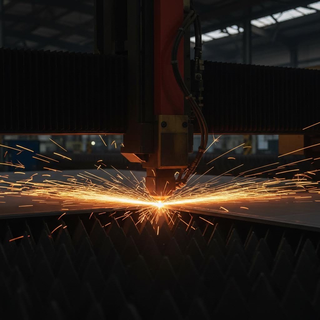
Laser Cutting Precision and Speed
Laser cutting dominates sheet metal machining for thin to medium materials requiring intricate geometries and clean edges. The focused beam of light melts, burns, or vaporizes material with surgical precision - achieving tolerances of ±0.05-0.1mm on most materials up to 25mm thick.
What makes laser cutting the go-to choice for precision metal processing?
- Exceptional edge quality - Minimal burrs and smooth finishes often eliminate secondary operations
- Intricate geometry capability - Small holes, tight corners, and complex contours are easily achievable
- High processing speed - Fiber lasers cut thin aluminum and steel significantly faster than alternative methods
- Narrow kerf width - Less material waste compared to plasma or mechanical cutting
The trade-off? Laser cutting effectiveness drops significantly on thick sections. According to Wurth Machinery's cutting technology comparison, attempting 35mm stainless steel results in ±0.3mm tolerance drift and degraded edge quality due to heat accumulation. For materials under 15mm, though, laser cutting delivers the optimal balance of speed and precision.
Plasma cutting fills the gap when you're working with thicker conductive metals. Using an electrical arc and compressed gas to melt and blast through material, plasma handles 1-inch steel plate roughly 3-4 times faster than waterjet - with operating costs about half as much per foot. Tolerances range from ±0.5-1.5mm, making plasma ideal for structural fabrication where tight specs aren't critical.
Waterjet cutting emerges as the precision leader when thermal effects must be avoided entirely. By mixing high-pressure water (up to 90,000 PSI) with abrasive garnet, waterjet cuts virtually any material - steel, aluminum, titanium, stone, glass, composites - without heat-affected zones. Tolerances of ±0.03-0.08mm remain consistent regardless of thickness, making it indispensable for aerospace components, medical devices, and heat-sensitive materials.
Punching and Shearing Operations
While thermal cutting methods excel at complex contours, mechanical sheet metal cutting through punching and shearing remains essential for high-volume production and specific geometries.
Shearing separates sheet material using opposing blades - one stationary, one driven downward. According to CustomPartNet's technical library, the process handles sheet thickness from 0.005 to 0.25 inches with tolerances of ±0.1 inches (±0.005 inches feasible). It's primarily used for cutting stock into smaller blanks before subsequent operations.
Here's what happens at the shear edge:
- Rollover zone - Initial plastic deformation as the blade contacts the sheet
- Burnished zone - Vertical, smooth region created by shearing action
- Fracture zone - Angled break where material fails, with slight burr formation
Punching removes material using a punch and die set, creating holes, slots, and cutouts. CNC punch presses deliver around 600 strokes per minute, with turrets holding up to 100 different punch shapes. The key punching variations include:
- Piercing - Standard cylindrical hole creation
- Blanking - Removing the desired part shape (the blank is kept, not scrapped)
- Nibbling - Overlapping punches along a path to create larger contours without custom tooling
- Notching - Removing material from sheet edges
- Lancing - Partial cuts creating tabs, vents, or louvers without material removal
For sheet metal pressings and blanked parts requiring superior flatness and edge quality, fine blanking applies three simultaneous forces - holding, cushioning, and punching - to achieve tolerances as tight as ±0.0003 inches. This eliminates secondary finishing on high-precision components like gears and watch parts.
CNC Integration in Modern Production
Here's where cnc sheet metal forming and cutting truly shine. Computer numerical control transforms cutting operations from manual setups into repeatable, lights-out manufacturing.
CNC integration enhances every cutting method:
- Program-driven accuracy - Eliminates operator variability between parts and batches
- Rapid changeover - Switch between jobs in minutes rather than hours of manual setup
- Nesting optimization - Software arranges parts to minimize material waste
- Process documentation - Every cut is recorded for quality traceability
Modern CNC punch presses, laser cutters, and waterjet systems can be hydraulically, pneumatically, or electrically powered. The result? Consistent tolerances across thousands of parts with minimal human intervention.
The following table compares cutting methods across the specifications that matter most for your metal operation decisions:
| Cutting Method | Precision (Tolerance) | Speed | Material Compatibility | Thickness Range | Edge Quality |
|---|---|---|---|---|---|
| Laser Cutting | ±0.05-0.1mm | Very High | Most metals, some non-metals | Up to 25mm | Excellent, minimal burrs |
| Plasma Cutting | ±0.5-1.5mm | High | Conductive metals only | Up to 150mm+ | Good, some dross |
| Waterjet Cutting | ±0.03-0.08mm | Moderate | Any material | Up to 200mm | Excellent, no HAZ |
| Punching | ±0.1-0.3mm | Very High (600+ SPM) | Sheet metals | Up to 6mm typical | Good, burrs on exit side |
| Shearing | ±0.1-0.5mm | High | Sheet metals | Up to 6mm typical | Moderate, fracture zone visible |
Reserve tight tolerances (±0.05mm or better) for functional features like assembly fits and seal surfaces. Standard tolerances reduce cutting time, inspection complexity, and fabrication costs without compromising part performance.
With blanks cut to specification, the next challenge becomes joining those components into functional assemblies - where welding, fastening, and bonding techniques determine structural integrity.
Sheet Metal Assembly and Joining Techniques
You've cut and formed your components to specification - now comes the moment of truth. Will those parts actually fit together? Sheet metal assembly is where individual components become functional products, and it's also where tolerance problems, material incompatibilities, and design oversights come back to haunt you.
Here's what separates successful sheet metal work from costly rework: understanding that joining isn't just about connecting parts - it's about managing the cumulative effect of every manufacturing variation that came before. Let's explore the techniques that make or break your assemblies.
Welding Techniques for Sheet Metal
When you need permanent, high-strength joints, welding remains the gold standard for sheet metal working. According to 3ERP's welding methods guide, welded joints offer structural integrity that fasteners simply can't match - plus they're watertight and aesthetically clean when done right.
But not all welding processes suit every sheet metal application. Here's how the primary methods compare:
MIG Welding (Gas Metal Arc Welding)
MIG welding feeds a continuous wire that acts as both electrode and filler material. The arc forms between this wire and your workpiece, melting both to create the joint. It's fast, affordable, and forgiving for operators - making it ideal when efficiency trumps precision.
- Best for mild steel and thicker gauge materials
- High deposition rates enable rapid production
- Lower skill requirements compared to TIG
- Trade-off: Less precise control means potential for spatter and less aesthetic welds
TIG Welding (Gas Tungsten Arc Welding)
TIG welding uses a non-consumable tungsten electrode while the operator feeds filler rod separately with the other hand. This two-handed technique demands skill but delivers superior results.
- Produces the cleanest, most cosmetic finishes
- Ideal for thin sheet metal where precision prevents burn-through
- Excellent for stainless steel, aluminum, and visible seams
- Trade-off: Slower speeds and higher operator skill requirements
Spot Welding (Resistance Welding)
Spot welding creates localized "spots" between overlapping sheets using copper electrodes that concentrate current and apply pressure simultaneously. It's the backbone of automotive body assembly - a single car can have thousands of individual spot welds.
- Extremely fast and easily automated
- Minimal heat distortion to surrounding material
- Best for thin-gauge materials up to 3mm thick
- Trade-off: Lower individual weld strength; joints aren't watertight
Mechanical Fastening Options
Sometimes you don't want permanence. Working with sheet metal often means designing for serviceability - the ability to disassemble, repair, and replace components throughout a product's life. That's where mechanical fastening shines.
According to Fictiv's metal assemblies guide, mechanical fasteners offer distinct advantages over welding:
- Disassembly capability - Critical for maintenance, upgrades, and end-of-life recycling
- No heat-affected zones - Preserves material properties near the joint
- Joins dissimilar materials - Connect aluminum to steel without galvanic welding issues
- Lower skill requirements - Standard sheet metal workers tools can complete most fastening operations
Self-clinching fasteners (PEMs) permanently install into sheet metal during fabrication, providing threaded holes or studs without welding. They're essential for thin materials that can't support tapped threads.
Rivets create permanent mechanical joints by deforming a shaft to lock components together. Pop rivets (blind rivets) allow one-sided access, while solid rivets deliver maximum shear strength for structural applications.
Adhesive bonding deserves mention alongside mechanical fastening. Structural adhesives distribute stress across the entire bond area rather than concentrating it at fastener holes. They excel where weight matters - aerospace and electronics assemblies often combine adhesives with spot welds or fasteners for redundant, lightweight joints.
Design Considerations for Assembly
Here's what trips up even experienced engineers: tolerance stackup. Every part you fabricate sheet metal from carries its own dimensional variation. When multiple components come together, those small deviations accumulate - sometimes preventing assembly entirely.
According to Hotean's tolerance analysis, consider a simple three-bracket assembly where each bracket has ±0.5mm hole position tolerance. In the worst case, all tolerances align in the same direction, creating 1.5mm total misalignment - enough to make screw installation impossible.
Smart sheet metal fabrication and assembly design addresses this proactively:
- Use datum features strategically - Establish primary locating points with round holes at tight tolerance, then use slots elsewhere to absorb variation
- Follow the 3-2-1 principle - Constrain all six degrees of freedom systematically using three primary datum points, two secondary points, and one tertiary point
- Orient slots correctly - Slots absorb variation only in their long direction; orient them to accommodate your calculated stackup direction
- Specify assembly sequence - Note on drawings which fasteners to tighten first to ensure datum features engage before adjustment slots are locked
When selecting your joining method, weigh these criteria against your specific requirements:
- Strength requirements - Welding for maximum load capacity; fasteners for moderate loads with serviceability
- Production volume - Spot welding and automated fastening for high volume; manual TIG/MIG for prototypes and low quantities
- Material compatibility - Fasteners or adhesives when joining dissimilar metals; welding for same-material joints
- Aesthetic requirements - TIG welding or concealed fasteners for visible surfaces
- Service life expectations - Fasteners enable field repair; welding provides permanent, maintenance-free joints
The joining method you select ripples through your entire design. It affects hole placement, edge distances, material selection, and ultimately your quality control requirements - which brings us to the standards and tolerances that ensure consistent results.
Quality Control and Tolerance Standards
Your parts look good coming off the line - but will they actually fit in assembly? Will they survive field conditions? Quality control separates sheet metal components that perform from those that fail in service. Yet most resources gloss over the specifics, leaving engineers to figure out tolerance requirements and defect prevention on their own.
Here's the reality: understanding how to specify tolerances correctly - and catching defects before they ship - saves more money than any other aspect of the sheet metal process. Let's break down the standards, common failure modes, and certification requirements that ensure consistent quality.
Tolerance Standards and Specifications
When you don't specify individual tolerances on every feature, international standards fill the gap. According to Xometry's tolerance standards guide, ISO 2768 and ISO 286 provide the framework most sheet metal operations follow - reducing documentation overhead while maintaining acceptable precision.
ISO 2768 applies to general tolerances for features without explicit callouts:
- Linear dimensions (lengths, widths, heights)
- External radii and chamfer heights
- Angular dimensions
For precision sheet metal forming requiring tighter control, ISO 286 defines tolerance grades for specific features like hole diameters and fits. The most common grades you'll encounter:
- IT6 - Tight tolerance for precision fits (±19µm for 50-80mm nominal)
- IT7 - Standard precision applications (±30µm for 50-80mm nominal)
- IT8 - General purpose machining (±46µm for 50-80mm nominal)
Reserve tight tolerances for functional features only. Over-specifying raises costs without improving part performance.
For sheet metal processing operations, typical achievable tolerances vary by process:
| Operation | Standard Tolerance | Fine Tolerance (Achievable) |
|---|---|---|
| Laser Cutting | ±0.1mm | ±0.05mm |
| Press Brake Bending | ±0.5° angle | ±0.25° |
| Punching | ±0.1-0.3mm | ±0.05mm |
| Deep Drawing | ±0.25mm | ±0.1mm |
Common Defects and Prevention
Every metal operation introduces potential failure modes. According to The Phoenix Group's defect analysis, understanding root causes is essential for prevention.
The most frequent defects in sheet metal components include:
- Springback - Material partially returns to flat after bending. Caused by elastic recovery along the neutral axis. Prevention: Overbend, use smaller radii, or add coining/set beads.
- Splitting - Tears when strain exceeds ultimate tensile strength. Usually occurs in high-stretch areas. Prevention: Reduce strain, increase stretch in the minor direction, or use multi-stage forming.
- Wrinkling - Compression zones buckle and fold. Common in draw corners. Prevention: Reduce compression, add material-consuming features, or use higher R-value materials.
- Burrs - Sharp edges from cutting operations. Caused by dull tools, improper clearance, or misalignment. Prevention: Sharpen tooling, verify mounting, and set proper punch-die clearance.
- Necking/Thinning - Localized wall reduction in formed areas. Prevention: Larger radii, shallower draft angles, improved lubrication, or higher R-value material.
- Cracking - Fractures in compression zones, especially draw corners. Prevention: Stress-relieve material, reduce compression forces.
Material-related issues like coil camber, edge wave, and bowing often originate at the mill and may require ordering slit coils or adjusting feed equipment alignment.
Quality Certifications That Matter
When your sheet metal components feed into demanding industries, quality certifications provide objective validation of manufacturing capability.
IATF 16949 is the gold standard for automotive supply chains. It builds on ISO 9001 fundamentals but adds automotive-specific requirements for:
- Advanced product quality planning (APQP)
- Production part approval process (PPAP)
- Failure mode and effects analysis (FMEA)
- Statistical process control (SPC)
Other relevant certifications include:
- ISO 9001 - General quality management systems foundation
- AS9100 - Aerospace-specific quality requirements
- ISO 13485 - Medical device manufacturing
Surface finish inspection typically follows Ra (roughness average) measurements, with common specifications ranging from Ra 3.2µm for standard finishes to Ra 0.8µm for precision surfaces. Coordinate measuring machines (CMMs) verify critical dimensions, while visual inspection standards define acceptable cosmetic quality levels.
With quality standards established, the next step is ensuring your designs can actually be manufactured consistently - which is where design-for-manufacturability guidelines prevent problems before they reach the shop floor.
Design Guidelines for Efficient Sheet Metal Production
You've specified the right material, selected your forming process, and established quality standards - but here's where many projects still fall apart. Poor sheetmetal design choices made early in development cascade into manufacturing headaches, rejected parts, and blown budgets. The frustrating part? Most of these issues are entirely preventable.
Design for manufacturability (DFM) isn't just a nice-to-have - it's the difference between parts that flow smoothly through production and those requiring constant workarounds. According to Five Flute's engineering guide, most sheet metal design skills are learned on the job rather than in academia, leaving gaps that cost time and money. Let's fill those gaps with actionable sheet metal design guidelines you can apply immediately.
Bend Radius and Flange Design Rules
Ever wondered why some bends come out clean while others crack or spring back excessively? The answer lies in understanding how material behaves under stress - and designing within those limits.
Here's the fundamental rule: your minimum inside bend radius should be at least equal to the material thickness for ductile metals. But that's just the starting point. Different materials demand different approaches:
| Material | Minimum Bend Radius (× Thickness) | Notes |
|---|---|---|
| Soft Aluminum (1100, 3003) | 1.0× | Highly formable, minimal springback |
| Aluminum 6061-T6 | 4.0× | Heat-treated; tighter radii cause cracking |
| Cold-Rolled Steel | 1.0-1.5× | Standard formability |
| Stainless Steel (304) | 1.5-2.0× | Work hardens during forming |
| Copper | 1.0× | Excellent ductility |
What about flange height? According to Blackstone Advanced Technologies, your minimum flange width should be at least four times the material thickness. Go shorter, and you'll see deformation marks, twisted flanges, and difficulty achieving accurate bend angles. The sheet metal simply can't grip properly in the press brake die.
Key bend radius and flange guidelines to incorporate into your sheet metal layout:
- Maintain consistent bend radii - Using the same inside radius throughout your part enables single-tool setup, reducing cost and setup time
- Account for springback - Harder materials spring back more; plan for overbending or bottoming operations
- Orient bends perpendicular to grain direction - Bending parallel to rolling direction increases cracking risk, especially in hardened alloys
- Add bend relief at adjacent unbent material - Remove a small notch (width ≥ 0.5× thickness) where bends meet flat sections to prevent tearing
- Avoid zero-radius bends - Despite what some fabricators claim, sharp corners cause external cracking and reduced strength
Here's a practical insight: a too-large bend radius creates its own problems. Excessive radii increase springback unpredictably and make it harder to achieve precise bend angles and heights. The sweet spot is a radius that's reasonable for the material - neither too tight nor too generous.
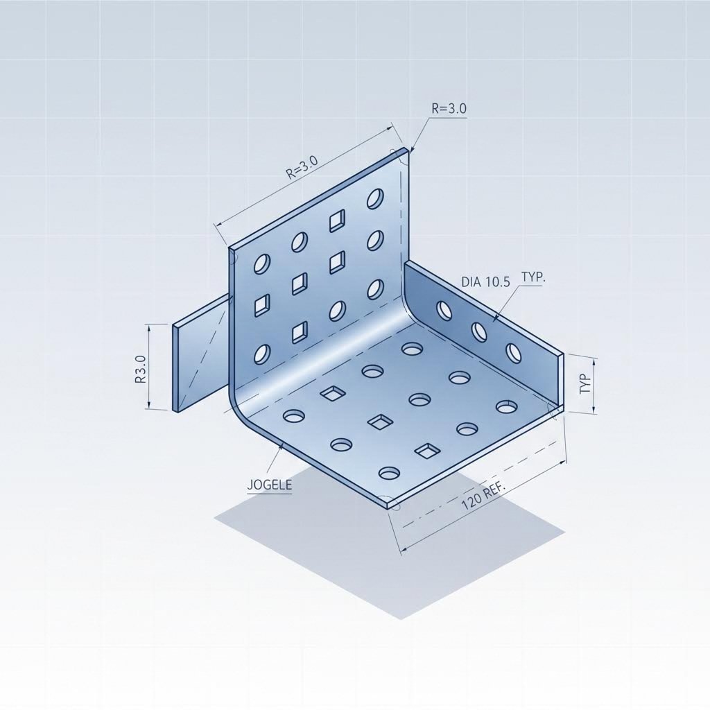
Hole and Feature Placement Guidelines
Holes seem straightforward until they deform during bending, crack near edges, or break your punch tooling. Proper metal fabrication design requires understanding the relationship between feature geometry and material behavior.
Start with hole diameter. According to Procurabl's design guidelines, hole diameters should be greater than the sheet thickness. Smaller holes increase punch loading, create excessive burrs, and wear tooling faster. The practical minimum? Match hole diameter to material thickness as an absolute floor.
Spacing matters just as much as size. Follow these distance rules to prevent deformation and maintain structural integrity:
- Hole-to-edge distance - Minimum 1.5× material thickness from any edge
- Hole-to-hole spacing - Minimum 2× material thickness between holes
- Hole-to-bend distance - Minimum 2.5× thickness plus the bend radius from any bend line
Why the extra distance from bends? When you place a hole too close to a future bend, the forming operation distorts it - elongating round holes into ovals and shifting their position. This is particularly critical for assembly holes that must align with mating components.
For slots, notches, and tabs, similar principles apply with slightly different specifics:
- Slot width - Minimum 1× material thickness
- Slot-to-edge distance - Minimum 2× material thickness
- Tab width - Minimum 2× material thickness to prevent tearing during forming
Extruded holes, louvers, and other features requiring more material deformation need even greater clearances from bends and edges - typically 3× thickness or more depending on feature depth.
Optimizing Designs for Production
Smart sheet metal design guide principles go beyond individual feature rules. The best designs consider how parts nest on raw material, how they'll be held during processing, and how assembly complexity affects total cost.
Grain direction matters more than you think. Sheet metal arrives with a rolling direction from the mill, creating directional properties that affect bend quality. As noted in the Five Flute guide, aligning bend lines perpendicular to grain direction - especially with less ductile metals like 6061-T6 - prevents cracking and weakness at bends. This constraint must be balanced against nesting efficiency.
Nesting optimization reduces material cost. When laying out your sheet metal fabrication techniques, consider how multiple parts will fit on a standard sheet. Irregular shapes with protruding tabs waste material between parts. Designing for efficient nesting - even if it means minor geometry adjustments - can reduce material consumption by 10-20%.
Stiffening features add strength without thickness. Rather than specifying heavier gauge material, consider these techniques to improve rigidity:
- Beads - Rolled or drawn ridges that increase section modulus and resist drumhead vibration
- Embosses - Raised features created by stretching the material (limit depth to 3× thickness to prevent tearing)
- Corner ribs - V-notched features perpendicular to bends that dramatically increase local stiffness
- Hems - Folded edges that double material thickness locally while improving safety and aesthetics
Design for coating and finishing. If your parts require powder coating, anodizing, or other surface treatments, account for dimensional changes. Parts must be held during coating - meaning some area will remain uncoated. Specify this location on your drawings so it appears in a non-critical area.
Simplify assembly through self-locating features. Using tabs, slots, and embossed dimples that align components automatically eliminates fixture costs and reduces assembly time. Where possible, use PEM inserts or rivets instead of welding - the time and cost savings are substantial when functionality permits.
The cumulative effect of good DFM is striking. According to industry analysis, addressing manufacturability during design - rather than correcting it after release - reduces engineering change orders by 50% or more. Parts flow through production faster, quality improves, and per-unit costs drop.
With your designs optimized for production, understanding how these principles apply across different industries reveals why sheet metal remains the manufacturing method of choice for countless applications.
Industry Applications and Real-World Use Cases
Now that you understand the materials, processes, and design principles - where does all this sheet metal fabrication actually end up? The answer might surprise you. From the car you drive to the smartphone in your pocket, sheet metal components are everywhere - often performing critical functions you never notice until something fails.
What makes the sheet metal manufacturing industry so pervasive? It's the unique combination of strength, formability, and cost-effectiveness that no other manufacturing method matches at scale. Let's explore how different sectors leverage these advantages to solve real engineering challenges.
Automotive and Transportation Applications
The automotive industry consumes more sheet metal than any other sector - and for good reason. Every vehicle rolling off assembly lines contains hundreds of stamped, formed, and welded components working together to protect passengers, reduce weight, and meet increasingly stringent performance standards.
According to Enze Manufacturing's automotive fabrication guide, the primary applications include:
- Body panels - Doors, hoods, fenders, and roof panels formed through deep drawing and stamping operations. These require excellent surface quality for paint adhesion and precise dimensional control for gap consistency.
- Chassis and structural components - Frame rails, cross members, and reinforcements that define vehicle crash performance. High-strength steel sheet forming creates complex geometries while meeting strict weight targets.
- Suspension components - Control arms, brackets, and mounting plates that must withstand cyclic loading throughout the vehicle's life.
- Engine and drivetrain components - Heat shields, valve covers, and transmission cases where thermal management meets structural requirements.
Why does sheet metal dominate automotive metal parts manufacturing? The answer lies in volume economics and material efficiency. Stamping operations can produce body panels in seconds, with material utilization rates exceeding 70% through optimized nesting. No other process delivers comparable precision at automotive production volumes.
For manufacturers serving automotive OEMs, quality certifications matter enormously. Companies like Shaoyi (Ningbo) Metal Technology demonstrate this with IATF 16949 certification - the automotive industry's gold standard that validates advanced process control for chassis, suspension, and structural components. This certification ensures suppliers maintain the statistical process control, traceability, and continuous improvement systems that automotive programs demand.
Electronics and Enclosure Manufacturing
Open any computer, server rack, or telecommunications cabinet and you'll find sheet metal enclosures performing multiple critical functions simultaneously. According to Approved Sheet Metal's engineering guide, fabricated enclosures protect sensitive electronics while managing heat, shielding electromagnetic interference, and enabling serviceability.
The sheet metal industry serves electronics applications through:
- Computer and server enclosures - Precision-formed housings with integrated ventilation, cable management, and mounting provisions. Aluminum and galvanized steel dominate for their balance of weight, EMI shielding, and corrosion resistance.
- Control panel compartments - Industrial automation relies on sheet metal enclosures rated for specific ingress protection (IP) levels. IP65 enclosures resist dust ingress and water jets; IP67 handles temporary submersion.
- Telecommunications cabinets - Outdoor-rated enclosures protecting network equipment from weather, vandalism, and thermal extremes. These often require NEMA 4X ratings for corrosion resistance in harsh environments.
- Medical equipment housings - Stainless steel enclosures meeting sterility requirements and ISO 13485 standards for medical device manufacturing.
Sheet metal engineering for enclosures involves more than just forming a box. Designers must consider:
- EMI/RFI shielding - Conductive metals like aluminum naturally block electromagnetic interference, with conductive gaskets sealing seams for enhanced protection
- Thermal management - Louvers, perforations, and strategic ventilation prevent component overheating while maintaining protection ratings
- Serviceability - Removable panels, hinged doors, and self-locating hardware enable maintenance access without specialized tools
The flexibility of steel sheet fabrication allows complete customization - from silk-screened branding to color-matched powder coating that elevates product aesthetics.
Construction and Architectural Uses
Walk through any commercial building and sheet metal is literally all around you - in the walls, ceiling, and especially the mechanical systems keeping occupants comfortable. Construction applications leverage sheet metal's durability, weather resistance, and cost-effectiveness for both structural and finishing applications.
According to industry analysis, construction depends on metal fabrication manufacturing for:
- HVAC ductwork - Galvanized steel ducts distribute conditioned air throughout buildings. The material's corrosion resistance, formability into complex transitions, and ability to withstand temperature cycling make it ideal for air handling systems.
- Roofing and cladding - Standing seam metal roofs, wall panels, and rain screen systems combine weather protection with architectural expression. Aluminum and coated steel provide decades of service with minimal maintenance.
- Structural framing - Cold-formed steel studs and joists offer consistent dimensions, termite immunity, and non-combustibility for commercial and residential construction.
- Architectural elements - Decorative panels, column covers, ceiling systems, and custom metalwork where copper's developing patina or stainless steel's brightness becomes part of the design language.
The renewable energy sector represents a growing construction application. Solar panel frames, wind turbine nacelle enclosures, and battery storage containers all rely on sheet metal components engineered for decades of outdoor exposure.
Aerospace and Defense Applications
When weight directly translates to fuel consumption and payload capacity, aerospace applications push sheet metal fabrication to its limits. Aircraft skins, structural brackets, and avionics enclosures demand the tightest tolerances and most rigorous quality standards in manufacturing.
Key aerospace applications include:
- Fuselage skins - Stretch-formed aluminum panels creating the aerodynamic exterior surface
- Wing structures - Ribs, spars, and skin panels balancing strength with weight minimization
- Avionics housings - EMI-shielded enclosures protecting sensitive electronics from harsh operating conditions
- Engine components - Heat shields and nacelle structures withstanding extreme thermal environments
AS9100 certification validates manufacturers' capability to meet aerospace quality requirements - ensuring traceability, configuration control, and process discipline throughout production.
Appliance and Consumer Products
From refrigerators to washing machines, household appliances demonstrate sheet metal's versatility in consumer applications. The combination of structural cabinets, cosmetic exterior panels, and functional internal components showcases the full range of fabrication techniques.
- Appliance housings - Painted steel or stainless steel exteriors providing durability and aesthetic appeal
- Internal structures - Brackets, mounting frames, and reinforcements supporting mechanical systems
- Functional components - Dryer drums, oven cavities, and dishwasher tubs engineered for specific operating conditions
Mass production economics drive these applications. Progressive die stamping produces millions of identical components with per-piece costs measured in cents - economics impossible to achieve with any alternative process at comparable volumes.
Why Sheet Metal Remains the Preferred Choice
Across all these industries, sheet metal production offers advantages that alternative manufacturing methods simply can't match:
| Advantage | Why It Matters |
|---|---|
| Strength-to-weight ratio | Formed shapes add stiffness without adding mass |
| Volume scalability | Per-piece costs decrease dramatically at higher quantities |
| Material efficiency | Nesting optimization minimizes waste compared to subtractive processes |
| Design flexibility | Complex geometries achievable through standard forming operations |
| Finishing options | Powder coating, plating, and anodizing enable functional and aesthetic customization |
Understanding these industry-specific requirements helps you select the right production approach for your project - whether you're developing a prototype or planning high-volume production runs.
Choosing the Right Production Approach for Your Project
You've designed your component, selected materials, and understand the forming processes - but here's the question that separates successful projects from budget disasters: Is sheet metal even the right manufacturing method for your application? Sometimes it absolutely is. Other times, CNC machining, 3D printing, or die casting delivers better results at lower total cost.
Making this decision correctly requires understanding what is sheet metal fabrication compared to alternatives - and knowing exactly when each approach makes economic and technical sense. The sheet metal fabrication process excels in specific scenarios, but forcing it into applications where other methods perform better wastes both time and money.
Prototyping to Production Transition
Here's where many projects stumble: the approach that works brilliantly for prototypes often fails spectacularly at production volumes - and vice versa. Understanding how different sheet metal fabrication processes scale prevents costly pivots mid-project.
Prototyping priorities focus on speed, flexibility, and design validation. You need parts fast, in small quantities, with the ability to iterate rapidly. At this stage:
- 3D printing delivers complex geometries in days without tooling investment
- CNC machining produces precise metal parts from solid stock with no forming tooling
- Laser-cut and bent sheet metal offers production-representative parts quickly
Production priorities shift dramatically toward per-piece cost, consistency, and throughput. Tooling investments that seemed prohibitive at 10 units become trivial when spread across 10,000. According to HIPP's custom parts manufacturing guide, production manufacturing focuses on repeatability, quality consistency, and cost optimization for larger volumes - fundamentally different requirements than prototype manufacturing.
The transition challenge? Many engineers design for prototyping convenience, then discover their geometry requires expensive modifications for production tooling. A bracket that CNC machines beautifully may have features impossible to stamp efficiently.
Modern manufacturers bridge this gap through integrated capabilities. For example, Shaoyi (Ningbo) Metal Technology demonstrates this approach with 5-day rapid prototyping that transitions directly to automated mass production - ensuring prototype parts accurately represent production characteristics from the start. Their comprehensive DFM support and 12-hour quote turnaround help engineers identify production constraints during design rather than after tooling commitments.
Volume Considerations and Cost Factors
The economics of manufacturing follow predictable patterns once you understand the underlying cost drivers. Every process has fixed costs (tooling, programming, setup) and variable costs (material, labor, machine time per part). The relationship between these determines your optimal manufacturing method.
Consider how costs break down across sheet metal fabrication processes and alternatives:
| Manufacturing Method | Tooling/Setup Cost | Per-Part Cost (Low Volume) | Per-Part Cost (High Volume) | Volume Sweet Spot |
|---|---|---|---|---|
| 3D Printing (Metal) | Minimal ($0-500) | $50-500+ | $50-500+ | 1-50 units |
| CNC Machining | Low ($500-2,000) | $20-200 | $15-150 | 10-500 units |
| Sheet Metal (No Hard Tooling) | Low ($200-1,500) | $10-100 | $5-50 | 50-5,000 units |
| Sheet Metal (Progressive Die) | High ($10,000-100,000+) | Prohibitive | $0.50-5 | 10,000+ units |
| Die Casting | Very High ($15,000-150,000+) | Prohibitive | $1-10 | 10,000+ units |
Notice the crossover points. A part costing $20 each via CNC machining at 100 units might cost $2 each via progressive die stamping at 50,000 units - but only after absorbing $40,000 in tooling. At 100 units, that stamping approach would yield $402 per part (tooling amortized). The math doesn't lie.
According to Modus Advanced's DFM research, minimizing part counts dramatically affects manufacturing economics. A part costing $20.00 per unit at 100 units can drop to $2.00 per unit at 5,000 units due to volume economies. This principle applies across all manufacturing methods but impacts tooling-intensive processes like stamping most dramatically.
Beyond direct part costs, consider these hidden factors:
- Lead time costs - Fast delivery commands premium pricing; standard lead times reduce costs 15-30%
- Inventory carrying costs - Large batch production ties up capital in finished goods
- Quality costs - Higher-volume processes typically achieve better consistency once optimized
- Engineering change costs - Hard tooling makes design changes expensive; soft tooling offers flexibility
When to Choose Sheet Metal Over Alternatives
So when does the sheet metal manufacturing process win? Understanding the comparative advantages helps you make confident decisions.
Choose sheet metal production when:
- You need thin-walled enclosures, brackets, or structural components
- Production volumes exceed 50-100 units (or will eventually)
- Weight matters - formed shapes offer excellent strength-to-weight ratios
- Material efficiency is important - cutting and forming wastes less than machining from solid
- You require large flat surfaces with formed features
- Standard sheet gauges (0.5-6mm) meet your thickness requirements
Choose CNC machining when:
- Parts require tight tolerances throughout (±0.025mm or better)
- Complex 3D geometries can't be formed from flat sheets
- You need thick sections or solid cross-sections
- Quantities remain under 100-500 units
- Material options extend beyond formable sheet metals
According to Protocase's enclosure comparison guide, CNC machined enclosures excel for high-end electronics and precision instruments due to their high-quality finish and ability to work with specialized materials. However, they may not be as cost-effective as finished sheet metal for standard applications.
Choose 3D printing when:
- Geometries are impossible to form or machine conventionally
- You need parts in days, not weeks
- Quantities stay under 50 units
- Internal lattice structures or organic shapes are required
- You're iterating designs rapidly during development
Choose die casting when:
- Complex 3D shapes exceed sheet metal forming capabilities
- Production volumes justify tooling investment (typically 10,000+ units)
- Integrated features (bosses, ribs, mounting provisions) reduce assembly
- Aluminum or zinc alloys meet material requirements
As the Protocase analysis notes, die casting offers superior protection against impact and harsh environments, making it ideal for automotive electronics and industrial control systems - but limited design flexibility can present hurdles when aiming for intricate shapes.
Comparing Manufacturing Methods: The Decision Matrix
The following table consolidates selection criteria to guide your metal form decision:
| Criteria | Sheet Metal | CNC Machining | 3D Printing | Die Casting |
|---|---|---|---|---|
| Typical Lead Time | 1-3 weeks | 1-2 weeks | 3-7 days | 6-12 weeks (tooling) |
| Minimum Order Quantity | 1 unit | 1 unit | 1 unit | 100-1,000 units typical |
| Design Flexibility | High (soft tooling) | Very High | Highest | Low (hard tooling) |
| Best Tolerance | ±0.1mm | ±0.025mm | ±0.1-0.3mm | ±0.1mm |
| Material Efficiency | 70-85% | 20-50% | 90%+ | 95%+ |
| Wall Thickness Range | 0.5-6mm typical | 0.5mm+ (limited by rigidity) | 0.4mm+ | 1-4mm typical |
When evaluating plate fabrication and sheet metal alternatives, ask yourself these qualifying questions:
- What are my realistic volume projections over the product lifecycle?
- How likely are design changes after initial production?
- What tolerances are functionally necessary versus specified out of habit?
- Does my timeline allow for tooling development?
- What matters more - unit cost or total program cost?
The best manufacturing decision considers not just today's requirements, but your product's entire lifecycle. A process that seems expensive at prototype volumes may deliver massive savings at scale - or vice versa.
Selecting the right production partner matters as much as selecting the right process. Look for manufacturers offering comprehensive DFM support who can identify potential issues before production begins, rapid quoting to keep your development timeline moving, and demonstrated quality certifications relevant to your industry. For automotive applications, IATF 16949 certification validates a manufacturer's capability to meet the industry's demanding requirements for statistical process control and continuous improvement.
The sheet metal production secrets we've covered throughout this guide - from material selection and forming processes through quality standards and DFM guidelines - ultimately serve one purpose: helping you get better parts, faster, at lower total cost. Apply these principles systematically, and you'll consistently outperform engineers who treat manufacturing as an afterthought.
Frequently Asked Questions About Sheet Metal Production
1. What is sheet metal fabrication and how does it work?
Sheet metal fabrication transforms flat metal sheets (typically 0.5mm to 6mm thick) into functional components through three core process categories: cutting operations (laser, plasma, waterjet, punching), forming processes (bending, stamping, deep drawing, roll forming), and assembly techniques (welding, riveting, fastening). The process begins with material selection based on application requirements, followed by CNC-controlled cutting to create blanks, then forming operations that plastically deform the material into desired shapes. Modern fabrication integrates computer numerical control throughout, enabling tolerances as tight as ±0.05mm on laser-cut features and consistent quality across production runs.
2. Is sheet metal fabrication a good trade?
Sheet metal fabrication offers a rewarding career path with diverse opportunities. The trade encompasses technical skills from precision forming and welding to CNC programming and quality control. Experienced sheet metal workers can advance to specialized roles like foreman positions earning $57,000-$77,000 annually, or transition into engineering and supervisory roles. The industry serves automotive, aerospace, electronics, and construction sectors, providing job stability and variety. As manufacturing becomes increasingly automated, workers who combine traditional skills with CNC proficiency and quality certification knowledge (like IATF 16949 requirements) find the strongest career prospects.
3. What materials are commonly used in sheet metal production?
The primary sheet metal materials include aluminum alloys (6061 being most common), cold-rolled steel, stainless steel (304 and 316 grades), galvanized steel, and copper. Aluminum offers excellent strength-to-weight ratio and natural corrosion resistance, ideal for aerospace and electronics. Cold-rolled steel provides high strength at the lowest cost for automotive and structural applications but requires coating for corrosion protection. Stainless steel delivers superior corrosion resistance for medical, food processing, and marine environments. Material selection depends on formability requirements, corrosion resistance needs, strength specifications, weight constraints, and budget considerations.
4. What are the most common sheet metal forming processes?
The five primary forming processes are bending (using press brakes for angular shapes), stamping (progressive dies for complex flat or shallow parts at high volumes), deep drawing (creating cup or box shapes from flat blanks), roll forming (continuous profiles for structural sections), and stretch forming (large curved panels for aerospace). Each process has specific applications: bending suits brackets and enclosures, stamping dominates automotive body panel production, deep drawing creates cylindrical containers, roll forming produces architectural trim and structural rails, and stretch forming minimizes springback on aircraft skins. Process selection depends on part geometry, material properties, tolerance requirements, and production volume.
5. How do I choose between sheet metal fabrication and other manufacturing methods?
Choose sheet metal production when you need thin-walled enclosures or structural components, production volumes exceed 50-100 units, weight optimization matters, and standard gauges (0.5-6mm) meet thickness requirements. CNC machining works better for parts requiring ±0.025mm tolerances, complex 3D geometries, or quantities under 500 units. 3D printing suits rapid prototyping with quantities under 50 units and impossible-to-form geometries. Die casting becomes economical above 10,000 units for complex shapes requiring integrated features. Consider total lifecycle costs including tooling amortization, lead times, design change flexibility, and quality consistency when making your decision.