 Small batches, high standards. Our rapid prototyping service makes validation faster and easier —

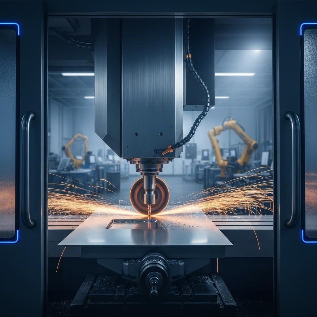
Machining Sheet Metal Vs Laser Cutting: When Each Method Wins
Understanding Machining Sheet Metal as a Distinct Process
When you hear "sheet metal work," you probably picture bending, folding, and welding flat metal sheets into enclosures or brackets. But what happens when your project demands precision features that traditional fabrication simply cannot deliver? That's where machining sheet metal enters the picture as a powerful alternative.
Many engineers struggle with the choice between fabrication vs manufacturing approaches, often treating them as entirely separate worlds. The reality? These disciplines complement each other beautifully when you understand their distinct strengths. Let's break down what makes machining thin materials a game-changer for precision applications.
What Sets Machining Apart from Fabrication
Traditional sheet metal fabrication transforms flat metal sheets through cutting, bending, and joining techniques. Think of it as shaping and assembling. Machining and fabrication, however, follow fundamentally different principles.
Machining sheet metal is a subtractive manufacturing process that removes material from thin metal stock using CNC-controlled cutting tools to achieve precision features, tight tolerances, and complex geometries impossible through forming alone.
Here's the key distinction: fabrication shapes material without necessarily removing it, while machining carves away material to create exact specifications. When your design calls for threaded holes, precision pockets, or features requiring tolerances within microns, you're looking at a machining application rather than a fabrication job.
Consider the fabrication variations available in a typical shop: laser cutting profiles, press brake bending, and welding assemblies. These processes excel at creating structural components quickly and cost-effectively. However, they hit limitations when you need dimensional accuracy that only subtractive CNC processes can deliver.
The Precision Advantage of CNC on Thin Materials
Why would you machine a thin sheet instead of simply cutting and forming it? The answer lies in what happens after the basic shape exists.
Imagine a fabricated electronics enclosure that needs precisely positioned mounting holes for circuit boards. Stamping or punching might get you close, but CNC machining achieves hole positions accurate to thousandths of an inch. For aerospace brackets or medical device housings, this precision isn't optional; it's essential.
When comparing fabricate vs manufacture approaches, consider these scenarios where machining wins:
- Integrated features like heat sinks, gaskets, or precision pockets for electronics
- Threaded holes requiring exact positioning and depth control
- Complex 3D geometries that forming cannot achieve
- Surface finishes demanding tighter quality standards
The fabrication and machining relationship works best when viewed as complementary rather than competitive. A stamped bracket might need secondary machining for critical mounting surfaces. A laser-cut panel might require precision boring for bearing fits. Understanding when each process excels helps you make smarter manufacturing decisions.
Throughout this guide, you'll discover exactly when machining sheet metal outperforms cutting methods like laser, waterjet, or plasma. You'll also learn how combining both disciplines delivers results neither can achieve alone. The goal isn't choosing sides; it's choosing wisely based on your specific requirements.
Core Machining Methods Applied to Sheet Metal
Now that you understand what sets this subtractive process apart from traditional fabrication, let's explore the specific techniques that make precision metal machining possible on thin materials. Three primary methods dominate the landscape: milling, drilling, and turning. Each brings unique capabilities to sheet metal applications, yet most resources fail to explain how these processes adapt for thinner stock.
When you're working with metal machining on sheets rather than solid blocks, the approach changes significantly. The workpiece is thinner, more flexible, and responds differently to cutting forces. Understanding these distinctions helps you select the right method for your project.
Milling Operations for Sheet Metal Features
Milling metal stands as the most versatile method for adding precision features to sheet stock. Using rotary cutters controlled by CNC programming, milling removes material to create complex 3D shapes, pockets, slots, and contours that forming simply cannot achieve.
Think about an aluminum electronics enclosure that needs integrated heat sink fins machined directly into the surface. Or consider a stainless steel bracket requiring precise pockets for component clearance. These are classic milling applications where cnc milling metals delivers results impossible through stamping or bending alone.
What makes milling particularly valuable for thin materials? The ability to control depth precisely. When machining a pocket into 0.125-inch aluminum sheet, you might remove material to within 0.020 inches of the opposite surface. This demands exceptional control over cutting depth, tool engagement, and feed rates.
According to Protocase's CNC milling specifications, 5-axis machinery can accommodate sheet metal parts up to 42" x 24" x 20", while 3-axis machines handle parts up to 25.75" x 15.75". This capacity covers most enclosure and bracket applications where precision features must be added after initial forming.
Corner radii represent a critical consideration when milling pockets into sheet metal. Smaller radii require smaller tools that cut slower and wear faster. Larger radii allow bigger, faster tools that reduce machining time and cost. The inverse relationship between corner radius and achievable depth also matters; smaller tools typically work only for shallower features.
Drilling and Secondary Hole Operations
While laser cutting creates holes quickly, drilling and tapping deliver something cutting cannot: precision hole geometry with threads. When your metal machining parts require exact hole positions, controlled depths, or threaded features, drilling operations become essential.
Stamped or punched holes often exhibit slight taper, burrs, or positional variation. CNC drilling eliminates these issues, placing holes exactly where your design specifies with consistent diameter throughout. For applications demanding bearing fits or precision dowel locations, this accuracy isn't optional.
Drilling also enables:
- Counterbored holes for flush fastener heads
- Countersunk features for flat-head screws
- Tapped threads with controlled depth and pitch
- Reamed holes for exact diametrical tolerance
Turning, the third primary method, sees less frequent use in sheet metal applications since it's designed for cylindrical parts. However, turning operations can create precision bushings or sleeves from sheet stock rolled into tubes, or machine flanges on formed cylindrical components.
Tolerance Capabilities Across Methods
Here's where cnc machining metal truly separates itself from cutting-only approaches. The achievable tolerances determine whether your parts fit, function, and perform as designed.
| Method | Sheet Metal Application | Typical Tolerance Achievable | Best Use Case |
|---|---|---|---|
| CNC Milling | Pockets, slots, contours, surface features | ±0.005" (0.13mm) standard; ±0.001" (0.025mm) premium; ±0.0001" (0.0025mm) ultra precision | Complex 3D geometry, integrated features, precision pockets for electronics |
| CNC Drilling | Precision holes, threaded features, counterbores | ±0.005" (0.13mm) standard positioning; tighter with reaming | Critical mounting holes, bearing fits, threaded assemblies |
| CNC Turning | Cylindrical features, bushings, flanges | ±0.005" (0.13mm) standard; ±0.001" (0.025mm) premium | Rolled tube components, precision cylindrical inserts |
These tolerance values, based on Protocase's published specifications, demonstrate the precision gap between machining and typical fabrication processes. Standard precision already exceeds what stamping or laser cutting typically achieves, while premium and ultra precision options serve demanding aerospace and medical applications.
Surface finish quality also distinguishes machined features. A standard machined surface achieves 125 RA roughness, smooth enough for most functional applications. Finer finishes require additional operations but remain achievable when specifications demand them.
Understanding these capabilities helps you specify the right process for each feature on your parts. Sometimes standard precision suffices; other times, your design demands ultra-precision tolerances that only dedicated machining can deliver. The next section explores what happens when you apply these methods to thin, flexible materials and the unique challenges that arise.
Overcoming Challenges When Machining Thin Materials
You've selected the right machining method and understand the tolerances achievable. But here's where reality gets complicated: thin sheet materials don't behave like solid blocks. They flex, vibrate, and distort in ways that can ruin precision features in seconds. If you've ever watched a thin aluminum sheet lift off the machine table mid-cut, you know exactly what we're talking about.
Sheet metal machining presents unique obstacles that traditional machining metalworking approaches weren't designed to handle. The same flexibility that makes sheet metal easy to form becomes your biggest enemy when trying to hold tight tolerances. Let's explore these challenges and, more importantly, the solutions that experienced machinists rely on.
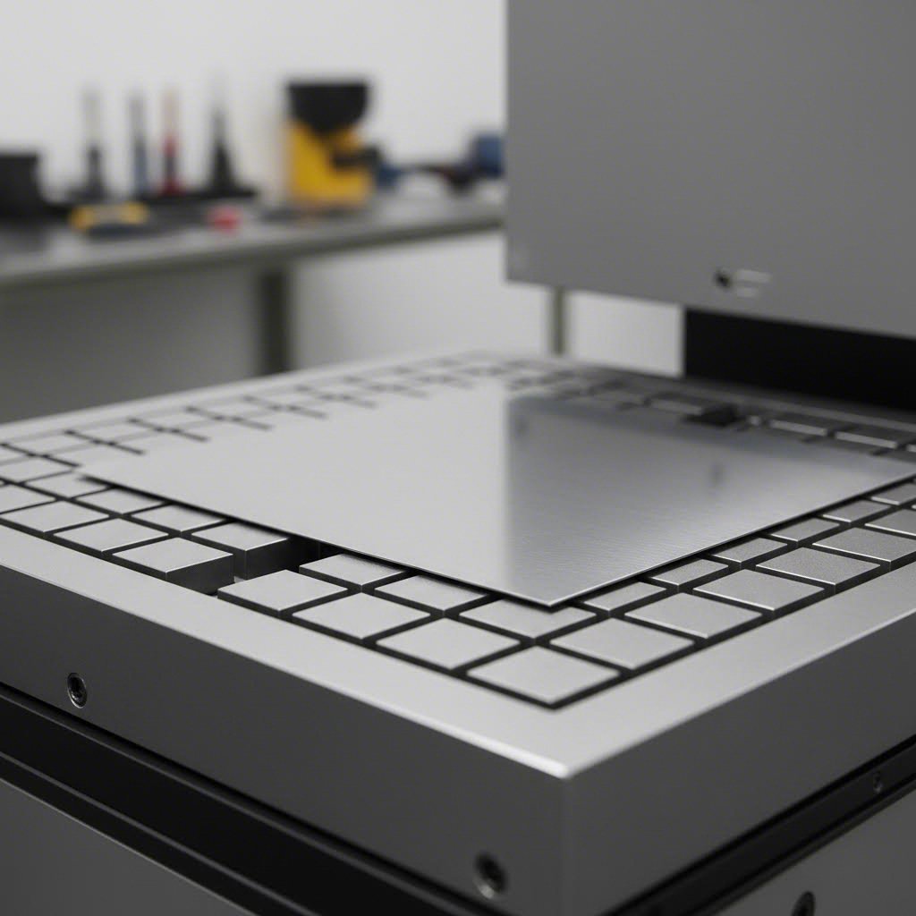
Solving the Workholding Puzzle for Thin Materials
Imagine trying to machine a precise pocket into a 0.060-inch aluminum sheet. The moment your end mill engages, cutting forces want to pull that material upward. Traditional edge clamping? According to DATRON's technical documentation, thin sheets are inherently less rigid, making edge clamping nearly impossible since securing the perimeter with mechanical clamps often results in the sheet lifting or shifting during machining.
The problem compounds when you consider that operators often run machines at slower speeds to compensate, sacrificing productivity just to maintain stability. Custom clamping solutions like toe clamps require time-consuming setup and removal, adding costs and extending cycle times.
So what actually works? Here are the proven fixturing solutions for holding thin materials during machining:
- Vacuum tables: These aluminum chucks feature a grid of grooves connected to vacuum pumps, holding sheets quickly and firmly across the entire surface. As Mekanika explains, vacuum tables operate by leveraging the pressure differential between vacuum beneath the workpiece and atmospheric pressure above, generating consistent hold-down force without external clamps.
- Sacrificial backing plates: Placing a permeable material layer between the vacuum chuck and your sheet allows complete cut-through operations. DATRON's advanced vacuum table systems use specialized permeable stock with low-tack adhesive, providing extra grip for small parts without leaving residue.
- Magnetic chucks: For ferrous materials like steel and stainless, magnetic workholding provides uniform holding force across the entire sheet surface without mechanical interference.
- Custom soft jaws: When edge clamping is unavoidable, soft jaws machined to match your workpiece contour distribute pressure evenly, minimizing deformation at clamping points.
The sheet metal CNC machine setup you choose depends on your specific application. Vacuum systems excel for nonferrous materials when using mist coolant or ethanol-based systems. However, they typically won't work with flood coolant, which can compromise the vacuum seal.
Managing Heat and Preventing Distortion
Workholding solves only half the puzzle. Even perfectly secured thin materials face another enemy: heat. When cutting tools engage metal, friction generates thermal energy. In thick parts, this heat dissipates through the surrounding material. In thin sheets? That heat has nowhere to go, causing localized expansion that warps your precision features.
According to Makera's research on thin-walled machining, heat management significantly impacts distortion control in metal parts machining. The thermal expansion and contraction cycle during cutting creates internal stresses that manifest as warping, twisting, and dimensional inaccuracy.
Effective thermal management strategies include:
- Mist cooling systems: Deliver coolant precisely to the cutting zone without flooding the work surface, maintaining vacuum seal integrity while extracting heat.
- Directed air jets: Provide cooling without liquid, ideal for applications where moisture is problematic.
- Strategic coolant application: Target coolant at the tool-material interface rather than flooding the entire workpiece, preventing thermal shock while maintaining temperature stability.
Beyond cooling, your cutting parameters directly influence heat generation. Machined metal parts from thin stock require a gentler approach than solid block machining. Employ shallow cut depths, slower feed rates, and lighter passes to reduce pressure on thin materials. This approach minimizes localized stress while promoting stability and accuracy.
Controlling Vibration for Surface Quality
The third challenge rarely discussed in competitor content: vibration. Thin materials act like drumheads, amplifying any oscillation from the cutting process. This vibration degrades surface finish, accelerates tool wear, and can cause catastrophic chatter that ruins parts.
Sharp, high-quality tools minimize cutting forces, reducing vibration at the source. Ensure your tooling is well-maintained and designed to distribute cutting forces evenly across the material surface. Dull tools require more force to cut, generating more vibration and heat simultaneously.
The order of machining operations also influences vibration and part stability. Start with roughing cuts to remove the majority of material, allowing internal stresses to relax. Follow with finishing cuts using reduced depths and feeds to achieve precise dimensions without exciting vibration modes in the remaining thin material.
Advanced sheet metal CNC machine setups incorporate adaptive machining technology that uses real-time sensors to monitor vibration and cutting forces. This feedback automatically adjusts tool paths, cutting speeds, and feed rates during the process, effectively reducing distortion before it escalates into significant problems.
Mastering these challenges transforms sheet metal machining from frustrating to predictable. With proper workholding, thermal management, and vibration control, you'll achieve the precision tolerances discussed earlier. But these techniques must adapt to different materials, which behave differently under cutting forces. The next section explores material-specific strategies that optimize results for aluminum, steel, stainless, and more.
Material-Specific Machining Strategies for Sheet Metals
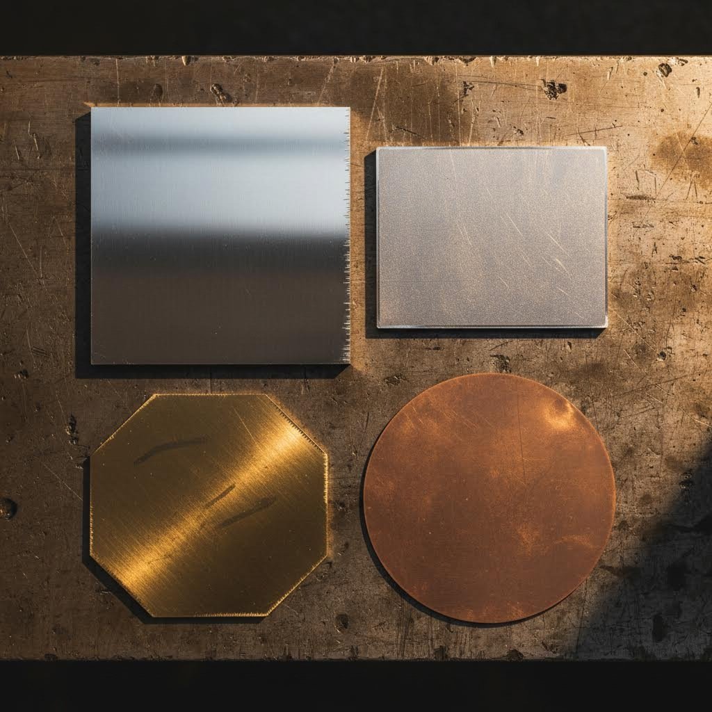
You've mastered workholding, heat management, and vibration control. But here's the thing: those techniques must adapt dramatically depending on which metal sits on your machine table. Aluminum behaves nothing like stainless steel. Copper demands completely different tooling than brass. Each material brings unique machining metals challenges that generic advice simply doesn't address.
The gap in most manufacturing resources? They treat all sheet metals identically or offer vague guidance that doesn't help when you're setting up an actual job. Let's fix that with material-by-material strategies based on real-world performance data and machining metal parts across thousands of production runs.
Aluminum and Soft Alloy Considerations
Aluminum ranks among the easiest metals to machine, making it a favorite for prototyping and high-volume production alike. Its high machinability rating means faster cutting speeds, longer tool life, and reduced cycle times compared to harder materials. Sounds perfect, right?
Not so fast. Aluminum's softness creates a frustrating problem: built-up edge. The material tends to gum up on cutting tools, welding itself to the tool's cutting edge and degrading surface finish. Left unchecked, this buildup causes tool deflection, dimensional inaccuracy, and eventually tool failure.
The solution lies in tool selection and cutting parameters:
- Sharp, polished flutes: Choose uncoated carbide tools with highly polished cutting surfaces that resist material adhesion.
- High cutting speeds: Faster spindle speeds generate enough heat to keep chips flowing rather than sticking. Target 400-600 surface feet per minute for most aluminum alloys.
- Adequate chip clearance: Use 2-3 flute end mills with aggressive helix angles (around 40°) that evacuate chips quickly from the cutting zone.
- Appropriate coolant: Mist coolant or ethanol-based systems work excellently with vacuum workholding setups common in sheet aluminum machining.
According to industry machinability data from Machining Doctor, aluminum alloys typically rate around 70% on standardized machinability scales when compared to free-machining brass. This high rating translates to approximately 2-3 times faster material removal rates than stainless steel, dramatically reducing production costs for machining line steel alternatives.
Surface finishes on aluminum sheet typically achieve Ra 0.8-1.6 μm with standard tooling and proper parameters. For applications requiring smoother finishes, light finishing passes with reduced feed rates push roughness values below Ra 0.4 μm without secondary polishing.
Machining Stainless and Hardened Steels
Stainless steel represents the opposite end of the machining spectrum. Where aluminum forgives mistakes, stainless punishes them. The material's tendency to work-harden means inconsistent cutting creates progressively harder surfaces that destroy tools and ruin tolerances.
Work hardening occurs when the cutting tool rubs against the material rather than cleanly shearing it. Each pass that doesn't remove sufficient material cold-works the surface, increasing hardness until subsequent passes become impossible. This phenomenon demands consistent chip load—you must remove material with every revolution rather than allowing the tool to dwell or skip.
Steel CNC machining on thin sheets compounds these challenges. The workpiece has limited mass to absorb cutting forces and dissipate heat, making thermal management critical. Key strategies include:
- Maintain consistent chip load: Never let your tool rub. Program feed rates that ensure material removal on every tooth engagement.
- Use appropriate cutting speeds: Stainless requires significantly slower speeds than aluminum—typically 50-100 surface feet per minute depending on the specific alloy.
- Select proper tool coatings: Unlike aluminum where uncoated tools excel, stainless benefits from TiAlN or AlCrN coatings that resist heat and reduce friction.
- Apply generous coolant: High-pressure coolant directed at the cutting zone helps clear chips and manage the significant heat generated.
Carbon and alloy steels generally machine more predictably than stainless grades, though they still require attention to heat management. The cnc forming operations that precede machining can introduce residual stresses in steel sheets, potentially causing distortion during material removal. Stress-relief annealing before precision machining eliminates this variable for critical tolerance applications.
Copper and Brass: Sharp Tools and Proper Parameters
Copper and brass share excellent thermal and electrical conductivity, making them essential for electronics, connectors, and heat-transfer applications. Their machining behavior differs significantly despite their similar appearance.
Copper's extreme ductility creates smearing problems. The material tends to flow around cutting edges rather than shearing cleanly, leaving poor surface finishes and requiring frequent tool changes. Sharp tooling isn't optional—it's mandatory. Dull edges turn copper machining into a frustrating exercise in surface defects and dimensional variability.
Brass, particularly free-machining grades like C360, represents the gold standard for machinability. According to Tirapid's brass machining guide, C360 brass carries a 100% baseline machinability rating—the benchmark against which other metals are measured. This rating reflects several advantages:
- Cutting speeds of 400-600 SFM enable rapid material removal
- Tool life extends 30-50% compared to harder materials
- Surface finishes of Ra 0.4-1.6 μm are achievable with standard tooling
- Metal removal rates run 2-3× higher than stainless steel
The lead content in free-machining brass (2.5-3% in C360) acts as an internal lubricant, breaking chips effectively and reducing cutting forces. For applications requiring lead-free materials, grades like C260 offer excellent formability but somewhat reduced machinability, requiring adjusted parameters and expectations.
Brass machining benefits from uncoated carbide tools with 10-20° positive rake angles. Higher rake angles than used for steel help the material shear cleanly rather than deform. Feed rates typically run 0.03-0.08 mm/rev for finishing operations, with roughing passes reaching 0.08-0.20 mm/rev depending on depth of cut and tool diameter.
Material Comparison for Machining Sheet Metals
Understanding how these materials compare helps you set appropriate expectations and plan efficient machining operations. The following table summarizes key considerations for each common sheet metal type:
| Material | Machinability Rating | Key Challenges | Recommended Approach | Surface Finish Achievable |
|---|---|---|---|---|
| Aluminum (6061, 7075) | ~70% (vs. brass baseline) | Built-up edge, material gumming on tooling | High speeds (400-600 SFM), polished uncoated carbide, 2-3 flute tools with aggressive chip evacuation | Ra 0.4-1.6 μm |
| Carbon Steel (1018, 1045) | ~65-75% | Heat generation, potential work hardening, residual stress from cnc forming | Moderate speeds (100-200 SFM), coated carbide tools, consistent chip load, adequate coolant | Ra 0.8-3.2 μm |
| Stainless Steel (304, 316) | ~45-50% | Severe work hardening, high heat, tool wear | Lower speeds (50-100 SFM), TiAlN coated tools, never let tool rub, high-pressure coolant | Ra 0.8-3.2 μm |
| Copper (C110, C101) | ~60% | Smearing, material flow around cutting edge, poor chip breaking | Very sharp uncoated carbide, high positive rake angles, moderate speeds, mist cooling | Ra 0.8-2.4 μm |
| Brass (C360, C260) | 100% (baseline standard) | Minimal—primarily burr formation at edges | High speeds (400-600 SFM), sharp uncoated carbide, 10-20° positive rake, light finishing passes | Ra 0.4-1.6 μm |
These values represent typical performance with proper tooling and parameters. Actual results vary based on specific alloy grades, sheet thickness, feature complexity, and machine capability. Use this table as a starting point, then adjust based on your specific application requirements.
Notice how dramatically machining approaches differ between materials. The same cutting parameters that produce excellent results in brass would destroy tools instantly in stainless steel. Conversely, the slow, careful approach required for stainless would waste time and money on aluminum or brass jobs.
Armed with material-specific strategies, you're ready to make informed decisions about when machining delivers superior results compared to laser cutting, waterjet, or other methods. The next section explores that critical comparison, helping you choose the right approach for each project.
Choosing Between Machining and Cutting Methods
You've optimized your material-specific approach. Your workholding strategy is dialed in. But before you start any job, there's a fundamental question: should you machine this part, or would laser cutting, waterjet, or plasma get you there faster and cheaper?
Here's the honest truth that most manufacturing guides skip: cnc sheet metal cutting and machining aren't competitors—they're teammates. Each method dominates different scenarios. Choosing wrong means wasting money on precision you don't need or settling for quality that doesn't meet specifications. Let's break down exactly when each approach wins.
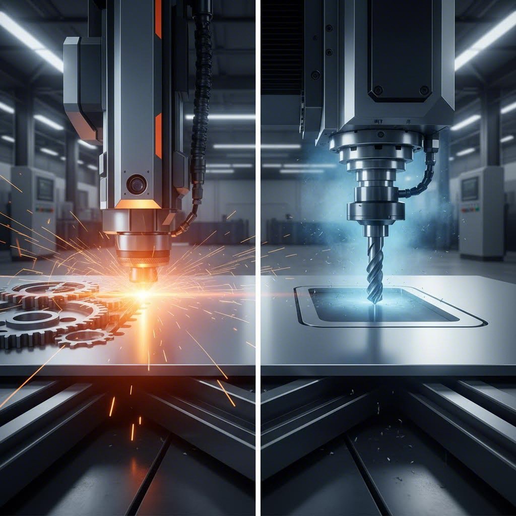
When CNC Machining Outperforms Cutting Methods
Think about what cutting methods actually do. Laser cutting, waterjet, and plasma all slice through material along a 2D path. They create profiles, holes, and exterior shapes with impressive speed. But here's what they cannot do: create 3D features, precision pockets, or controlled-depth geometry.
When does cnc sheet metal machining become the clear winner? Consider these scenarios:
- Precision holes requiring exact diameter: Laser and waterjet create holes, but with taper and heat-affected zones. Machining delivers cylindrical holes within thousandths of an inch.
- Threaded features: No cutting method creates threads. If your design needs tapped holes, machining is mandatory.
- Pockets and recesses: Need a controlled-depth pocket for component clearance? Cutting methods only go through—machining goes to exact depth.
- Tight positional tolerances: According to Makera's technical comparison, CNC milling achieves minimum tolerances of ±0.01 mm, making it suitable for applications where exact measurement is crucial.
- Complex 3D geometry: Contoured surfaces, angled features, and multi-level designs require subtractive machining approaches.
The sheet metal cnc approach also excels when surface finish matters. Blue Elephant's manufacturing research confirms that laser cutting can produce smooth edges, but machining offers more control over final surface quality—particularly important for sealing surfaces, bearing interfaces, or aesthetic requirements.
Imagine designing an electronics enclosure. Laser cutting creates the flat blank quickly. But those precision mounting holes for circuit boards? The counterbored clearances for fastener heads? The threaded standoffs for assembly? Those features demand machining operations that cutting simply cannot replicate.
Cost and Speed Tradeoffs to Consider
Now for the other side of the equation. Machining delivers superior precision, but it comes with tradeoffs you need to understand before committing.
Speed represents the most significant difference. When comparing fabrication vs machining approaches, laser cutting moves through thin materials at remarkable rates. According to industry data from Makera's manufacturing analysis, laser cutting is generally faster, particularly when working with thin materials or intricate designs. The laser can cut or engrave at high speeds, making it suitable for high-volume productions or projects with tight turnarounds.
CNC machining, by contrast, removes material piece by piece—a more time-consuming process, especially for harder or thicker materials. This speed difference translates directly to cost. Simple 2D profiles cut faster and cheaper with laser or waterjet than with machining operations.
Equipment costs also factor into your decision. Laser cutters typically require less initial investment and offer lower operating costs for straightforward cutting applications. However, when your project demands the precision and capability of a cnc machine sheet metal setup, the investment delivers value through capabilities cutting cannot match.
Here's a practical decision framework:
- Choose cutting methods when you need 2D profiles, simple hole patterns, and speed matters more than ultra-tight tolerances.
- Choose machining when specifications demand precision features, 3D geometry, threads, or controlled-depth operations.
- Combine both when your design includes simple profiles (cut first) plus precision features (machine second).
Method Comparison for Sheet Metal Applications
Understanding the technical capabilities of each method helps you match the right process to your requirements. This comparison covers the key performance factors that influence your decision:
| Factor | CNC Machining | Laser Cutting | Waterjet | Plasma Cutting |
|---|---|---|---|---|
| Tolerance | ±0.001" to ±0.005" (±0.025mm to ±0.13mm) | ±0.005" to ±0.010" (±0.13mm to ±0.25mm) | ±0.005" to ±0.015" (±0.13mm to ±0.38mm) | ±0.020" to ±0.030" (±0.5mm to ±0.76mm) |
| Edge Quality | Excellent; controlled surface finish achievable | Very good; minimal burring on most materials | Good; slight taper possible on thick materials | Fair; requires secondary finishing for precision |
| Material Thickness Range | 0.010" to 2"+ depending on machine capacity | 0.001" to 1" (varies by laser power and material) | 0.010" to 6"+ (virtually unlimited with proper equipment) | 0.030" to 2" (optimal range for cost efficiency) |
| Speed | Slower; material removed incrementally | Fast for thin materials and intricate patterns | Moderate; slower than laser for thin stock | Very fast for thick materials |
| Best Applications | Precision features, 3D geometry, threads, pockets, tight-tolerance holes | 2D profiles, intricate patterns, high-volume thin sheet cutting | Heat-sensitive materials, thick stock, mixed material cutting | Heavy plate, structural steel, cost-sensitive thick cutting |
Notice how each method occupies a distinct niche. Plasma excels at thick plate work where precision matters less than speed and cost. Waterjet handles materials that cannot tolerate heat—critical for certain alloys and composites. Laser cutting dominates high-volume thin sheet applications where intricate profiles justify the equipment investment.
Sheet metal cnc machining fills the precision gap none of these cutting methods can address. When your application demands tolerances in the ±0.001" range, controlled surface finishes, or features beyond 2D profiles, machining becomes not just preferable but necessary.
Making Your Decision
The right choice depends on your specific project requirements. Ask yourself these questions:
- Does my design include 3D features, pockets, or controlled-depth geometry? → Machining required
- Do I need threaded holes or precision bore diameters? → Machining required
- Are my tolerance requirements tighter than ±0.005"? → Machining preferred
- Is this primarily a 2D profile with standard hole patterns? → Cutting methods likely sufficient
- Does speed and cost outweigh precision requirements? → Consider cutting first, machining for critical features only
Many successful manufacturing operations combine both approaches. A laser-cut blank provides the basic shape quickly and cost-effectively. Secondary machining then adds the precision features that differentiate a good part from a great one. This hybrid approach delivers the best of both worlds—cutting speed where it matters, machining precision where it counts.
Understanding when each method wins positions you to make smarter manufacturing decisions. But the real power comes from combining these processes strategically, which is exactly what the next section explores.
Integrating Machining with Sheet Metal Fabrication
Here's a manufacturing secret that separates good engineers from great ones: you don't have to choose between stamping speed and machining precision. The most efficient production strategies combine both processes, leveraging each method's strengths while minimizing their limitations.
Think about it. Stamping and forming operations produce parts at incredible rates—sometimes hundreds per minute. But those stamped parts often need additional features that forming simply cannot deliver. Precision holes for bearing fits. Threaded bosses for assembly. Tight-tolerance surfaces for sealing. This is where metal fabrication and machining become inseparable partners rather than competing alternatives.
The hybrid approach transforms how manufacturers think about sheet metal fabrication and assembly. Instead of forcing one process to do everything poorly, you let each process do what it does best. The result? Better parts, faster delivery, and lower total costs than either method alone.
Secondary Operations That Transform Fabricated Parts
Imagine a stamped automotive bracket fresh off the progressive die. The basic shape is perfect—formed in milliseconds with excellent repeatability. But look closer at those mounting holes. They're punched, which means slight taper, potential burrs, and positional accuracy limited to what the die allows. For non-critical applications, that's perfectly acceptable.
But what happens when that bracket mounts a safety-critical sensor? Suddenly, those punched holes need to become precision features. That's where secondary machining operations step in to bridge the gap between fabrication speed and machining accuracy.
According to Metco Fourslide's manufacturing documentation, stamped metal parts typically undergo secondary processes after initial forming. These operations include drilling or tapping, CNC machining, grinding, and heat treating—transforming good fabricated parts into precision components.
Common secondary machining operations that add value to fabricated sheet metal include:
- Precision boring: Enlarges punched or laser-cut holes to exact diameters with controlled cylindricity, essential for bearing fits and dowel locations.
- Thread milling: Creates internal or external threads with precise pitch and depth control, enabling direct fastener assembly without additional hardware.
- Surface finishing: Machines flat reference surfaces to tight flatness tolerances for sealing, mating, or measurement datum requirements.
- Feature locating: Adds precision reference features that position the part accurately in subsequent assembly or inspection operations.
- Counterboring and countersinking: Creates recessed features for flush-mounted fasteners that stamping cannot produce.
- Reaming: Achieves hole diameters within thousandths of an inch for interference or precision slip fits.
The machining and manufacturing integration doesn't just add features—it elevates the entire part to a higher performance tier. A stamped bracket becomes a precision mounting platform. A formed enclosure becomes a sealed housing. The base fabrication provides 80% of the part's value; secondary machining delivers the remaining 20% that makes the difference between acceptable and exceptional.
Combining Stamping Speed with Machining Precision
Why does this hybrid approach deliver better results than either process alone? Consider the economics and physics involved.
Stamping produces parts at 30-250 strokes per minute according to industry data from Metco Fourslide. At those speeds, tooling costs amortize quickly across high volumes, driving per-part costs remarkably low. Trying to achieve similar production rates with machining alone? Impossible for most geometries.
Conversely, trying to stamp precision features directly runs into fundamental limitations. Die tolerances, material springback, and process variation all conspire against tight-tolerance punched features. You could invest in extraordinarily expensive precision dies—or you could stamp close and machine to final specification at a fraction of the tooling cost.
Recent advances in hybrid processing demonstrate dramatic improvements over traditional separated operations. According to Hotean's technical research, integrated stamping and CNC workflows achieve burr reduction from 0.1mm to 0.02mm while delivering 60% faster cycle times compared to separate stamping and deburring operations. The same study documented 15% material savings through improved nesting optimization when both operations are planned together.
The automotive and aerospace industries rely heavily on this machining fabrication strategy. Consider these real-world scenarios:
- Automotive suspension brackets: Stamped for basic geometry and mounting points, then machined for precision bushing bores and alignment surfaces that ensure proper vehicle handling.
- Aerospace structural fittings: Formed from high-strength aluminum sheet, then machined for fastener holes requiring AS9100-compliant positional accuracy.
- Electronic enclosures: Fabricated through bending and welding, then machined for connector cutouts requiring exact positioning and thread features for grounding studs.
- Medical device housings: Stamped shells receiving secondary machining for instrument mounting surfaces demanding micron-level flatness.
The fabrication & machining combination proves especially valuable when part quantities fall in the middle ground—too high for pure machining economics, too precision-demanding for stamping alone. This sweet spot covers a surprising range of industrial applications where neither pure approach optimizes total cost and quality.
What makes this integration work seamlessly? Planning. When designers consider secondary machining from the start, they specify fabricated features with appropriate stock allowances for finish machining. They position precision requirements where machining access remains practical. They design datum features that transfer accurately from fabrication fixtures to machining setups.
The hybrid manufacturing approach isn't just about adding operations—it's about designing products and processes that leverage each method's strengths. As you'll see in the next section, specific industries have embraced this philosophy, demanding machined sheet metal components that neither pure fabrication nor pure machining could deliver alone.
Industry Applications Demanding Machined Sheet Metal
You've seen how hybrid manufacturing combines stamping speed with machining precision. But where does this approach matter most? Certain industries don't just prefer precision machining sheet metal—they require it. The stakes are too high, the tolerances too tight, and the consequences of failure too severe for anything less.
What connects aerospace brackets, medical device housings, automotive structural components, and electronics enclosures? Each demands the unique combination of sheet metal's weight efficiency with machining's dimensional accuracy. These industries have discovered that the manufacturing of metal parts at this performance level requires both disciplines working together.
Aerospace and Defense Applications
In aerospace, every gram matters. Sheet metal's exceptional strength-to-weight ratio makes it indispensable for aircraft structures. But aerospace also demands tolerances that basic fabrication cannot deliver. According to Neway Precision's aerospace documentation, precision sheet metal fabrication supports the structural and electronic integrity of aircraft, satellites, and UAV systems, with parts meeting exacting standards in flatness, form accuracy, and surface finish.
Consider what happens when a navigation housing requires EMI shielding with ±0.02 mm flatness. Or when a mounting bracket must position sensors with micron-level accuracy while surviving vibration profiles that would destroy lesser components. These applications demand metal machined to specifications that forming alone cannot achieve.
Fabrication engineering in aerospace has evolved to embrace the hybrid approach. Components are often formed first for basic geometry, then machined for critical features that affect system performance. The result? Parts that meet airworthiness standards while optimizing weight and manufacturability.
Common aerospace applications requiring machined sheet metal include:
- Avionics enclosures: EMI-shielded housings for flight computers, radar interfaces, and communication systems requiring precision cutouts and threaded mounting features
- Structural mounting brackets: Lightweight aluminum and stainless steel brackets machined for exact fastener hole positions and bearing surface flatness
- Thermal and RF shielding panels: Heat deflection panels and isolation baffles with machined ventilation patterns and precise edge geometry
- Sensor mounting plates: Precision surfaces that maintain dimensional stability under extreme temperature cycling and altitude profiles
- UAV navigation housings: Integrated enclosures combining formed shapes with machined features for antenna placement and cable routing
The machining of metal parts for aerospace follows strict quality protocols. AWS D17.1 welding standards, AS9102 first-article inspection requirements, and geometric dimensioning and tolerancing (GD&T) specifications govern every component. Tolerance requirements typically demand flatness, perpendicularity, and hole position accuracy within ±0.05 mm or better—precision that only secondary machining can guarantee after initial forming.
Automotive Precision Component Requirements
Automotive manufacturing operates at volumes that dwarf other industries. Stamping lines produce millions of brackets, panels, and structural components annually. Yet even with this emphasis on speed, precision requirements continue tightening as vehicles become more sophisticated.
Modern vehicles integrate advanced driver assistance systems, electric powertrains, and complex sensor arrays. Each of these technologies demands mounting surfaces and interface features that exceed traditional stamping capabilities. The solution? Secondary machining operations that transform stamped components into precision assemblies.
Suspension components illustrate this perfectly. A stamped control arm provides the basic structural form at high speed and low cost. But the bushing bores that determine handling characteristics? Those require machined precision to ensure proper alignment and ride quality. The same principle applies across chassis, powertrain, and body systems.
Key automotive applications demanding machined sheet metal include:
- Suspension brackets and mounts: Stamped structures with machined bushing bores, alignment surfaces, and precision fastener locations
- Sensor mounting platforms: Brackets requiring exact positioning for cameras, radar, and lidar systems critical to ADAS functionality
- Electric vehicle battery enclosures: Formed housings with machined sealing surfaces and precision mounting points for thermal management components
- Powertrain mounting brackets: Structural components machined for vibration isolation mount positioning and reference datum surfaces
- Structural reinforcements: High-strength steel components combining formed geometry with machined interface features
Quality certifications like IATF 16949 govern automotive sheet metal production, requiring statistical process control and traceability that integrated fabrication-to-machining workflows support. The combination of stamping efficiency with machining precision enables manufacturers to meet both cost targets and performance specifications.
Electronics and Medical Device Requirements
Electronics enclosures present unique challenges that fabrication engineering must address. Printed circuit boards require mounting holes positioned within thousandths of an inch. Connector cutouts demand exact dimensions for proper mating. EMI shielding effectiveness depends on tight-fitting joints that only machined features can achieve.
When you design an enclosure for sensitive electronics, you're balancing thermal management, electromagnetic compatibility, and mechanical protection. Sheet metal provides excellent shielding and heat dissipation. Machining adds the precision features that ensure everything fits and functions correctly.
The medical device industry takes precision requirements even further. According to Prototek's industry analysis, sheet metal fabrication in the medical industry creates essential parts and devices—from surgical instruments to equipment housings—that are crucial for patient care. The materials must be biocompatible, corrosion-resistant, and capable of withstanding repeated sterilization.
Medical applications demanding machined sheet metal include:
- Surgical instrument housings: Stainless steel enclosures machined for exact component positioning and sterilization compatibility
- Diagnostic equipment panels: Precision surfaces for sensor mounting and display integration
- Imaging system components: Aluminum structures combining light weight with dimensional stability under thermal cycling
- Patient monitoring enclosures: Housings requiring machined features for cable management and user interface elements
These industries share a common thread: they demand what neither pure fabrication nor pure machining delivers alone. The weight efficiency of sheet metal combined with the dimensional accuracy of CNC operations creates components that meet performance specifications while optimizing cost and manufacturability. Finding a manufacturing partner capable of both disciplines becomes essential for success in these demanding applications.
Selecting the Right Partner for Precision Sheet Metal Projects
You've mastered the technical decisions: when to machine versus cut, which materials require special handling, and how hybrid manufacturing delivers superior results. But here's the final piece that determines whether your project succeeds or stumbles: choosing a manufacturing partner who can actually execute your vision.
The difference between manufacturing vs fabrication capabilities matters less than finding a partner who masters both. When you're sourcing precision sheet metal components, splitting work between a fabrication shop and a machine shop creates handoff headaches, quality inconsistencies, and extended lead times. The smartest approach? Partner with a single source that integrates cnc metal fabrication with precision machining under one roof.
What to Look for in a Manufacturing Partner
Imagine sending your stamped brackets to one vendor, then shipping them across town for secondary machining, then back again for finishing. Each transfer introduces delays, potential damage, and communication gaps. Now imagine a partner who handles everything—from initial prototyping through production machining—without your parts ever leaving their facility.
That integrated capability transforms your supply chain. According to Modus Advanced's manufacturing research, vertical integration represents a partner's ability to handle multiple processes in-house rather than outsourcing to subcontractors, delivering streamlined communication, consistent quality control, and reduced logistics complexity.
When evaluating potential partners for machine fabrication projects, prioritize these essential qualifications:
- IATF 16949 or equivalent quality certifications: This automotive-specific quality management system, built on ISO 9001 foundations, signals commitment to consistency, safety, and defect prevention. According to Xometry's certification guide, IATF 16949 certification proves a company's ability and commitment to limit defects while reducing waste—exactly what precision sheet metal projects demand.
- Comprehensive DFM support capabilities: Partners with engineering resources on staff catch design issues before they become production problems. Look for teams that actively improve designs rather than simply executing drawings.
- Rapid prototyping services: According to Protolabs' prototyping guide, prototyping enables you to explore different design options without committing to costly tooling too early. Partners offering quick-turn prototypes accelerate your development cycle.
- Integrated fabrication-to-machining workflows: Single-source partners eliminate the coordination burden of managing multiple suppliers, reducing lead times and quality risks.
- Engineering staff accessibility: Direct access to engineers who understand both cnc sheet metal fabrication and precision machining ensures technical discussions happen without filters or delays.
Consider Shaoyi (Ningbo) Metal Technology as an example of this integrated approach. Their IATF 16949-certified operations combine custom metal stamping with precision machining capabilities, offering 5-day rapid prototyping and 12-hour quote turnaround. This type of comprehensive DFM support and vertically integrated manufacturing eliminates the supplier coordination challenges that plague multi-vendor strategies.
Streamlining Your Supply Chain
Understanding the difference between manufacturing and fabrication helps you ask better questions when evaluating partners. Fabrication of metal transforms raw sheets into formed shapes. Manufacturing adds the precision features and quality systems that turn those shapes into functional components. The best partners excel at both.
What questions should you ask potential cnc metal partners?
- Can you handle both initial forming and secondary precision machining in-house?
- What certifications validate your quality management systems?
- How quickly can you turn around prototypes for design validation?
- Do you provide DFM feedback during the quoting process?
- What's your typical lead time from approved design to production parts?
- How do your engineering teams interface with customers during production?
Partners who answer these questions confidently—with specific examples and documented capabilities—demonstrate the integrated expertise your precision sheet metal projects require.
The hybrid manufacturing approach you've learned throughout this guide demands partners who understand both disciplines deeply. When stamped brackets need precision boring, when formed enclosures require threaded features, when laser-cut blanks demand tight-tolerance machining—you need a manufacturing partner who sees these as unified processes rather than separate specialties.
Your supply chain simplifies dramatically when a single qualified partner handles the complete journey from flat sheet to finished precision component. That's the competitive advantage that integrated manufacturing delivers: faster timelines, consistent quality, and engineering expertise available whenever you need it.
Frequently Asked Questions About Machining Sheet Metal
1. Is sheet metal cheaper than machining?
Sheet metal fabrication typically costs less at volumes above 50-100 units due to faster processing speeds. CNC machining remains more expensive regardless of quantity but delivers tighter tolerances (±0.001" vs ±0.005") and 3D features impossible through cutting alone. For precision holes, threads, and pockets, machining justifies the higher cost. Many manufacturers combine both approaches—laser cutting blanks quickly, then machining only critical features—to optimize total project costs.
2. Can CNC machines cut sheet metal?
Yes, CNC machines cut sheet metal through milling, drilling, and routing operations. Unlike laser or waterjet cutting that follows 2D profiles, CNC machining removes material to create 3D features like precision pockets, counterbores, and threaded holes. CNC milling achieves tolerances of ±0.001" and controlled-depth geometry that cutting methods cannot replicate. For thin materials, vacuum tables and sacrificial backing plates secure the workpiece during machining operations.
3. What are common sheet metal cutting mistakes?
Common mistakes include inadequate cutting parameters causing heat buildup and distortion, insufficient workholding that allows thin sheets to lift during machining, ignoring material-specific requirements (stainless steel work-hardens without consistent chip load), and poor tool maintenance leading to smearing on soft metals like copper. Using edge clamping instead of vacuum tables creates instability. Always match cutting speeds, coolant application, and tooling to your specific material type.
4. What is the difference between sheet metal fabrication and CNC machining?
Sheet metal fabrication shapes flat metal through bending, cutting, and forming without necessarily removing material. CNC machining is a subtractive process that removes material to achieve precision features and tight tolerances. Fabrication excels at creating basic shapes quickly at high volumes, while machining adds threaded holes, precision pockets, and features requiring tolerances within microns. Many projects combine both—stamping for speed, machining for precision.
5. When should I choose machining over laser cutting for sheet metal?
Choose machining when your design requires threaded features, precision holes with controlled diameters, 3D pockets or recesses, tolerances tighter than ±0.005", or controlled-depth geometry. Laser cutting works best for 2D profiles, intricate patterns, and high-volume thin sheet cutting where speed matters more than ultra-tight precision. For electronics enclosures needing exact mounting hole positions or aerospace brackets requiring bearing-fit bores, machining delivers results cutting cannot match.