 Small batches, high standards. Our rapid prototyping service makes validation faster and easier —

Sheet Metal Press Die Secrets: From Raw Design To Flawless Parts
What Is a Sheet Metal Press Die and How Does It Work
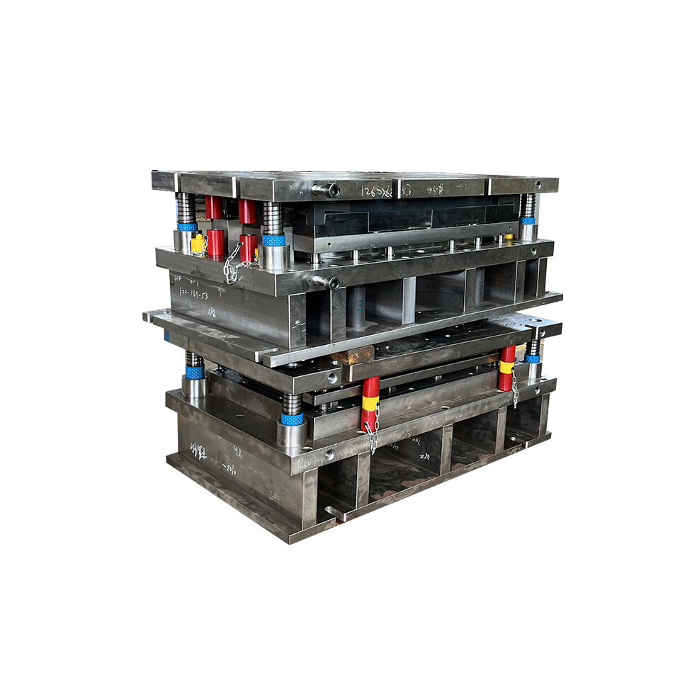
Imagine producing thousands of identical metal components, each matching the last with precision measured in microns. That's exactly what a sheet metal press die makes possible. At its core, this specialized tool transforms flat metal sheets into complex three-dimensional parts through carefully controlled force application. Whether you're examining an automobile door panel, an aircraft bracket, or the casing of your smartphone, you're looking at the work of precision press and die systems.
A sheet metal press die functions as a matched set of hardened steel tools mounted in a press machine. When the press applies force, typically ranging from a few tons to thousands of tons, the die tool cuts, bends, or forms the metal sheet into a predetermined shape. This process occurs in fractions of a second, enabling manufacturers to produce components at rates that would be impossible with manual fabrication methods.
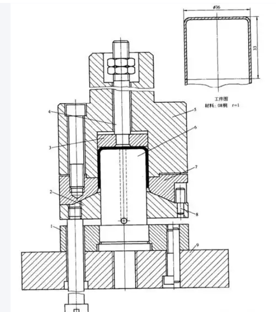
The Anatomy of a Press Die System
Understanding how a press die works starts with recognizing its fundamental components. According to tooling experts at Moeller Precision Tool, a die set consists of several essential elements working in precise coordination:
- Die Plates (Shoes): These serve as the foundation where other components mount. Typically made from steel or aluminum alloys, they hold everything in proper alignment.
- Punch: The upper moving component that applies force directly to the sheet metal, either cutting through it or pressing it into the die cavity below.
- Die Block: The lower stationary component featuring a cavity or cutting edge that works in opposition to the punch.
- Guide Pins and Bushings: Manufactured to tolerances within 0.0001 inches, these ensure the upper and lower die plates align with exceptional accuracy.
- Die Springs: High-force compression springs that hold metal sheets in place during forming operations.
- Retainers: Components that secure punches and die buttons in their precise positions.
The relationship between punch and die is critical. In cutting operations, the punch nose is slightly smaller than the die opening, typically offset by 5-10% of the material thickness. This calculated gap, called the "die break," allows clean shearing action when the punch descends through the sheet metal.
Why Precision Tooling Drives Modern Manufacturing
Metal presses equipped with precision dies have become indispensable across virtually every manufacturing sector. In automotive production, these tools stamp out body panels, structural components, and countless brackets. Aerospace manufacturers rely on them for lightweight aluminum and titanium parts. Electronics companies use miniature die systems to create connector pins and shielding components measured in millimeters.
Press dies enable mass production of identical parts with micron-level precision, transforming raw sheet metal into functional components at speeds and consistency levels that no other manufacturing method can match.
The steel press operations that shape modern products depend entirely on this precision. When a die is properly designed and maintained, it can produce hundreds of thousands of parts before requiring service. Each component emerges virtually identical to the last, meeting tolerances that might specify dimensions within a few thousandths of an inch.
What makes the sheet metal press so valuable isn't just speed; it's the combination of repeatability, material efficiency, and cost-effectiveness at scale. Once a die is built and validated, the cost per part drops dramatically compared to machining or manual fabrication. This economic advantage explains why stamping remains the preferred method for high-volume metal component production across industries worldwide.
Essential Types of Sheet Metal Press Dies Explained
Now that you understand how a press die system works, the next question becomes: which type do you actually need? Selecting the right die tooling isn't just a technical decision—it directly impacts your production speed, part quality, and bottom line. Yet most resources barely scratch the surface when explaining the differences between die types. Let's change that by diving deep into the four major categories you'll encounter.
Each set of die serves a distinct purpose, and understanding these differences helps you match tooling to your specific manufacturing requirements. Whether you're stamping simple washers or complex automotive brackets, there's an optimal die press configuration for your application.
| Die Type | Working Principle | Best Applications | Complexity Level | Production Volume Suitability |
|---|---|---|---|---|
| Progressive Dies | Metal strip advances through multiple stations; each station performs a specific operation sequentially | Small to medium parts with multiple features; electrical connectors, brackets, clips | High (requires precise strip feeding and station alignment) | High-volume production (100,000+ parts) |
| Transfer Dies | Individual blanks are mechanically transferred between separate die stations | Larger parts requiring complex forming; deep-drawn components, structural parts | Very High (requires sophisticated transfer mechanisms) | Medium to high volume; flexible for varying runs |
| Compound Dies | Multiple cutting operations occur simultaneously in a single press stroke | Flat parts requiring precise edges; washers, gaskets, simple blanks | Moderate (simpler than progressive but requires precision) | Medium to high volume for simple geometries |
| Combination Dies | Both cutting and forming operations execute in one stroke | Parts needing both blanking and bending; formed brackets, shaped components | Moderate to High (combines multiple operation types) | Medium volume with mixed operation requirements |
Progressive vs Transfer Die Systems
When you need high-speed production of complex parts, progressive and transfer press dies represent your two primary options. But they work in fundamentally different ways, and choosing incorrectly can cost you significant time and money.
Progressive dies operate like an assembly line compressed into a single tool. A continuous metal strip feeds through the die, advancing a precise distance with each press stroke. At each station along the strip, a different operation occurs—punching a hole here, forming a bend there, trimming an edge at the next position. According to manufacturing specialists at Eigen Engineering, this approach delivers exceptional repeatability and enables the production of complex components quickly and affordably.
The press die set in a progressive system typically includes:
- Multiple punch and die stations arranged in sequence
- Pilot pins that locate the strip precisely at each station
- Carrier strips that connect partially completed parts until final separation
- Automatic feeding mechanisms that advance material consistently
Transfer dies take a different approach. Rather than keeping parts connected to a strip, they work with discrete blanks that mechanical fingers or robots move between stations. This method, as noted by Worthy Hardware, offers more flexibility in part handling and orientation, making it ideal for larger, more intricate designs.
When should you choose one over the other? Progressive dies excel when you're producing smaller parts in extremely high volumes—think electrical terminals or small brackets where speed is paramount. Transfer dies become the better choice for larger components that require significant forming depth or complex three-dimensional shapes that wouldn't work well attached to a carrier strip. Hydraulic press dies often power these transfer systems due to the substantial forces required for deep drawing operations.
Choosing Between Compound and Combination Dies
Here's where terminology often creates confusion. Compound dies and combination dies sound similar, but they serve distinctly different purposes in die tooling applications.
Compound dies perform multiple cutting operations simultaneously. Imagine blanking out a washer shape while simultaneously piercing the center hole—all in one press stroke. This approach delivers exceptional precision because all cutting edges engage the material at the same moment, eliminating the alignment variations that can occur with sequential operations. For flat parts requiring tight tolerances on both inner and outer profiles, compound dies are often the optimal choice.
The precision advantage of compound dies becomes clear when you consider the mathematics. When cutting operations happen separately, each stroke introduces its own minor positioning variations. Compound dies eliminate this stacking of tolerances by completing all cuts in a single action. This principle applies similarly to coin press dies used in minting, where simultaneous operations ensure perfect registration between features.
Combination dies expand beyond cutting to include forming operations within that same single stroke. Need to blank a shape and immediately bend it? A combination die handles both. This approach reduces handling steps and can improve production rates for parts requiring both cutting and forming operations.
When does each type make sense for your press die set?
- Choose compound dies when: You're producing flat parts like washers, gaskets, or blanks where edge precision matters most and no forming is required
- Choose combination dies when: Your parts need both cutting and forming in a single operation, reducing material handling and improving cycle times
- Consider progressive dies instead when: Part complexity requires more than two or three operations, or when volume justifies the higher tooling investment
The cost implications differ significantly as well. Compound dies generally cost less than progressive systems due to their simpler construction. However, as industry analysis confirms, compound die stamping is more suited for simpler, flat parts and may not be economical when part geometry becomes complex. The right choice ultimately depends on balancing your part requirements, production volumes, and budget constraints.
Understanding these die categories positions you to have informed conversations with tooling suppliers and make decisions that optimize both quality and cost. But selecting the right die type is only part of the equation—the materials used to build that die, and the sheet metal you're forming, play equally critical roles in determining success.
Material Selection for Dies and Sheet Metal Workpieces
You've identified the right die type for your application. Now comes a decision that will determine whether your tooling lasts for 50,000 cycles or 500,000: material selection. This critical factor affects not just tool life, but also part quality, surface finish, and ultimately your cost per piece. Yet surprisingly, most resources skip over this topic entirely. Let's fix that gap.
The relationship between metal die construction and the sheet metal being formed creates a complex interplay. Choose die materials that are too soft, and you'll face premature wear. Select materials that are too hard without adequate toughness, and catastrophic cracking becomes a real risk. Understanding this balance separates successful stamping operations from those plagued by constant tooling problems.
Die Steel Selection for Maximum Tool Life
When building a sheet metal die, your steel selection directly impacts every aspect of production economics. According to research from AHSS Insights, tool and die wear occurs due to friction produced from contact between sheet metal and the tooling surface. The right die material resists this wear while maintaining the toughness needed to prevent cracking.
Most tooling dies for sheet metal forming fall into categories of cast iron, cast steel, or tool steels. Here's what you need to know about each:
- Cast Iron (G2500, G3500, D4512, D6510): Cost-effective for lower-volume applications and softer materials. Gray cast irons work well for prototype tooling, while pearlitic ductile irons offer improved durability for moderate production runs.
- D2 Tool Steel (SKD11, X153CrMoV12): The traditional workhorse for stamping dies. Offers good wear resistance at hardness levels of RC 58-60. However, as industry research confirms, D2 tools that last 50,000 cycles with conventional steels may fail after only 5,000-7,000 cycles when forming advanced high-strength steels.
- A2 and S7 Tool Steels: A2 provides balanced wear resistance and toughness, while S7 offers superior shock resistance for applications involving impact loading.
- Powder Metallurgy (PM) Tool Steels: These premium steel dies feature finer, more evenly distributed carbides than conventional tool steels. This microstructure delivers significantly higher impact strength—nearly 10x improvement in some cases—while maintaining hardness and wear resistance.
- Carbide Inserts: For extreme wear situations, tungsten carbide inserts at critical contact points extend die life substantially, though at higher initial cost.
The pressed sheet steel you're forming dramatically influences which die material performs best. When stamping mild steel or aluminum, conventional tool steels like D2 typically provide adequate service life. But switch to dual-phase steels with tensile strengths approaching 1000 MPa, and those same tools may fail prematurely through chipping, cracking, or excessive wear.
Surface Treatments That Extend Die Life
Beyond base material selection, surface treatments create a metal die set capable of withstanding demanding production conditions. These treatments add wear resistance without sacrificing the core toughness of the underlying steel.
Common surface treatment options include:
- Flame or Induction Hardening: Creates a hardened surface layer through localized heat treatment. Carbon content limits achievable hardness, and quenching introduces distortion risk.
- Nitriding: Diffuses nitrogen into the tool surface, creating exceptional hardness. Plasma (ion) nitriding processes faster than gas nitriding at lower temperatures, minimizing the brittle "white layer" formation.
- PVD Coatings (TiN, TiAlN, CrN): Physical vapor deposition applies thin, extremely hard coatings at temperatures that won't soften the underlying tool steel. Studies show PVD-coated cutting steels produce cleaner, more uniform edges after 200,000+ parts.
- CVD and TD Coatings: Chemical vapor deposition and thermal diffusion create stronger metallurgical bonds than PVD, but application temperatures around 1000°C may require subsequent rehardening.
The numbers tell a compelling story. According to tooling research, a chrome-plated tool failed after 50,000 parts, while an ion-nitrided tool with chromium nitride PVD coating produced more than 1.2 million parts. That's a 24x improvement in die life from proper surface treatment selection.
Matching Die Design to Your Sheet Metal Properties
Here's a reality many catalog pages won't tell you: the same die components that work perfectly with one material may fail catastrophically with another. Your sheet metal's properties dictate specific design requirements.
Thickness Considerations: Thinner materials require tighter clearances between punch and die. As sheet thickness increases, clearance percentages typically increase as well—ranging from 5% of material thickness for thin stock to 10% or more for heavier gauges. Getting this wrong leads to burr formation, excessive wear, or poor edge quality.
Material Hardness Effects: Softer metals like aluminum and copper alloys allow faster forming speeds and longer die life. Stainless steels and high-strength steels demand slower operations, increased clearances, and more robust tooling dies. Some advanced high-strength steel grades achieve hardness values approaching Rockwell C 57—nearly as hard as the tools forming them.
Different Metals, Different Demands:
- Aluminum Alloys: Prone to galling and adhesive wear. Polished die surfaces and appropriate coatings minimize material transfer. Wider clearances than steel prevent edge cracking.
- Stainless Steel: Work hardens significantly during forming, increasing demands on die materials. Expect higher forming forces and accelerated wear compared to carbon steel.
- High-Strength Steels (AHSS): These grades can reach hardness levels 4-5 times higher than mild steel. Standard die materials often prove inadequate. PM tool steels with advanced coatings become essential for acceptable tool life.
- Coated Steels: Galvanized and aluminum-silicon coated blanks interact differently with die surfaces. Research indicates ion nitrided coatings work best for galvanized steels, while PVD coatings excel with uncoated materials.
The relationship between material properties and die wear patterns follows predictable principles. Abrasive wear dominates when forming uncoated blanks that develop oxide scale. Adhesive wear and galling become primary concerns with coated materials where the coating tends to stick and transfer to die surfaces. Understanding your specific material's behavior guides both die material selection and maintenance planning.
Temperature adds another variable. Stamping operations generate heat through friction and plastic deformation. Research from Uddeholm demonstrates that die materials exposed to elevated temperatures can soften, losing both strength and wear resistance. This temper-back effect becomes especially critical in hot stamping applications where blank temperatures exceed 900°C.
With material selection principles established, the next logical step involves translating these considerations into actual die designs. Engineering fundamentals like clearance calculations, springback compensation, and tolerance specifications determine whether your carefully chosen materials deliver their full performance potential.
Die Design Principles and Engineering Fundamentals
You've selected your die type and chosen appropriate materials. Now comes the engineering work that separates functional tooling from problem-plagued dies. Understanding the principles behind clearance calculations, springback compensation, and tolerance specifications gives you the knowledge to evaluate designs critically and communicate effectively with die makers. Let's explore the engineering fundamentals that make forming dies actually work.
Every successful die for press applications begins with understanding why certain design choices matter—not just knowing what dimensions to specify. When you grasp these underlying principles, you can anticipate problems before they occur and make informed trade-offs between competing requirements.
Critical Clearance and Tolerance Calculations
The gap between punch and die—called clearance—might seem like a minor detail, but getting it wrong creates cascading quality problems. According to engineers at MISUMI, proper clearance ensures clean, precise cuts with minimal material deformation and residual burrs on cut edges.
So how do you determine the right clearance for your application? The calculation starts with understanding that clearance is specified as a percentage of material thickness per side. When someone mentions "10% clearance," they mean the gap on each side of the die hole equals 10% of your sheet metal thickness.
Here's the formula in action:
Clearance (per side) = Material Thickness × Clearance Percentage
For example, stamping 1.0mm mild steel with 10% recommended clearance gives you 0.1mm clearance on each side. The total die opening would be the punch diameter plus 0.2mm (clearance on both sides).
What determines the right percentage? Several factors come into play:
- Material Strength: Harder, stronger materials require increased clearance. Mild steel typically uses 5-10% clearance, while high-strength steels may need 10-15% or more.
- Material Thickness: Thicker stock generally requires proportionally larger clearances to prevent excessive tool stress.
- Edge Quality Requirements: Tighter clearances produce cleaner edges but accelerate tool wear. When a smooth edge matters most, you might accept faster wear rates.
- Tooling Life Priorities: Modern manufacturing research suggests that clearances of 11-20% can considerably reduce tooling strain and increase operational life, though at some cost to edge quality.
The consequences of incorrect clearance extend beyond part quality. Technical studies confirm that improperly specified clearances may lead to outright fracture of punch and die tooling, creating safety hazards for manufacturing personnel. Getting this right matters.
Tolerances throughout the die plate assembly demand similar attention. Die formed parts can only be as accurate as the tooling creating them. Guide pins and bushings typically hold tolerances within 0.0001 inches to maintain alignment between upper and lower die shoes. Punch and die button positioning requires equally tight control—small misalignments compound through thousands of cycles into significant quality drift.
Designing for Springback Compensation
Have you ever bent a piece of metal only to watch it partially unbend when you release pressure? That's springback, and it's one of the most challenging aspects of die design. As explained by engineers at Dahlstrom Roll Form, when metal is bent, the inner region is compressed while the outer region is stretched, creating internal stresses that make the metal want to return to its original shape.
Springback isn't a defect you can eliminate—it's physics. The key lies in understanding how to predict and compensate for it during die design.
What determines how much a part will spring back?
- Yield Point: This is the stress level where metal stops returning to its original shape. Higher yield strength materials exhibit more springback.
- Elastic Modulus: This measures how much stress causes a given amount of strain. Materials with higher elastic modulus spring back more aggressively.
- Bend Radius: Tighter bends relative to material thickness reduce springback because more of the material undergoes plastic deformation.
- Material Thickness: Thicker materials generally spring back less than thinner gauges of the same alloy.
The primary compensation strategy involves overbending—designing your forming die to bend the material past the desired final angle. When the part springs back, it arrives at the correct dimension. For example, if you need a 90-degree bend in a material that springs back 3 degrees, your die creates a 93-degree bend.
High-strength steels complicate this calculation significantly. According to industry guidance, the amount of springback varies based on the specific piece of metal you use. Advanced high-strength steels can spring back several times more than mild steel, requiring correspondingly greater overbend compensation.
How Part Geometry Influences Die Complexity
The shape of your finished part directly determines how complex your die must become. Simple flat blanks might need only a compound die with a single station. Add bends, and you're looking at forming dies with carefully designed punch profiles. Introduce deep draws, multiple bend directions, or tight tolerances, and suddenly you're engineering a progressive or transfer system with multiple stations.
Draw ratios matter particularly for deep-formed components. This ratio compares the blank diameter to the final cup diameter in drawing operations. Exceeding safe draw ratios causes material tearing or wrinkling—problems that die shoes and stripper plates can't correct no matter how precisely they're made.
Complexity multiplies when parts require:
- Multiple bend directions that can't form simultaneously
- Features requiring material to flow in opposing directions
- Extremely tight tolerances on die formed features
- Thin flanges or walls prone to wrinkling
- Sharp internal corners that concentrate stress
The Sequential Design Process
Professional die engineering follows a logical progression from concept to validated tooling. Here's how experienced engineers approach the challenge:
- Part Analysis: Study the finished component geometry, material specifications, tolerance requirements, and production volume expectations. Identify critical dimensions and potential forming challenges.
- Process Planning: Determine which operations are needed (blanking, piercing, forming, drawing) and their optimal sequence. Decide whether a progressive, transfer, compound, or combination die best fits the requirements.
- Blank Development: Calculate the flat pattern dimensions needed to produce the final shape, accounting for material stretch and compression during forming.
- Clearance Specification: Apply appropriate clearance percentages based on material type, thickness, and edge quality requirements for each cutting operation.
- Springback Compensation: Calculate overbend angles and adjust die profiles to achieve final part dimensions after elastic recovery.
- Die Component Design: Engineer the die shoes, guide pins, stripper plates, and all working components. Specify materials and surface treatments for each element.
- Simulation and Validation: Use CAE software to model material flow, predict potential defects, and verify that the design will produce conforming parts.
- Prototype and Prove-Out: Build the die, run initial samples, measure results against specifications, and refine as needed until consistent quality is achieved.
Throughout this process, the die shoes provide the stable foundation that keeps everything aligned. Guide pins maintain registration between upper and lower halves with precision measured in ten-thousandths of an inch. Stripper plates ensure formed parts release cleanly from punches, preventing jams and damage.
Understanding these engineering fundamentals empowers you to evaluate die designs intelligently and partner effectively with tooling suppliers. But even the best design remains theoretical until someone builds it. The manufacturing process that transforms CAD models into production-ready tooling introduces its own set of considerations—and opportunities for either excellence or failure.
The Die Manufacturing Process from Design to Production
You've seen how die design principles translate requirements into specifications. But how does a CAD model become a hardened steel tool capable of stamping millions of parts? The manufacturing die process combines multiple precision technologies, each contributing critical capabilities that determine whether your finished tooling meets specifications—or falls short. Understanding this journey helps you evaluate potential suppliers and anticipate timelines for your metal press machine tooling projects.
Modern die fabrication has evolved dramatically from traditional methods. Today's advanced manufacturers leverage integrated digital workflows that connect design, simulation, machining, and quality verification into a seamless process. This integration reduces errors, shortens lead times, and delivers press cutting dies with unprecedented accuracy.
From CAD Model to Finished Die
The transformation from digital design to production-ready tooling follows a structured workflow. Each stage builds on the previous one, and problems at any step can cascade into costly rework. Here's how experienced die equipment manufacturers approach this challenge.
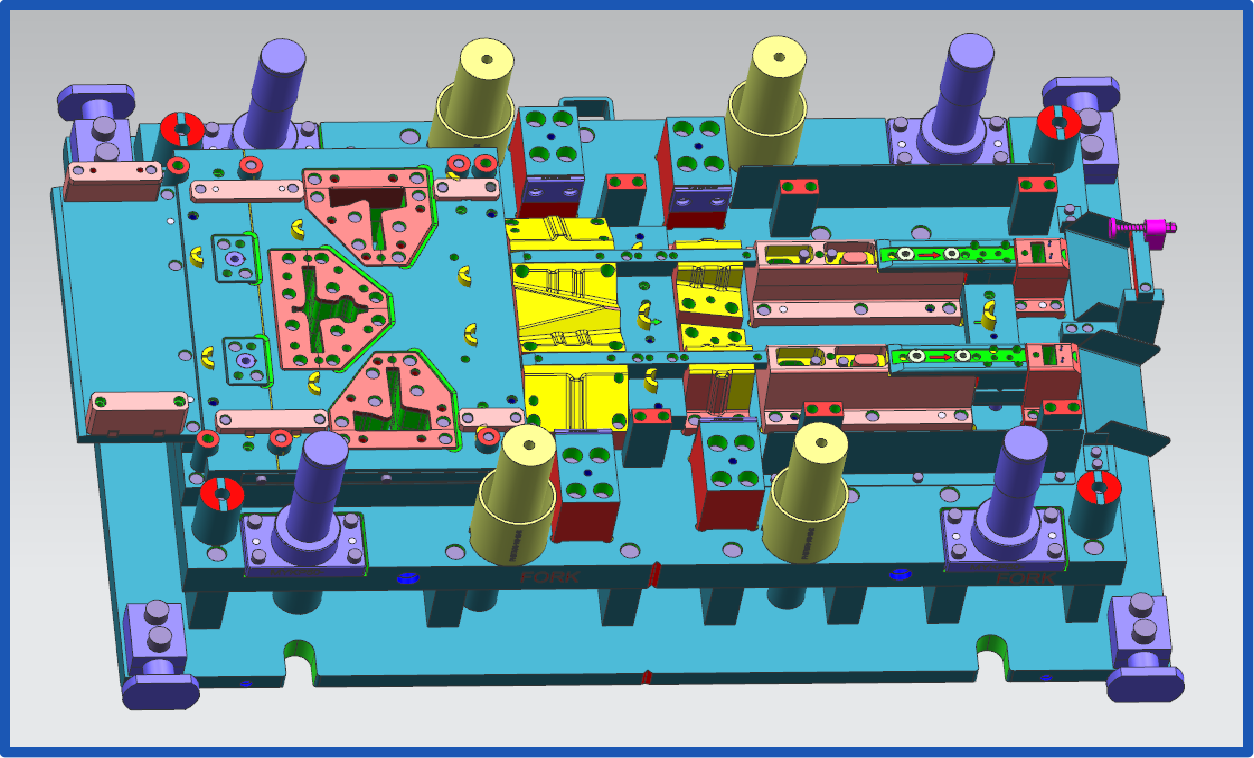
CAD Design and Detailing: Everything starts with three-dimensional modeling of every die component. Engineers create detailed models of punches, die blocks, die shoes, guide assemblies, and all auxiliary components. These models include not just the shapes, but also material specifications, surface finish requirements, and tolerance callouts. Modern CAD systems can automatically generate flat patterns, calculate blank sizes, and identify potential interference issues before any steel gets cut.
CAE Simulation and Virtual Tryout: Before committing to expensive machining operations, smart manufacturers run comprehensive simulations. According to industry research from Keysight, part and process design can significantly affect quality, with defects emerging only during first trials when corrections are both time-consuming and costly. Virtual tryouts identify these problems while changes remain inexpensive digital modifications rather than physical rework.
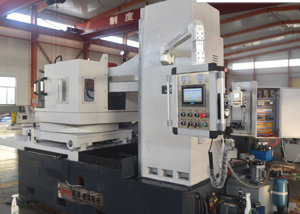
CNC Machining of Die Components: Once designs pass simulation validation, CNC machining centers cut the basic shapes. High-speed milling removes material efficiently while maintaining tight tolerances. Die blocks, punch holders, and die shoes receive their primary geometry through these operations. Modern five-axis machines can produce complex contours in single setups, reducing accumulated positioning errors.
EDM for Complex Geometries: Some features simply can't be machined conventionally. As CAM Resources explains, Electrical Discharge Machining uses electrical sparks to erode metal and create complex shapes and intricate designs that would be difficult to produce using traditional cutting methods. Wire-cut EDM excels at producing precise punch profiles and die openings with exceptional accuracy. Sinker EDM creates cavities and three-dimensional features that conventional cutters can't reach.
The press machining advantages of EDM become especially valuable when working with hardened tool steels. Since EDM doesn't physically contact the workpiece, it cuts through materials at RC 60+ hardness just as easily as softer metals—something that would rapidly destroy conventional cutting tools.
Heat Treatment: Tool steels require precise heat treatment to achieve their design hardness and toughness. This typically involves heating components to specific temperatures, holding them for calculated durations, then quenching and tempering to achieve target properties. Even small deviations from prescribed cycles can leave dies too soft (wearing prematurely) or too brittle (prone to cracking).
Grinding and Finishing: After heat treatment, precision grinding brings critical surfaces to final dimensions. Surface grinders flatten die faces to within thousandths of an inch. Profile grinders refine punch contours and die openings to exact specifications. This stage also includes polishing critical contact surfaces to reduce friction and prevent material adhesion during stamping operations.
Assembly and Prove-Out: With all components finished, technicians assemble the complete die. Guide pins and bushings get fitted with precise clearances. Punches mount into retainers, springs install, and all auxiliary systems connect. Initial tryouts verify that the machine die performs as designed, producing parts that meet all dimensional and quality requirements.
How Simulation Prevents Costly Die Failures
Imagine discovering a design flaw after investing weeks of machining time and thousands of dollars in materials. That's exactly what simulation technology prevents. Virtual die tryouts let engineers test designs against real-world conditions before any steel gets cut.
What can simulation predict? According to forming simulation research, these tools address multiple challenges simultaneously:
- Material Flow Prediction: Software models how sheet metal moves during forming operations, identifying areas where tearing or wrinkling might occur
- Springback Analysis: Advanced simulations calculate elastic recovery with remarkable accuracy, enabling precise compensation in die geometry
- Stress Distribution: Engineers can see where dies experience maximum loading, ensuring adequate strength in critical areas
- Process Optimization: Parameters like press speed, blank holder force, and lubrication can be tuned virtually rather than through expensive physical trials
The economic impact is substantial. Traditional die development might require multiple physical prototypes, each representing weeks of fabrication time. Simulation-driven development can reduce these iterations dramatically—advanced manufacturers leveraging CAE simulation for defect-free results often achieve 93% or higher first-pass approval rates. Some facilities deliver rapid prototyping in as little as five days when simulation validates designs before machining begins.
Virtual tryouts identify forming defects while changes remain inexpensive digital modifications rather than costly physical rework—transforming weeks of iteration into hours of simulation.
The technology also addresses material variation challenges. Real-world sheet metal properties vary even within the same batch, affecting part quality. Simulation software can model these variations, identifying robust process windows that accommodate normal material fluctuations without producing defects.
Quality Checkpoints Throughout Manufacturing
Building a precision die requires verification at every stage. Quality problems caught early cost little to correct; the same issues discovered during final tryout can require scrapping expensive components. Here's how thorough manufacturers maintain control throughout the process:
- Design Review: Independent verification that CAD models match part requirements, material specifications are appropriate, and all tolerances are achievable with planned processes
- Simulation Validation: Confirmation that virtual tryouts show successful forming without defects, with documented springback compensation and process parameters
- Incoming Material Inspection: Verification that tool steel grades meet chemical and hardness specifications before machining begins
- In-Process Dimensional Checks: CMM measurements of critical features at key machining stages, before operations that would make corrections impossible
- Heat Treatment Verification: Hardness testing after heat treatment to confirm components achieved target properties throughout their volume
- Final Dimensional Inspection: Comprehensive measurement of all critical features against drawing specifications before assembly
- Assembly Verification: Confirmation of proper clearances, smooth operation, and correct alignment of all components
- Sample Part Qualification: Production of test parts with complete dimensional verification against part specifications
- Capability Study: Statistical analysis of multiple sample parts to confirm the die produces consistent results within tolerance
For automotive applications, certifications like IATF 16949 mandate documented quality systems throughout die equipment manufacturing. These requirements ensure traceability from raw materials through finished tooling, with records supporting every critical decision.
The integration of advanced simulation capabilities with precision manufacturing processes has transformed what's possible in die fabrication. Manufacturers who combine CAE-driven design with rigorous quality systems deliver tooling that performs right the first time—eliminating the costly trial-and-error cycles that once defined the industry. This capability becomes especially valuable when you need to select between available options for your specific application.
How to Select the Right Press Die for Your Application
You understand die types, materials, design principles, and manufacturing processes. Now comes the decision that ties everything together: which specific tooling solution fits your project? This is where many manufacturers struggle. Commercial pages list product specifications but rarely explain how to match those specs to real-world requirements. Let's build a practical decision framework that helps you choose between standard die sets for press applications and custom-engineered solutions.
The right choice depends on multiple interrelated factors. Production volume alone doesn't determine whether you need a hydraulic press die set or a simple bench-top setup. Part complexity, material demands, tolerance requirements, and budget constraints all influence the equation. Understanding how these factors interact empowers you to make confident decisions—and avoid costly mistakes.
Matching Die Type to Production Requirements
Before evaluating specific tooling options, you need clarity on what your application actually demands. The following framework compares critical decision factors across different production scenarios:
| Decision Factor | Low Volume (Under 10,000 parts) | Medium Volume (10,000-100,000 parts) | High Volume (100,000+ parts) |
|---|---|---|---|
| Production Volume Impact | Standard die sets often sufficient; tooling cost per part less critical | Custom tooling becomes economically viable; amortization improves ROI | Custom progressive or transfer dies essential; cost-per-piece optimization paramount |
| Part Complexity Considerations | Simple geometries work with off-the-shelf solutions; complex shapes may require custom despite low volume | Moderate complexity justifies dedicated tooling; combination dies become attractive | Complex multi-station progressive dies deliver best economics for intricate parts |
| Material Type Requirements | Standard clearances work for mild steel/aluminum; exotic materials may need specialized dies | Material-specific die designs improve quality and tool life significantly | Optimized die materials and coatings essential; AHSS demands premium tooling |
| Tolerance Needs | Standard tolerances (±0.010" or looser) achievable with catalog tooling | Tighter tolerances (±0.005") favor custom-ground components | Precision tolerances (±0.002" or tighter) require fully engineered solutions |
| Budget Constraints | Minimize upfront investment; accept higher per-part costs | Balance initial tooling cost against production efficiency gains | Invest in optimized tooling; per-part savings compound over production run |
How do these factors influence your metal press selection? Consider a practical example. You need 5,000 aluminum brackets with simple 90-degree bends and ±0.015" tolerances. A standard pressing die from a catalog supplier likely handles this job efficiently. The upfront cost stays low, delivery is fast, and your per-part cost remains acceptable for this volume.
Now imagine the same bracket in stainless steel with ±0.003" tolerances and annual volumes of 250,000 units. Suddenly, standard sheet metal dies can't deliver the precision you need. The material demands specific clearances and surface treatments. A custom-engineered progressive die—though requiring significant upfront investment—dramatically reduces your cost per piece while ensuring consistent quality.
According to manufacturing specialists at Zintilon, your die selection directly impacts every aspect of your stamping operation. When you choose the right die, you'll experience improved product quality, reduced scrap rates, and enhanced production efficiency. Conversely, selecting an inappropriate die leads to dimensional variations, poor surface finishes, and increased maintenance requirements.
When Standard Dies Work vs Custom Engineering
Standard die sets for press applications offer compelling advantages: immediate availability, proven designs, and lower initial costs. But they also come with limitations that can create problems for certain applications. Understanding these boundaries helps you recognize when off-the-shelf solutions work—and when they don't.
Standard dies typically succeed when:
- Part geometry matches available tooling profiles (common hole sizes, standard bend angles)
- Material is conventional mild steel, aluminum, or copper alloys at standard gauges
- Tolerances fall within ±0.010" or looser specifications
- Production volumes remain under 25,000 parts annually
- Speed-to-market outweighs per-part cost optimization
- The press machine for metal forming has capacity matching standard tooling requirements
For metal press forming operations meeting these criteria, catalog tooling delivers excellent value. You avoid engineering costs, eliminate design lead time, and can often receive tooling within days rather than weeks.
However, certain project characteristics signal that custom engineering becomes necessary. Watch for these red flags that indicate standard solutions won't meet your needs:
- Non-standard geometries: Unusual hole shapes, complex bend sequences, or features requiring simultaneous operations in multiple directions
- Challenging materials: High-strength steels, exotic alloys, or materials with unusual springback characteristics that demand specialized compensation
- Tight tolerances: Precision requirements below ±0.005" that standard tooling cannot reliably achieve
- High-volume economics: Production quantities where tooling investment amortizes over enough parts to justify optimization
- Secondary operation elimination: Opportunities to combine multiple operations into a single die, reducing handling and improving consistency
- Quality-critical applications: Automotive, aerospace, or medical components where failure consequences drive stringent requirements
- Hydraulic press die compatibility: Large parts or deep-draw applications requiring specific tonnage ratings and die geometry
The trade-off between initial investment and long-term economics deserves careful analysis. As noted by industry experts, you should calculate the estimated costs of designing, manufacturing, and acquiring the dies—including materials, labor, and specialized equipment. Then compare these against the production rates and overall efficiency to determine true cost per part.
Consider this calculation: A custom progressive die might cost $50,000 compared to $5,000 for standard tooling. At first glance, the standard option wins easily. But if custom tooling reduces cycle time by 40% and eliminates a secondary operation, the economics shift dramatically at higher volumes. Over 500,000 parts, that $45,000 premium might save $200,000 in labor and handling costs.
The right die selection isn't about finding the cheapest option—it's about matching tooling investment to production requirements in ways that optimize total cost of ownership.
Budget constraints are real, but viewing tooling purely as an expense rather than an investment often leads to false economies. A hydraulic press die set optimized for your specific application may cost more initially yet deliver substantially lower per-part costs, better quality, and longer service life than cheaper alternatives that weren't designed for your exact requirements.
Making these decisions confidently requires accurate information about your production parameters and honest assessment of your quality requirements. But even the best-selected tooling requires ongoing attention to deliver consistent results over time. Maintenance practices and troubleshooting capabilities ultimately determine whether your die investment pays off as planned.
Die Maintenance and Troubleshooting Best Practices
You've invested significantly in precision tooling. Now what? The reality is that even the best-engineered die tools will degrade over time without proper care. Yet most commercial resources focus exclusively on product features while ignoring the maintenance practices that determine whether your tooling lasts 50,000 cycles or 500,000. Understanding lifecycle management transforms your sheet metal press die from a depreciating asset into a long-term production advantage.
Think of die maintenance like automotive care. You wouldn't drive 100,000 miles without oil changes and expect peak performance. Similarly, pressing metal through a die thousands of times creates wear patterns that, left unaddressed, cascade into quality problems and premature failure. A systematic approach to inspection, maintenance, and troubleshooting protects your investment while ensuring consistent part quality.
Preventive Maintenance Schedules That Extend Die Life
Reactive maintenance—fixing problems after they cause production disruptions—costs significantly more than prevention. According to manufacturing specialists at The Phoenix Group, a poorly defined die shop management system can dramatically decrease press line productivity and increase costs. Poor die maintenance causes quality defects during production, driving up sorting costs and increasing the likelihood of shipping defective parts.
Effective preventive maintenance follows a structured schedule based on production cycles rather than calendar time. Here's a comprehensive checklist for extending die service life:
- After Every Production Run: Clean all die surfaces to remove metal particles, lubricant residue, and debris. Inspect cutting edges for visible damage or chipping. Check guide pins and bushings for smooth operation.
- Every 10,000-25,000 Cycles: Measure critical clearances between punches and die openings. Inspect die shoe alignment using precision indicators. Check spring tension and replace any weakened components.
- Every 50,000-100,000 Cycles: Perform detailed inspection of all wear surfaces. Measure punch and die button dimensions against original specifications. Evaluate surface coatings for degradation. Consider regrinding if wear exceeds allowable limits.
- Quarterly (Regardless of Cycle Count): Review die supplies inventory to ensure replacement components are available. Inspect storage conditions for corrosion or environmental damage. Update maintenance logs and analyze wear trends.
- Annually: Complete teardown and inspection of all components. Replace worn guide components proactively. Verify die shoe flatness and parallelism. Reassess lubrication systems and update maintenance protocols based on observed wear patterns.
Environmental factors significantly affect tool life between production runs. Humidity promotes corrosion on precision steel surfaces. Temperature fluctuations cause dimensional changes that can affect clearances. Proper die storage means climate-controlled environments with protective coatings applied to all exposed steel surfaces. Setting die components on clean, level surfaces prevents distortion of die shoes over time.
Diagnosing Common Die Wear Patterns
When parts start showing quality problems, systematic diagnosis prevents wasted effort on the wrong fixes. As noted by DGMF Mold Clamps, die stamping molds in use are prone to different amounts of wear on each side position, with some parts experiencing larger scratches and faster wear rates.
Burr Formation: Excessive burrs on cut edges typically indicate worn cutting edges or incorrect clearance. If burrs appear suddenly, inspect for chipped punch tips or die button damage. Gradual burr increase suggests normal edge wear requiring sharpening. When clearance has opened beyond acceptable limits—often from repeated sharpening that shortens punches—component replacement becomes necessary rather than additional grinding.
Dimensional Drift: Parts gradually moving out of tolerance often stem from wear in forging dies or guide components. Check guide pin and bushing wear first—these components maintain alignment between upper and lower die halves. If guides measure within specification, examine the die shoe mounting surfaces for galling or wear that allows movement under press loads.
Surface Quality Degradation: Scratches, galling marks, or inconsistent finishes point to problems with die surface condition. Material buildup on punch faces requires cleaning and potentially re-polishing. Deep scratches in die cavities may indicate foreign material contamination or coating failure. For severe surface damage, professional refurbishment often proves more economical than component replacement.
Inconsistent Wear Patterns: When one side of a punch or die wears faster than the other, alignment problems exist. According to troubleshooting guides, regularly using alignment mandrels to check and adjust machine tool turret and mounting base alignment prevents this asymmetric wear pattern.
When should you regrind versus replace? The decision depends on several factors. Regrinding works well when wear is uniform and within the amount of material that can be removed while maintaining required punch length. Most punches allow 2-3mm of total shortening through successive regrinds. However, when wear is uneven, edges are chipped rather than worn, or previous regrinds have consumed available material, replacement becomes the better choice.
A data-driven approach to maintenance decisions outperforms intuition. Track cycle counts, measure wear rates, and document quality trends for each die. As industry experts emphasize, there is a need for a systematic, data-based approach to determine what dies will be worked on and when work will be done. These decisions should be based on production needs, customer satisfaction, and return on investment.
This lifecycle perspective—from initial selection through ongoing maintenance—ultimately determines the true value your tooling investment delivers. But knowing how to maintain dies is only part of the equation. Partnering with manufacturers who understand these principles from the design stage forward ensures your tooling is built for maintainability from day one.
Making Informed Decisions for Your Stamping Die Projects
You've journeyed through the complete landscape of sheet metal press die technology—from fundamental principles to advanced engineering considerations. Now it's time to pull these threads together into actionable guidance. Whether you're specifying your first tool die or optimizing an existing production line, the decisions you make about tooling partners will shape your manufacturing success for years to come.
The knowledge you've gained creates a foundation for confident decision-making. You understand how progressive, transfer, compound, and combination dies serve different production scenarios. You recognize why material selection for both dies and workpieces directly impacts tool life and part quality. You appreciate how engineering fundamentals like clearance calculations and springback compensation determine whether parts meet specifications. And you know that proper maintenance practices protect your tooling investment over time.
But knowledge alone doesn't stamp parts. Translating this understanding into production reality requires partnering with manufacturers who share your commitment to quality and can deliver on their promises.
Key Takeaways for Die Selection Success
Before engaging potential suppliers, ensure clarity on these critical factors that will drive your conversations and comparisons:
- Production Volume Alignment: Your annual quantities determine whether standard metal forming dies suffice or custom-engineered solutions deliver better economics. High-volume applications almost always justify optimized tooling investments.
- Material Compatibility: The sheet metal you're forming dictates die material requirements, clearance specifications, and surface treatment needs. Advanced high-strength steels demand premium tooling that conventional dies can't match.
- Tolerance Requirements: Precision expectations influence every aspect of die design and manufacturing. Be realistic about what tolerances you actually need versus what you've historically specified out of habit.
- Lifecycle Economics: Initial tooling cost tells only part of the story. A metal forming press running optimized dies delivers lower cost-per-piece over production runs, even when upfront investment is higher.
- Maintenance Accessibility: Tooling designed for easy maintenance and component replacement reduces long-term ownership costs. Consider how designs affect your ability to perform routine service.
These factors interact in ways that defy simple formulas. A part requiring tight tolerances in challenging materials at moderate volumes might justify custom hydraulic press tooling that wouldn't make sense for a simpler geometry at identical quantities. Context matters, and experienced partners help you navigate these trade-offs effectively.
Finding the Right Manufacturing Partner
Selecting a die supplier extends far beyond comparing quoted prices. According to industry guidance from KY Hardware, the ideal partner does more than just produce parts—they offer engineering expertise, ensure rigorous quality control, and function as an extension of your team. The cheapest quote often proves most expensive when quality problems, delivery delays, or inadequate support create downstream costs.
What should you evaluate when comparing potential metalforming presses and die suppliers?
Engineering Expertise: Can they optimize your designs for manufacturability? The best suppliers identify cost-saving opportunities and potential problems before cutting steel. Look for teams that ask probing questions about your application rather than simply quoting what you've specified. As comparative research indicates, vendors investing in advanced CAD/CAM tools, automation, and simulation capabilities gain competitive advantages through enhanced precision and reduced errors.
Quality Certifications: Credentials like IATF 16949 provide third-party validation of systematic quality processes. For automotive applications especially, this certification confirms suppliers understand and can meet rigorous Production Part Approval Process (PPAP) requirements. ISO 9001 establishes baseline quality management, while industry-specific certifications demonstrate deeper capability alignment.
Simulation Capabilities: Manufacturers leveraging CAE simulation identify potential defects before machining begins. This capability translates directly into faster development cycles and reduced iteration costs. Virtual tryouts that validate designs before physical production enable rapid prototyping timelines—some advanced facilities deliver prototypes in as little as five days.
Proven Track Record: Experience in your specific industry matters. A supplier serving automotive OEMs understands different requirements than one focused on appliance manufacturing. Ask for case studies, references, and evidence of successful projects similar to yours. First-pass approval rates above 90% indicate mature processes that get things right initially rather than through costly iteration.
The right manufacturing partner combines engineering expertise, certified quality systems, and proven production capabilities to deliver tooling that performs from day one—transforming your specifications into reliable, long-lasting metal forming dies.
Comprehensive Capabilities: Suppliers offering complete services from design through production simplify your supply chain and ensure accountability. When one partner handles CAD modeling, simulation, CNC machining, EDM processing, heat treatment, and final assembly, communication gaps disappear. This integration proves especially valuable for complex press metal forming applications where multiple specialties must coordinate seamlessly.
For readers ready to explore solutions for their stamping die projects, manufacturers combining these capabilities with demonstrated automotive expertise offer compelling partnerships. Look for suppliers whose fabrication press operations support both rapid prototyping and high-volume production, with quality systems certified to meet OEM standards. The investment in finding the right partner pays dividends through every production run your tooling supports.
Your stamping die project represents more than a tooling purchase—it's an investment in production capability that will shape your manufacturing economics for years. Armed with the knowledge from this guide, you're prepared to evaluate options critically, ask informed questions, and select partners who deliver real value beyond the quoted price. The path from raw design to flawless parts starts with these decisions.
Frequently Asked Questions About Sheet Metal Press Dies
1. What are stamping dies and how are they used in sheet metal forming?
Stamping dies are specialized precision tools that shape and cut sheet metal parts through controlled force application. They consist of a matched set of hardened steel components—primarily a punch (upper component) and die block (lower component)—mounted in a press machine. When the press applies force, the die cuts, bends, or forms flat metal sheets into predetermined three-dimensional shapes. These tools enable mass production of identical components with micron-level precision at speeds impossible with manual fabrication, making them essential for automotive, aerospace, appliance, and electronics manufacturing.
2. What is the difference between progressive dies and transfer dies?
Progressive dies and transfer dies both handle complex multi-operation stamping but work fundamentally differently. Progressive dies keep parts connected to a continuous metal strip that advances through multiple stations with each press stroke—ideal for smaller parts in extremely high volumes like electrical connectors. Transfer dies work with discrete blanks that mechanical fingers or robots move between separate stations, offering more flexibility for larger components requiring significant forming depth or complex three-dimensional shapes. Choose progressive dies for high-speed production of small parts; select transfer dies for larger, more intricate designs requiring varied orientation during forming.
3. How do I choose the right die material for my stamping application?
Die material selection depends on your sheet metal type, production volume, and tolerance requirements. For conventional mild steel or aluminum at moderate volumes, D2 tool steel (hardness RC 58-60) provides adequate wear resistance. When forming advanced high-strength steels, upgrade to powder metallurgy tool steels featuring finer carbide distribution for up to 10x better impact strength. Carbide inserts at critical contact points extend life in extreme wear situations. Surface treatments like PVD coatings (TiN, TiAlN) or ion nitriding can increase die life by 24x or more. Match your material choice to workpiece properties—harder materials require more robust tooling.
4. What causes burrs on stamped parts and how can they be prevented?
Burrs on stamped parts typically result from worn cutting edges or incorrect punch-to-die clearance. Sudden burr appearance indicates chipped punch tips or die button damage requiring immediate inspection. Gradual burr increase suggests normal edge wear needing sharpening. Prevention starts with proper clearance specification—typically 5-10% of material thickness for mild steel, increasing to 10-15% for high-strength steels. Regular maintenance including edge inspection every 10,000-25,000 cycles, proper lubrication, and timely regrinding before wear exceeds limits keeps burrs under control. When clearance opens beyond acceptable limits from repeated sharpening, component replacement becomes necessary.
5. How much does custom die tooling cost compared to standard die sets?
Custom progressive dies typically cost $25,000-$100,000+ compared to $1,000-$10,000 for standard catalog die sets. However, comparing upfront costs alone misleads. Custom tooling optimized for your specific application often reduces cycle time by 30-50%, eliminates secondary operations, and improves quality consistency. Over 500,000 parts, a $50,000 custom die delivering 40% faster cycles and eliminating one handling step could save $200,000+ in labor costs. Calculate total cost of ownership including per-part production costs, scrap rates, and quality-related expenses. For volumes under 25,000 parts with standard geometries, catalog tooling often delivers best value; higher volumes and complex parts favor custom engineering.