 Small batches, high standards. Our rapid prototyping service makes validation faster and easier —

Parts Machining Decoded: 9 Essential Points From Process To Production
What Parts Machining Really Means for Modern Manufacturing
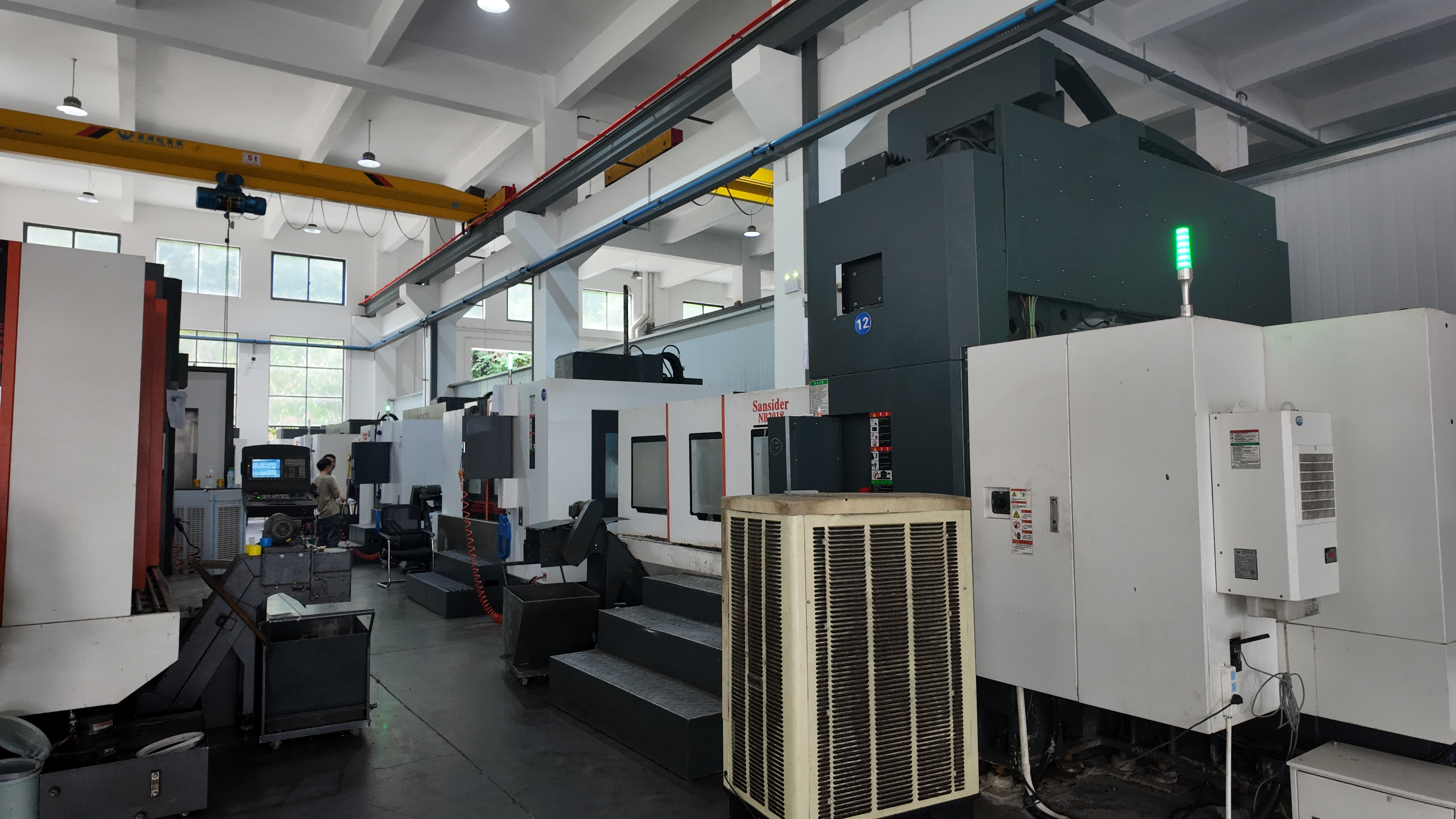
Ever wondered how the intricate metal components inside your car engine or the precision parts in aircraft landing gear come to life? The answer lies in parts machining—a subtractive manufacturing process where material is systematically removed from a solid workpiece to create exact, functional components. Think of it like a sculptor chipping away marble to reveal a masterpiece, except here, computer-controlled tools do the carving with microscopic precision.
At its core, machining transforms raw material blocks into finished machined parts through cutting, drilling, grinding, and shaping operations. This process has been refined over decades, evolving from manual lathes to today's sophisticated precision CNC machining centers that can achieve tolerances as tight as 0.025 mm.
From Raw Material to Finished Component
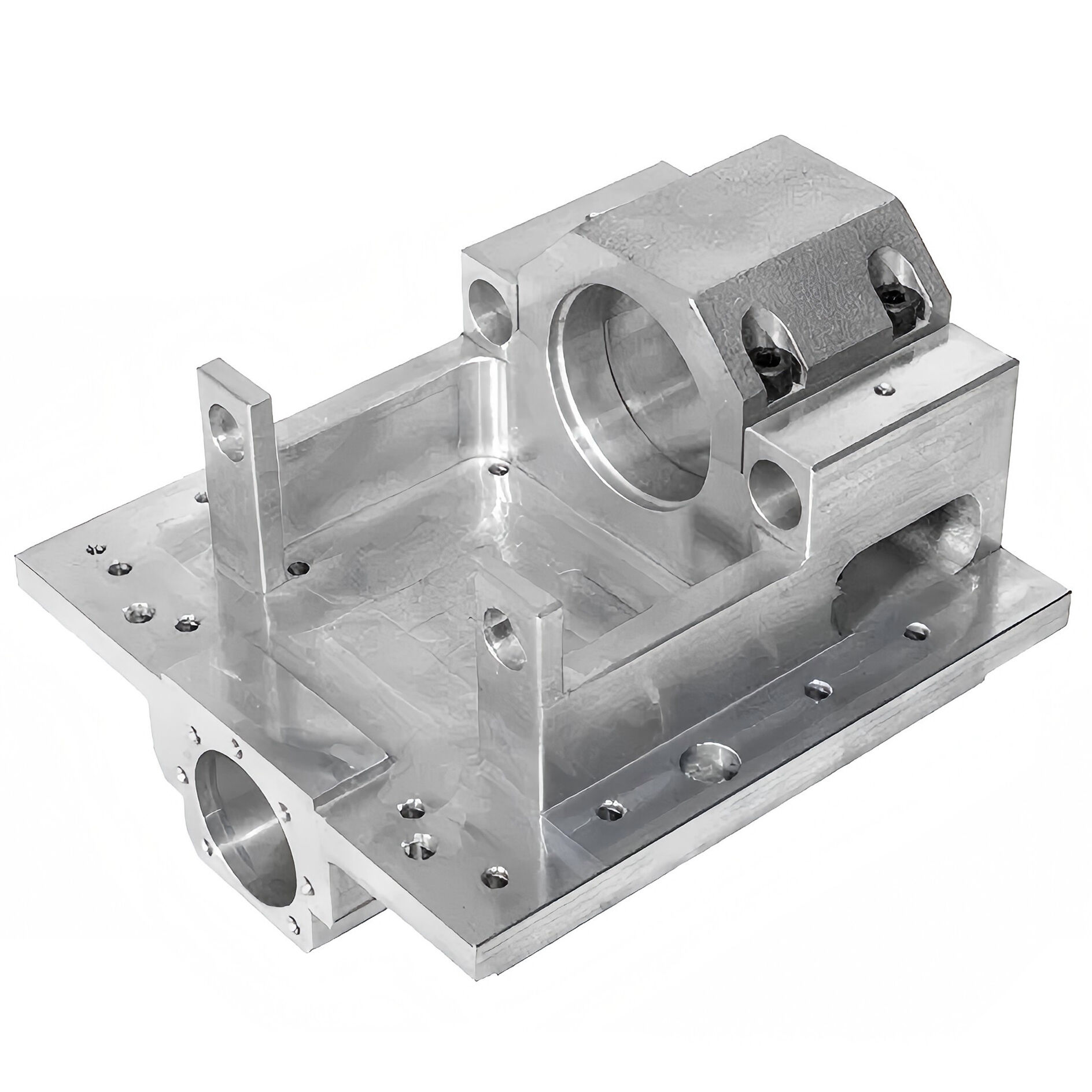
The journey begins with a workpiece—often called a blank—made from metal, plastic, or composite materials. CNC fabrication equipment then follows programmed instructions to remove excess material systematically. Each pass of the cutting tool brings the part closer to its final geometry, whether that's a simple shaft or a complex aerospace bracket with dozens of precise features.
What makes this process remarkable is its consistency. Once programmed, CNC machines run continuously, producing identical parts across large production runs with reliable, large-scale production that meets deadlines. This repeatability is something manufacturers depend on when quality cannot be compromised.
Subtractive vs Additive Manufacturing Explained
Sounds complex? Let's simplify it. Metal machining represents the subtractive approach—you start with more material than you need and remove what's unnecessary. Additive manufacturing, commonly known as 3D printing, works in reverse, building objects layer by layer from the ground up.
Here's the key distinction: subtractive processes like CNC metal cutting work with solid, uniform blocks of material, producing parts with isotropic mechanical properties. This means the finished component exhibits uniform strength regardless of which direction force is applied. Additive parts, built layer by layer, often show anisotropy—meaning strength varies depending on build orientation.
Neither method is universally superior. The choice depends entirely on your specific requirements for complexity, volume, and performance.
Why Precision Matters in Modern Manufacturing
When you're producing components for a jet engine or a surgical instrument, "close enough" simply doesn't exist. Precision CNC machining delivers the dimensional accuracy these applications demand—something that remains unmatched by newer technologies.
From automotive transmissions to aerospace structural components, machining remains the foundation of industries where component failure is never an option. Its ability to work with virtually any material while maintaining exceptional tolerances makes it indispensable for production-grade manufacturing.
Consider the numbers: modern CNC machines achieve tolerances of ±0.025 mm, while even advanced 3D printing systems typically operate around ±0.1 mm. For mission-critical components in aerospace, medical devices, and automotive systems, this four-fold difference in precision isn't just important—it's essential.
Beyond precision, machining offers unparalleled material versatility. Whether you're working with aluminum alloys, hardened steel, titanium, or engineering plastics, subtractive methods handle them all. This flexibility, combined with proven reliability developed over decades of industrial refinement, explains why the global CNC machine market exceeded $70 billion in 2023—cementing its role as the backbone of modern production.
Core Machining Processes and When to Use Each
Now that you understand what parts machining accomplishes, let's explore how it actually happens. Not all machining operations are created equal—each process has distinct strengths that make it ideal for specific applications. Choosing the right method can mean the difference between a cost-effective production run and an expensive lesson in manufacturing.
Think of these processes as specialized tools in a craftsman's workshop. You wouldn't use a sledgehammer to drive a finishing nail, and similarly, you wouldn't choose CNC turning when swiss machining delivers the micro-precision your application demands. Let's break down each core process so you can match the right technique to your project requirements.
CNC Turning for Cylindrical Components
Imagine holding a piece of wood against a spinning pottery wheel—that's essentially how CNC turning works, except with metal and computerized precision. In this process, the workpiece rotates rapidly while a stationary cutting tool removes material, creating cylindrical or conical shapes with exceptional accuracy.
The key components of a CNC lathe include the chuck (which holds and rotates the workpiece), the tool holder (positioning cutting tools precisely), and the carriage (moving along the lathe bed to control cutting depth). This configuration excels at producing:
- Shafts and axles with precise diameters
- Threaded components like bolts and screws
- Pulleys, bushings, and sleeves
- Any part with rotational symmetry
When you need a reliable cnc turning service for high-volume production of rotationally symmetric parts, this process delivers speed and consistency. Operations like facing, threading, grooving, and boring can all be performed in a single setup, reducing handling time and improving accuracy.
However, CNC turning has limitations. It's best suited for external cuts on cylindrical parts—intricate internal features or non-symmetric geometries typically require additional processes or different methods entirely.
Multi-Axis Milling Capabilities
While turning rotates the workpiece, CNC milling takes the opposite approach—the cutting tool rotates while the workpiece remains stationary (or moves along controlled axes). This fundamental difference opens up possibilities for complex three-dimensional shapes that turning simply cannot achieve.
Standard 3-axis milling moves along X, Y, and Z coordinates, but the real magic happens with multi-axis configurations. 5 axis cnc machining services incorporate two additional rotational axes, allowing the cutting tool to approach the workpiece from virtually any angle. This capability is transformative for complex geometries.
Consider what multi-axis milling enables:
- Turbine blades with compound curves machined in a single setup
- Engine blocks with features on multiple faces
- Medical implants with organic, flowing contours
- Molds and dies with intricate cavity details
CNC milled parts benefit from the process's versatility across materials—aluminum, steel, titanium, plastics, and composites all respond well to milling operations. For aerospace components, automotive prototypes, and medical devices requiring complex shapes, milling is often the go-to solution.
The tradeoff? Multi-axis equipment carries higher costs, and programming complexity increases with each additional axis. For simpler geometries, basic 3-axis milling or turning may be more economical.
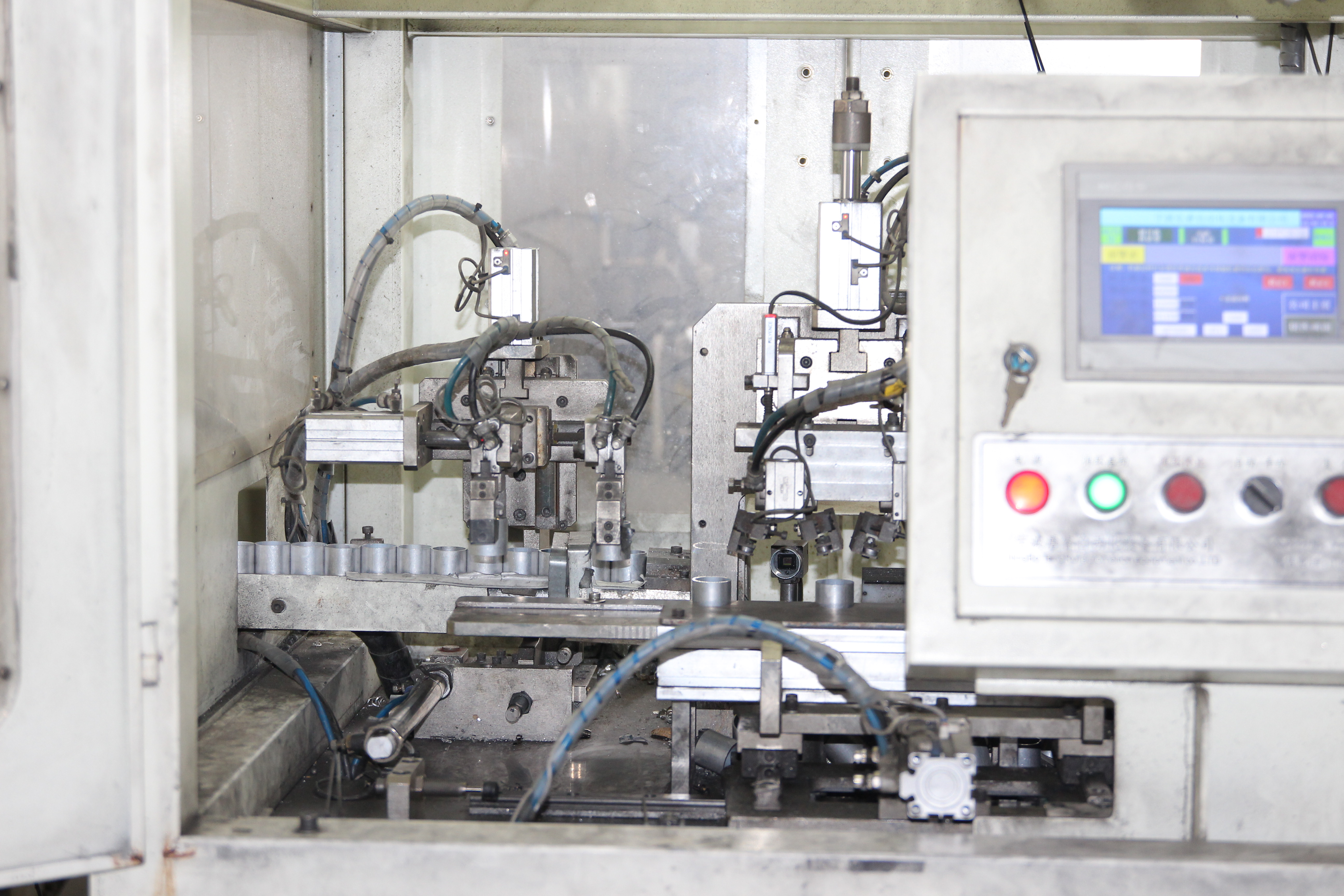
Swiss Machining for Micro-Precision Parts
When tolerances measured in thousandths of an inch aren't tight enough, swiss machining steps in. Originally developed in the 1800s to manufacture Swiss watch components, this specialized turning process has evolved into the gold standard for small, complex, high-precision parts.
What makes Swiss CNC machines different? The secret lies in the guide bushing—a component that supports the workpiece extremely close to the cutting tool. This minimizes deflection and vibration, enabling tolerances as tight as ±0.0002 inches. Traditional lathes simply cannot match this stability on slender or delicate components.
Swiss machining shines in applications requiring:
- Medical devices—surgical tools, implants, diagnostic components
- Aerospace fasteners, control pins, and precision connectors
- Electronics terminals, pins, and micro components
- Hydraulic spools, valves, and custom fittings
Modern CNC Swiss machines combine turning with live tooling capabilities, enabling milling, drilling, and tapping operations in a single cycle. This eliminates secondary operations and reduces handling—critical advantages for high-volume production of intricate parts.
Specialized Processes: Drilling, Grinding, and EDM
Beyond the primary methods, several specialized processes address specific manufacturing challenges:
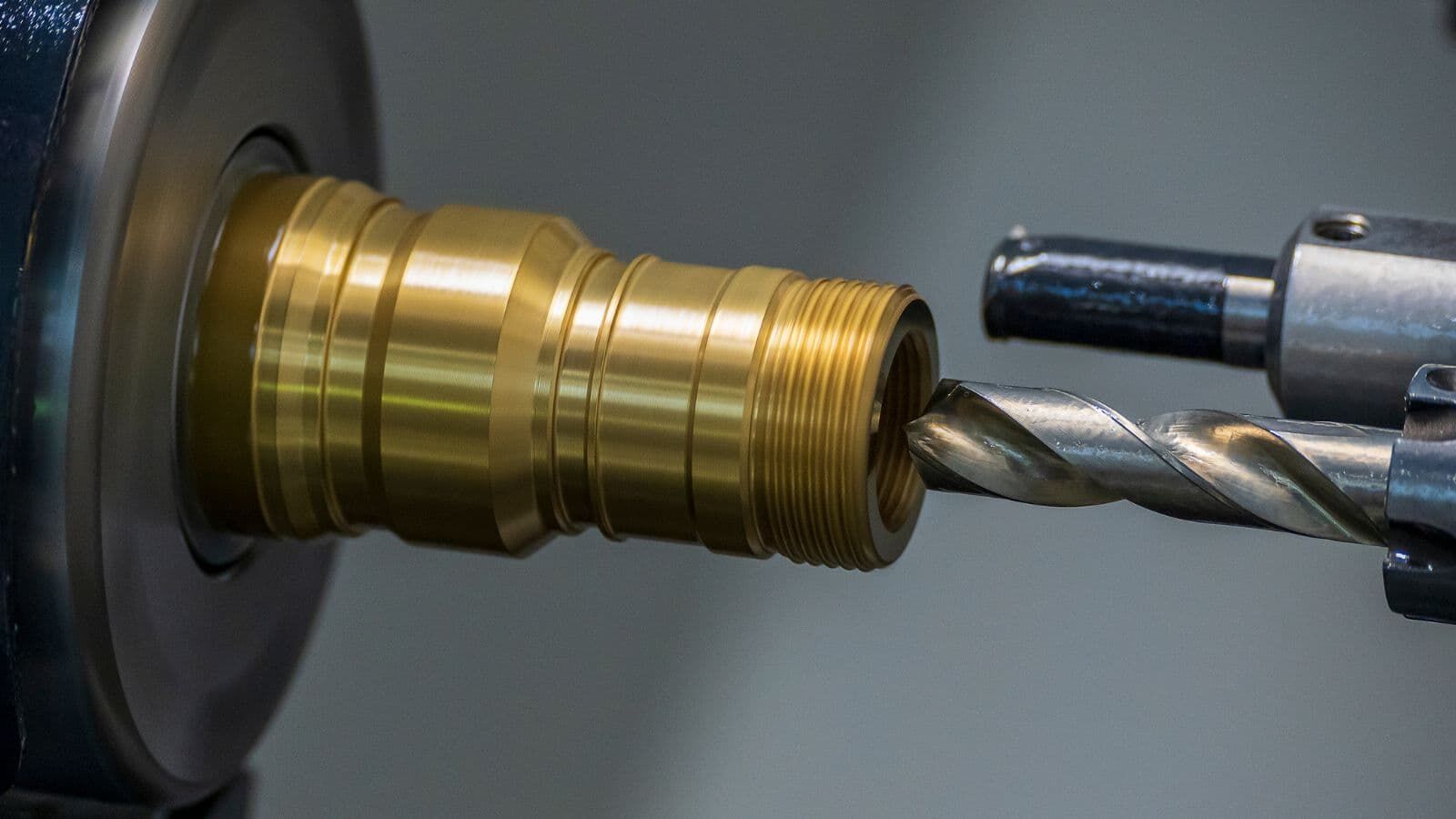
Drilling creates holes of various diameters and depths. While seemingly straightforward, precision drilling requires careful control of feed rates, speeds, and tool selection to prevent wandering or surface damage. Deep-hole drilling for hydraulic components demands specialized equipment and techniques.
Grinding uses abrasive wheels to achieve exceptionally smooth surface finishes and tight tolerances. When cnc cutting leaves parts requiring final precision refinement, grinding delivers surface finishes superior to other methods. It's essential for hardened materials that would quickly destroy conventional cutting tools.
Electrical Discharge Machining (EDM) takes a completely different approach. Rather than mechanical cutting, EDM uses controlled electrical sparks to erode material from conductive workpieces. This non-contact process excels at:
- Machining hardened tool steels, titanium, and carbide
- Creating sharp internal corners impossible with rotating tools
- Producing intricate mold cavities and die details
- Drilling small, deep holes in aerospace components
EDM achieves surface finishes as fine as Ra 0.1 μm, though material removal rates are significantly slower than mechanical methods. For hard materials or delicate details where precision trumps speed, EDM remains invaluable.
Process Selection Guide
Choosing the right process depends on multiple factors working together. The following comparison helps clarify when each method delivers optimal results:
| Process Name | Best For (Part Types) | Typical Tolerances | Material Compatibility | Production Volume Suitability |
|---|---|---|---|---|
| CNC Turning | Cylindrical parts, shafts, threaded components | ±0.025 mm to ±0.05 mm | Metals, plastics (rotational symmetry required) | Medium to high volume |
| CNC Milling (3-axis) | Flat surfaces, pockets, slots, simple 3D shapes | ±0.025 mm to ±0.05 mm | Metals, plastics, composites | Low to medium volume |
| 5-Axis Milling | Complex geometries, turbine blades, molds | ±0.01 mm to ±0.025 mm | Metals, plastics, composites | Low to medium volume |
| Swiss Machining | Small, intricate, high-precision parts | ±0.005 mm (±0.0002") | Metals, engineering plastics (PEEK, Delrin) | Medium to high volume |
| Drilling | Holes of various depths and diameters | ±0.05 mm to ±0.1 mm | All machinable materials | All volumes |
| Grinding | Final finishing, hardened materials | ±0.005 mm to ±0.01 mm | Hardened metals, ceramics | Low to medium volume |
| EDM | Hard materials, intricate details, sharp corners | ±0.005 mm to ±0.01 mm | Conductive materials only | Low volume, specialized applications |
Many manufacturers offering comprehensive cnc turning services also provide milling, grinding, and specialized capabilities. This integrated approach allows engineers to select optimal processes—or combine them—based on part geometry, material requirements, and production economics rather than equipment availability.
Understanding these process fundamentals positions you to make informed decisions. But selecting the right machining method is only part of the equation—choosing the right material is equally critical to project success.
Material Selection Guide for Machined Components
You've identified the right machining process—now comes an equally important decision: which material should your part be made from? Material selection directly impacts machinability, part performance, cost, and lead time. Choose wisely, and your components perform flawlessly for years. Choose poorly, and you're facing premature failures, excessive tool wear, or budget overruns.
The good news? Understanding a few fundamental principles makes this decision far less daunting. Let's walk through the primary material categories and their sweet spots in manufacturing applications.
Metals from Aluminum to Titanium
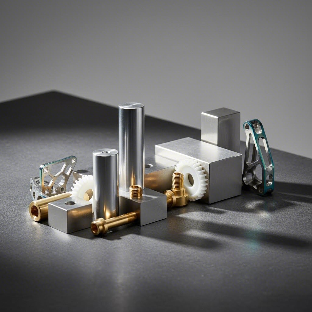
Metals remain the workhorses of parts machining, offering combinations of strength, durability, and machinability that other materials simply cannot match. However, not all metals behave the same under cutting tools.
Aluminum tops the machinability charts. Its softness allows for fast cutting speeds, extended tool life, and excellent surface finishes. Aerospace, automotive, and consumer electronics industries rely heavily on aluminum alloys like 6061 and 7075 for structural components where weight savings matter.
Steel and stainless steel offer superior strength but demand more from cutting tools. Low-carbon steels machine relatively easily, while hardened tool steels require specialized approaches. Stainless steel grades like 303 (free-machining) cut cleaner than 316 (corrosion-resistant but gummier), so grade selection significantly impacts production efficiency.
Titanium presents the greatest challenge—and reward. Its exceptional strength-to-weight ratio makes it indispensable for aerospace and medical implants, but poor thermal conductivity causes heat to concentrate at the cutting edge, accelerating tool wear. Machining titanium successfully requires slower speeds, rigid setups, and premium tooling.
For applications requiring excellent bearing surfaces and corrosion resistance, machining bronze delivers outstanding results. Bronze alloys machine smoothly, producing parts with natural lubricity ideal for bushings, bearings, and marine hardware.
- Aluminum: Excellent machinability, lightweight, corrosion-resistant—ideal for aerospace brackets, housings, heat sinks
- Mild Steel: Good machinability, affordable, strong—suited for structural components, fixtures, machinery parts
- Stainless Steel: Moderate machinability, corrosion-resistant—best for medical devices, food processing, marine applications
- Brass: Excellent machinability, decorative finish—used for fittings, valves, electrical connectors
- Bronze: Good machinability, self-lubricating—perfect for bearings, bushings, gears
- Titanium: Difficult to machine, exceptional strength-to-weight—essential for aerospace, medical implants, racing components
Engineering Plastics and Their Advantages
When weight reduction, electrical insulation, or chemical resistance takes priority, engineering plastics offer compelling alternatives to metals. These materials machine cleanly and often eliminate secondary finishing operations.
So what is delrin, and why does it appear so frequently in machining conversations? Delrin plastic is DuPont's tradename for acetal homopolymer—a semi-crystalline thermoplastic with exceptional dimensional stability, low friction, and high tensile strength (approximately 74.8 MPa). The delrin material excels in applications requiring precision gears, bearings, and sliding components that must operate without lubrication.
But what is acetal exactly? Acetal (polyoxymethylene or POM) is the broader material family that includes both homopolymers like Delrin and copolymers sold under names like Celcon and Hostaform. While polyacetal delrin offers superior mechanical strength (yield strength of 11,000 psi versus 9,500 psi for copolymers), acetal copolymers provide better chemical resistance and lack the porosity issues that can affect homopolymers in food or medical applications.
Nylon for machining applications delivers high impact resistance and excellent wear properties. With tensile strength around 71.9 MPa, nylon handles repeated stress cycles well, making it suitable for gears, rollers, and structural components where toughness matters.
- Delrin/Acetal: Low friction, high rigidity, self-lubricating—gears, bearings, bushings, precision components
- Nylon: High impact resistance, good wear properties—gears, rollers, structural parts, wear pads
- Polycarbonate: Transparent, impact-resistant (66.2 MPa tensile strength)—lenses, guards, housings, medical devices
- PTFE (Teflon): Extreme chemical resistance, low friction, wide temperature range (-250°C to +250°C)—seals, gaskets, chemical handling components
- PEEK: High-temperature performance, excellent mechanical strength—aerospace, medical implants, semiconductor equipment
Matching Materials to Application Requirements
Selecting the optimal material means balancing multiple factors simultaneously. Consider these key decision drivers:
Mechanical requirements: What loads will the part experience? Titanium and hardened steels handle extreme stress, while aluminum and plastics suit lighter-duty applications. For parts requiring both strength and sliding contact, bronze or delrin often outperform alternatives.
Environmental exposure: Will your component face corrosive chemicals, moisture, or extreme temperatures? Stainless steel and PTFE resist harsh chemicals, while acetal copolymers handle hot water exposure better than Delrin (which should avoid prolonged immersion above 60°C).
Machinability and cost: Materials that cut easily reduce machining time and tooling costs. Aluminum, brass, and free-machining plastics produce parts faster than titanium or hardened steel. When budgets are tight, optimizing material selection often delivers more savings than negotiating machining rates.
Industry compliance: Medical devices may require FDA-approved plastics or implant-grade titanium. Food processing demands materials meeting sanitary standards. Aerospace applications often specify certified alloys with full traceability.
The relationship between material choice and machining success runs deep. A material that's perfect for your application but nightmarish to machine will drive up costs and extend lead times. Conversely, an easily machined material that fails in service creates far more expensive problems.
With materials and processes now covered, understanding how tight your tolerances actually need to be—and what that precision costs—becomes your next critical consideration.
Tolerances and Surface Finishes Explained
You've selected your machining process and material—but how precise does your part actually need to be? This question sits at the heart of every successful manufacturing project. Specify tolerances too loose, and your components won't fit or function properly. Specify them too tight, and you'll pay premium prices for precision you don't actually need.
Understanding tolerances and surface finishes empowers you to communicate exactly what your application requires—no more, no less. Let's decode these specifications so you can make informed decisions that balance performance with cost efficiency.
Understanding Tolerance Specifications
Every manufacturing process involves some degree of variation—it's simply unavoidable. Tolerances define the acceptable range of this variation for specific dimensions or features on your part. Think of tolerance as a permission slip: you're telling the machinist exactly how much deviation from the nominal dimension is acceptable.
When you specify a shaft diameter of 25.00 mm with a tolerance of ±0.05 mm, you're stating that any finished part measuring between 24.95 mm and 25.05 mm meets your requirements. Parts outside this range get rejected—simple as that.
Tolerances typically fall into two categories:
- Standard tolerances: General-purpose specifications that most CNC machining parts achieve without special procedures. These typically range from ±0.05 mm to ±0.1 mm depending on the process and feature size.
- Tight tolerances: More demanding specifications requiring slower cutting speeds, additional inspection, and often specialized equipment. Moving into the ±0.01 mm to ±0.025 mm range significantly increases manufacturing complexity.
Beyond simple dimensional tolerances, Geometric Dimensioning and Tolerancing (GD&T) provides a symbolic language for defining more complex requirements. GD&T addresses the relationships between features—their form, orientation, location, and profile—ensuring parts assemble and function correctly even with manufacturing variations.
Surface Finish Standards and Applications
While tolerances control dimensions, surface finishes govern the texture of your machined parts. Surface roughness—those fine patterns etched into a material's exterior from the machining process—significantly impacts performance, longevity, and aesthetics of precision machining parts.
The most common measurement is Ra (roughness average), which quantifies the average deviation of the surface profile from the mean line. Lower Ra values indicate smoother surfaces. Here's what different ranges typically mean:
- Ra 0.4-0.8 μm: Standard machined finish—suitable for most mechanical components
- Ra 0.1-0.4 μm: Fine finish—required for sealing surfaces and precision bearings
- Ra 0.025-0.1 μm: Mirror finish—needed for optical components and specialized applications
Why does surface finish matter so much? Consider these performance factors:
- Friction and wear: Smoother surfaces reduce resistance and extend component life in sliding applications
- Fatigue strength: Surface imperfections act as stress concentrators, reducing a part's ability to withstand repeated loading cycles
- Sealing performance: O-rings and gaskets require specific surface finishes to prevent leaks
- Corrosion resistance: Rough surfaces provide more area for corrosive agents to attack
Balancing Precision with Cost Efficiency
Here's where manufacturing economics meets engineering judgment. The relationship between tighter tolerances and cost isn't linear—it escalates faster than most expect. Research indicates that moving from ±0.05 mm to ±0.02 mm may raise costs by around 50%, but going further from ±0.02 mm to ±0.01 mm can multiply costs several times.
Why does this happen with each cnc machining part requiring tighter specs?
- Slower cutting speeds reduce material removal rates
- More frequent inspection requires additional time and equipment
- Higher scrap rates increase material waste
- Specialized tooling and fixtures add setup costs
- Thermal management becomes more critical
The most expensive tolerance is often the one that doesn't add functional benefit. Many design drawings include "safety tolerances"—very tight values included out of caution rather than based on actual function. One European automotive supplier discovered that relaxing non-critical tolerances from ±0.01 mm to ±0.03 mm reduced machining costs by approximately 22%.
Before finalizing specifications, ask yourself: "Do we need ±0.01 mm, or are we just assuming we do?" Focus tight tolerances only on features that truly require them—mating surfaces, critical interfaces, and functional dimensions where precision directly affects performance.
| Machining Process | Standard Tolerance Range | Achievable Tight Tolerance | Typical Applications |
|---|---|---|---|
| CNC Milling | ±0.05 mm to ±0.1 mm | ±0.01 mm to ±0.025 mm | Housings, brackets, structural components |
| CNC Turning | ±0.025 mm to ±0.05 mm | ±0.01 mm to ±0.02 mm | Shafts, pins, threaded components |
| Swiss Machining | ±0.01 mm to ±0.025 mm | ±0.005 mm (±0.0002") | Medical devices, micro components |
| Grinding | ±0.01 mm to ±0.025 mm | ±0.002 mm to ±0.005 mm | Bearing surfaces, hardened parts |
| EDM | ±0.01 mm to ±0.025 mm | ±0.005 mm to ±0.01 mm | Mold cavities, intricate details |
Precision machining services deliver remarkable accuracy when you need it—but smart engineering means specifying that precision only where it genuinely adds value. By understanding the tolerance cost curve and applying tight specifications judiciously, you'll produce functional parts without overspending on unnecessary precision.
With tolerances and surface finishes now demystified, understanding how your design translates into actual machine movements through CNC programming becomes the next piece of the manufacturing puzzle.
CNC Programming and CAM Software Fundamentals
So you've got your process selected, material chosen, and tolerances defined—but how does your digital design actually become physical instructions that a CNC machine can follow? This is where programming enters the picture, transforming your CAD model into precise movements that cutting tools execute with remarkable accuracy.
For those new to parts machining, CNC programming might seem like an intimidating black box. The good news? You don't need to become a coding expert to understand how it works. Let's pull back the curtain on the workflow that turns your ideas into finished cnc machine parts.
The CAD to CAM Workflow
Imagine you've designed a complex bracket in your CAD software. That 3D model contains all the geometric information—dimensions, curves, holes, and features—but the CNC machine can't read it directly. This is where CAM (Computer-Aided Manufacturing) software becomes essential.
CAM acts as the translator between your design intent and machine reality. It analyzes your CAD geometry and generates toolpaths—the precise routes cutting tools will follow as they shape raw material into your finished component. Modern CAM packages like Autodesk Fusion 360 or SolidCAM enable machinists to design, simulate, and test these toolpaths before any metal gets cut.
Here's the step-by-step journey from concept to completed part:
- Create or import the CAD model: Start with a 3D design in formats like STEP, IGES, or native CAD files. Ensure the model accurately represents your finished part geometry.
- Define the stock material: Tell the CAM software what size and shape raw material you're starting with—this determines how much material needs removal.
- Select machining operations: Choose appropriate strategies for each feature—roughing to remove bulk material, finishing for final surfaces, drilling for holes, and so on.
- Generate toolpaths: The CAM software calculates optimal cutting routes based on your selected operations, tool geometries, and machining parameters.
- Simulate the program: Run virtual machining to verify toolpaths, detect potential collisions, and confirm the finished result matches your design intent.
- Post-process to G-code: Convert the toolpath data into machine-specific instructions your CNC controller can execute.
- Transfer and run: Load the program onto your machine and produce the physical part.
This workflow applies whether you're performing cnc machining milling operations on a 3-axis mill or executing complex 5-axis contouring. The fundamental process remains consistent—only the complexity of toolpath strategies and programming parameters changes.
G-Code Basics for Beginners
At the heart of every CNC operation lies G-code—the fundamental language that controls CNC machines. Think of G-code as a set of simple instructions telling the machine exactly where to move, how fast to travel, and what operations to perform.
Each line of a G-code program contains commands that the machine executes sequentially. For example:
- G00: Rapid positioning—move quickly through air to the next location
- G01: Linear interpolation—move in a straight line while cutting
- G02/G03: Circular interpolation—cut along arcs (clockwise or counter-clockwise)
- M03: Start the spindle rotating
- M05: Stop the spindle
A simple coordinate like "X1 Y2 Z3" tells the machine to position the tool at those specific locations along each axis. When combined with movement commands and feed rate specifications, these coordinates create the complete cnc cut sequence.
Here's what makes G-code programming valuable to understand: according to a CNCCookbook survey, the overwhelming majority of CNC professionals read, write, or tweak G-code programs regularly. Even if CAM software generates most of your code, knowing how to interpret and modify it provides significant advantages in troubleshooting and optimization.
The financial incentive is real too—CNC Programmers earn an average salary of $54,000/year, compared to $42,000/year for general CNC operators. That proficiency commands higher value in the marketplace.
How Toolpaths Determine Part Quality
If G-code is the language, toolpaths are the sentences that tell the complete story of how your part gets made. A toolpath in CNC machining is the exact route that a cutting tool takes while working through material—defining every twist, turn, and depth level.
Toolpath design directly impacts three critical outcomes:
- Surface finish quality: How the tool engages material determines the texture left behind. Improper stepover distances or feed rates create visible tool marks.
- Tool life: Aggressive toolpaths that overload cutting edges accelerate wear. Well-designed paths maintain consistent chip loads, extending tool longevity.
- Machining efficiency: Optimized toolpaths minimize air cutting (tool moving without removing material) and reduce cycle times.
Different toolpath strategies serve different purposes. Roughing toolpaths prioritize material removal speed, using techniques like adaptive clearing that maintain constant tool engagement to optimize chip load. Finishing toolpaths prioritize surface quality, using finer stepovers and slower feeds to achieve smooth results.
Text milling operations for engraving require specialized toolpaths that trace letter outlines precisely. Thread milling uses helical interpolation to create internal and external threads. Each application demands toolpath strategies tailored to its specific requirements.
The simulation step in CAM programming proves invaluable here. By virtually testing toolpaths before physical machining, you can identify potential collisions, verify material removal, and catch programming errors—all without risking expensive materials or machine damage. Modern CAM software makes this verification accessible even to newcomers, though expertise still matters for optimizing results.
One particularly powerful advancement in recent CAM releases involves cutter compensation capabilities. RhinoCAM 2025, for instance, allows operators to insert compensation adjustments directly into output toolpaths. This means machinists can correct for tool wear or minor inaccuracies on the CNC controller itself—reducing setup times and providing a safety net for high-precision work.
Understanding these programming fundamentals positions you to communicate effectively with machinists and make informed decisions about manufacturing approaches. But programming represents just one factor in choosing how to produce your parts—comparing CNC machining against alternative manufacturing methods reveals when each approach delivers optimal results.
Choosing Between Machining and Alternative Methods
With your CNC programming knowledge now in place, a bigger question emerges: is machining even the right approach for your project? The manufacturing landscape offers multiple pathways to finished parts—3D printing, casting, forging, and injection molding each bring unique strengths to the table. Choosing wisely can save thousands of dollars and weeks of lead time. Choosing poorly? That's an expensive lesson nobody wants.
Here's the reality: no single manufacturing method dominates every application. The smartest engineers evaluate each project individually, matching production requirements to the method that delivers optimal results. Let's build a decision framework you can apply to any manufacturing challenge.
CNC Machining vs 3D Printing Decision Criteria
This comparison generates more debate than almost any other in modern manufacturing. Both cnc prototyping and additive manufacturing produce functional parts—but they excel in fundamentally different scenarios.
Geometric complexity: 3D printing creates complex internal structures, lattice designs, and organic shapes that would be difficult or impossible to achieve with CNC machining. Sealed cavities, curved internal channels, and consolidated assemblies favor additive approaches. However, if your geometry involves primarily external features with standard radii and accessible surfaces, machining delivers superior results.
Material properties: CNC machining works with solid, homogeneous material blocks—meaning finished parts exhibit stronger and more durable mechanical properties. The layer-by-layer nature of 3D printing can introduce anisotropy and porosity that affects performance under stress. For production-grade components requiring high strength and reliability, machining typically wins.
Precision requirements: When tolerances matter, machining holds a clear advantage. CNC prototype machining routinely achieves ±0.025 mm, while most 3D printing technologies operate around ±0.1 mm. For mating surfaces, precision fits, and critical dimensions, subtractive methods deliver consistency additive processes struggle to match.
Time-to-first-part: Here's where rapid cnc prototyping and 3D printing both shine—but for different reasons. 3D printing requires no tooling and can produce complex prototypes directly from CAD files within hours. CNC machining may need fixture setup but offers faster material removal rates for simpler geometries. For initial concept validation where exact material properties don't matter, 3D printing often gets parts in hand faster.
When Casting or Forging Makes More Sense
Beyond the machining-versus-printing debate, traditional forming processes deserve serious consideration—especially as production volumes increase.
Casting advantages: When your design includes complex internal cavities, irregular shapes, or non-uniform wall thicknesses, casting can create these features in a single pour. Once mold tooling is developed, the process becomes highly scalable—producing thousands of identical parts with consistent form. Die casting achieves tolerances around ±0.1 mm per 25 mm of dimension, acceptable for many applications.
Casting excels for engine blocks, turbine housings, and structural components where near-net-shape production minimizes material waste. The catch? Upfront mold creation requires significant investment and lead time. If your design isn't finalized, that tooling cost becomes a liability.
Forging strengths: When maximum strength matters—think aerospace structural components or high-stress automotive parts—forging delivers superior mechanical properties. The process aligns metal grain structure along load paths, creating parts with exceptional fatigue resistance. However, forging typically produces near-net shapes requiring finish machining, and tooling costs limit its viability for low volumes.
Injection molding: For plastic parts in high volumes, injection molding achieves per-part costs that machining simply cannot match. Once tooling is amortized across thousands or millions of units, the economics become compelling. But prototype machining remains preferable during development phases when design changes are still expected.
Carbon fiber prototyping represents a specialized case where material properties drive method selection. Carbon fiber composites often require layup and curing processes rather than traditional machining, though CNC trimming and drilling of cured parts is common.
Volume Thresholds and Cost Crossover Points
The economic sweet spot for each manufacturing method depends heavily on quantity. Understanding these crossover points prevents costly mistakes.
Low volume (1-50 parts): CNC machining and 3D printing dominate this range. No tooling investment means you pay primarily for machine time and material. Prototype machining delivers production-quality parts from the start, while 3D printing enables rapid iteration on complex geometries.
Medium volume (50-500 parts): Casting starts becoming competitive around the 40-100 unit mark, depending on part complexity and mold costs. Die casting and investment casting offer better per-part economics as volumes increase, though setup times remain longer than machining.
High volume (500+ parts): Traditional forming processes—casting, forging, injection molding—deliver significant cost advantages. The initial tooling investment spreads across many units, dramatically reducing per-part costs. A part costing $20.00 at 100 units can drop to $2.00 at 5,000 units due to volume economies.
Beyond pure economics, consider these practical factors:
- Design stability: Frequent changes favor machining's flexibility; locked designs benefit from tooling investments
- Material requirements: Exotic alloys like titanium may machine more reliably than they cast—titanium DMLS/CNC hybrid approaches sometimes offer the best balance
- Lead time pressure: Urgent projects favor processes without tooling requirements
- Surface finish needs: Machining delivers superior finishes; casting often requires secondary operations
Manufacturing Method Comparison
| Factor | CNC Machining | 3D Printing | Casting | Injection Molding |
|---|---|---|---|---|
| Best Volume Range | 1-500 parts | 1-100 parts | 100-10,000+ parts | 1,000-1,000,000+ parts |
| Typical Tolerances | ±0.025 mm | ±0.1-0.3 mm | ±0.1-0.5 mm | ±0.05-0.1 mm |
| Material Strength | Excellent (isotropic) | Good (anisotropic) | Good to excellent | Good (plastics only) |
| Geometric Complexity | Moderate to high | Very high | High (internal features) | High (with tooling) |
| Time-to-First-Part | 1-5 days | Hours to 2 days | 2-8 weeks | 4-12 weeks |
| Tooling Required | Minimal (fixtures) | None | Molds/patterns | Injection molds |
| Material Options | Metals, plastics, composites | Plastics, some metals | Metals primarily | Plastics only |
| Cost Trend with Volume | Relatively flat | Flat | Decreases sharply | Decreases sharply |
The smartest manufacturing decisions often combine methods strategically. Many manufacturers use a hybrid approach—casting parts to near-net shape, then machining critical features for improved tolerances. This captures casting's efficiency for bulk geometry while achieving machining's precision where it matters most.
Ultimately, the "best" manufacturing method is the one that meets your specific requirements for quality, timeline, and budget. A cnc prototype that validates your design quickly may be worth more than a perfectly optimized production process that arrives too late. Evaluate each project on its own terms, and let the application requirements—not manufacturing preferences—drive your decision.
With manufacturing method selection now clarified, understanding what drives costs in parts machining helps you budget accurately and identify opportunities for savings.
Understanding Parts Machining Costs and Pricing
Ever received a quote for machined parts and wondered why a seemingly simple component costs hundreds of dollars? You're not alone. Pricing in parts machining often feels like a black box—but it doesn't have to be. Understanding what drives costs empowers you to make smarter design decisions, communicate effectively with suppliers, and ultimately get better value for your manufacturing budget.
The truth is, cnc machining price depends on multiple interconnected factors. Some you control directly through design choices. Others depend on production volume, supplier capabilities, or market conditions. Let's pull back the curtain on machining economics so you can approach your next project with confidence.
Primary Cost Drivers in Parts Machining
What actually determines the price tag on your machined components? While every project differs, certain factors consistently dominate the final bill. Here they are, ranked roughly by their typical impact on pricing:
- Machine time: This is often the largest cost component. The hourly rate for CNC equipment ranges from $70-$125 for standard 3-axis machines to $150-$250 for 5-axis systems. More complex geometries mean longer cycle times—and higher bills.
- Material costs: Raw material prices vary dramatically. Aluminum might cost a fraction of titanium, and the size of your part determines how much stock you need. Don't forget that subtractive machining generates waste—you're paying for material that becomes chips on the shop floor.
- Setup charges: Every job requires machine preparation—loading programs, mounting fixtures, installing tools. This one-time cost gets distributed across your order quantity. A single prototype absorbs the full setup fee; a thousand-piece run spreads it thin.
- Tolerance specifications: Tighter tolerances demand slower cutting speeds, more careful inspection, and higher scrap rates. Moving from standard ±0.05 mm to precision ±0.01 mm can increase costs by 50% to 200%.
- Tooling requirements: Standard end mills and drills come cheap. Special cutters for unique features, custom fixtures for complex geometries, or soft jaws for organic shapes add significant expense—especially for small cnc machining runs where tooling costs can't be amortized.
- Finishing operations: Secondary processes like anodizing, plating, polishing, or heat treatment add labor and time. A part might machine quickly but require hours of post-processing to meet specifications.
- Quality control: Inspection takes time and specialized equipment. CMM measurements, first-article inspections, and documentation requirements all factor into final pricing.
Understanding this hierarchy helps you prioritize cost-reduction efforts. Shaving machine time through smarter design typically delivers more savings than negotiating material prices.
Design Decisions That Reduce Costs
Here's the empowering reality: many cost drivers respond directly to design choices you make before ever requesting a quote. Applying Design for Manufacturability (DFM) principles can dramatically reduce your machinist metal cost without sacrificing functionality.
Simplify geometry where possible. Every complex feature adds machine time. Deep pockets require multiple passes with progressively longer tools. Thin walls demand slower feeds to prevent vibration. Internal corners smaller than standard tool radii need specialized cutters. Ask yourself: does this feature serve a functional purpose, or is it design aesthetics driving unnecessary complexity?
Standardize tolerances strategically. Only specify tight tolerances on features that genuinely require them—mating surfaces, critical interfaces, and functional dimensions. Applying ±0.01 mm across an entire drawing when most features work fine at ±0.1 mm wastes money without adding value.
Minimize setups. Each time a part gets repositioned in the machine, someone programs a new operation, creates fixturing, and re-establishes reference points. Design features that can be machined from a single face whenever possible. If your design requires six setups, consider whether splitting it into multiple simpler components that assemble later might be more economical.
Choose cost-effective materials. Can aluminum serve where you specified stainless steel? Is free-machining 303 stainless acceptable instead of tougher 316? Material selection impacts both raw cost and machining time—harder materials wear tools faster and cut slower. For custom machine components where premium materials aren't functionally necessary, material substitution offers significant savings.
Avoid features that require special tooling. Undercuts, keyways, and non-standard hole sizes often demand custom tooling that inflates costs. Designing holes to standard drill sizes and avoiding features requiring sine bars or soft jaws keeps production straightforward.
Order strategically. Setup costs distribute across quantity. Ordering 10 parts instead of one might only increase total cost marginally while cutting unit price dramatically. If you anticipate needing parts again, ordering larger batches upfront often makes economic sense.
Getting Accurate Quotes from Suppliers
Ready to get pricing on your project? The quality of your quote depends directly on the information you provide. Incomplete specifications lead to padded estimates—suppliers add contingency when they're guessing about requirements.
For accurate online machining quotes or cnc quote online submissions, prepare these essentials:
- 3D CAD model: Provide STEP, IGES, or Parasolid files that preserve complete geometric data. Native CAD formats work too, but universal formats ensure compatibility.
- 2D drawing with tolerances: The 3D model shows geometry; the drawing communicates precision requirements, surface finish callouts, and critical dimensions.
- Material specification: Be specific—"aluminum" isn't enough. Specify the alloy (6061-T6, 7075-T651) so suppliers can price accurately and source correctly.
- Quantity and delivery requirements: Single prototype? Hundred-piece production run? Annual blanket order? Each scenario prices differently. Also specify if you need expedited delivery—rush jobs cost more.
- Surface finish and secondary operations: Anodizing, plating, heat treatment, or special finishes must be communicated upfront. These often represent significant cost additions.
- Quality documentation needs: First-article inspection reports, material certifications, or dimensional inspection data require time and add cost. Specify requirements clearly.
Most quoting platforms generate instant estimates within minutes for straightforward parts. Complex geometries or specialized requirements may trigger manual review, extending turnaround to hours or a business day.
Before committing, verify what's included. Does the quote cover inspection? Finishing? Packaging? Shipping? A seemingly competitive price that excludes essentials becomes expensive when hidden costs emerge later. Transparent suppliers break down costs clearly—that's a green flag worth noting.
One final tip: request quotes at multiple quantities. Understanding how unit price scales helps you make smarter volume decisions. That single prototype costing $150 might drop to $25 per part at ten units and $8 at one hundred. These economics should inform your ordering strategy.
With cost factors now demystified, ensuring your parts meet quality standards through proper certifications and process controls becomes the next critical consideration.
Quality Certifications and Process Control Standards
You've designed your part, selected materials, specified tolerances, and received competitive quotes—but how do you know the finished components will actually meet your requirements? This is where quality certifications and process controls separate reliable manufacturers from risky suppliers. Understanding what these certifications guarantee helps you make informed sourcing decisions and avoid costly quality failures downstream.
Think of certifications as verified promises. They demonstrate that a facility has implemented documented systems, passed rigorous audits, and committed to continuous improvement. For industries where component failure creates safety risks or regulatory problems, working with certified precision machining companies isn't optional—it's essential.
What Industry Certifications Actually Guarantee
Not all certifications are created equal. Each standard addresses specific industry requirements and quality management approaches. Here's what the major certifications actually mean for your parts:
- ISO 9001: The foundational quality management system standard recognized worldwide. ISO 9001 establishes core principles including customer focus, process approach, continual improvement, and evidence-based decision-making. Certified facilities document workflows, monitor performance metrics, and address nonconformities with corrective action. This certification provides baseline assurance that a manufacturer operates with consistent, controlled processes.
- ISO 13485: The definitive standard for medical device manufacturing. Medical machining demands strict controls over design, production, traceability, and risk mitigation. Facilities pursuing this certification implement detailed documentation practices, thorough quality checks, and effective complaint and recall handling. Medical device machining without ISO 13485 certification raises serious regulatory red flags.
- IATF 16949: The global standard for automotive quality management, combining ISO 9001 principles with sector-specific requirements for continuous improvement, defect prevention, and stringent supplier oversight. Automotive manufacturers mandate this certification because it ensures robust product traceability and process control throughout the supply chain.
- AS9100D: Building upon ISO 9001, this standard introduces aerospace-specific requirements emphasizing risk management, stringent documentation, and product integrity control throughout complex supply chains. For aerospace cnc machining applications, AS9100D certification demonstrates that a facility has the discipline and capability to meet the industry's demanding expectations.
- NADCAP: The National Aerospace and Defense Contractors Accreditation Program focuses on accreditation of special processes critical to cnc machining aerospace and defense work—including heat treating, chemical processing, and nondestructive testing. Unlike general quality certifications, NADCAP thoroughly examines process-specific controls.
Each certification requires ongoing audits and continuous compliance—not just a one-time achievement. This sustained commitment separates genuinely quality-focused facilities from those merely checking boxes.
Statistical Process Control in Practice
Certifications establish systems and documentation, but how do manufacturers actually maintain quality during production runs? This is where Statistical Process Control (SPC) becomes critical.
Imagine producing 500 identical parts. The first article inspection looks perfect—but by the 200th part, dimensions start drifting out of tolerance. If you're only inspecting finished parts, you might not discover the problem until 50 components are already scrap. SPC prevents this scenario by continuously monitoring the production process rather than just checking outcomes.
Here's how SPC works in practice: operators measure key dimensions at regular intervals—perhaps every 5th or 10th piece—and plot the data on control charts in real time. These charts establish upper and lower control limits based on statistical analysis. When measurements begin trending toward limits, action happens immediately—adjusting tool compensation, replacing worn cutters, or correcting thermal drift—before parts actually fall out of specification.
Consider a real-world example: a medical device customer's previous supplier achieved 92% yield. By implementing SPC, the new manufacturer discovered that a key bore diameter slowly drifted upward starting around the 85th part during tool life. By proactively replacing cutting edges at the 80th piece and adjusting offsets, yield jumped to 99.7%—saving approximately ¥12,000 in rework and scrap costs.
SPC catches problems traditional sampling misses. Random inspection of 10 parts from a 100-piece run might miss systematic drift entirely. SPC's continuous monitoring creates an early warning system that keeps production on track throughout the entire run.
Quality Documentation and Traceability
For regulated industries, proving quality matters as much as achieving it. Complete documentation and traceability create an unbroken chain of evidence from raw material through finished component.
Inspection methods form the foundation of quality verification. Modern quality departments employ multiple technologies:
- Coordinate Measuring Machines (CMMs): These systems use precision probing to take exact measurements of complex geometries, ensuring even intricate features meet required tolerances.
- Vision inspection systems: High-resolution cameras and algorithms inspect surfaces for defects and dimensional accuracy without physical contact.
- Laser and 3D scanners: These tools create digital models of finished parts, enabling detailed comparison against original CAD designs.
- Traditional instruments: Calipers, micrometers, height gauges, and dial indicators remain essential for everyday verification and in-process checks.
Quality documentation typically includes first-article inspection reports (FAI), dimensional inspection data, material certifications, and process parameter records. For aerospace machining and medical device machining, this documentation must demonstrate complete traceability—linking each finished component back to specific material lots, machine settings, operator actions, and inspection results.
Facilities operating under IATF 16949 certification combined with robust SPC protocols deliver exactly this level of quality assurance. For automotive applications requiring high-tolerance components with documented consistency, manufacturers like Shaoyi Metal Technology exemplify how certified processes and statistical controls work together to ensure reliable production outcomes.
The investment in quality systems pays dividends beyond compliance. Proactive quality departments don't just catch defects—they prevent them from happening in the first place. By analyzing inspection results, scrap rates, and production data, teams identify patterns and implement corrective actions before problems escalate.
Quality isn't just a department—it's a mindset that permeates every aspect of manufacturing operations. The certifications and controls discussed here provide the framework, but execution depends on trained personnel, proper equipment, and organizational commitment to doing things right.
With quality assurance fundamentals now covered, understanding realistic lead times and how to plan your machining projects effectively becomes the final piece of successful parts procurement.
Lead Times and Scaling from Prototype to Production
You've navigated the entire parts machining landscape—from process selection and material choices to tolerances, programming, and quality certifications. But here's the question that often determines project success or failure: how long will it actually take to get parts in hand? Understanding realistic lead times and planning your project effectively can mean the difference between hitting market windows and watching competitors pass you by.
Whether you're searching for a cnc machine shop near me for urgent prototypes or planning a multi-year production program, timeline expectations must align with manufacturing realities. Let's break down what drives lead times and how to navigate the journey from first article to volume production.
Prototype vs Production Lead Times
The timeline for custom machined parts varies dramatically depending on project phase. Understanding these benchmarks helps you set realistic expectations and plan accordingly.
Prototype lead times typically range from 1-10 business days for straightforward components. Simple geometries machined from common materials like aluminum or brass can ship within days—sometimes faster. Some specialized facilities like Shaoyi Metal Technology offer lead times as fast as one working day for urgent prototyping needs, demonstrating what's achievable when capability meets demand.
However, prototype timelines extend when projects involve:
- Exotic materials requiring special procurement
- Complex multi-axis geometries demanding extensive programming
- Tight tolerances necessitating slower cutting speeds and additional inspection
- Secondary operations like heat treatment, plating, or specialized finishing
Production run lead times operate on different dynamics. While individual parts machine faster once setup is complete, the overall project timeline expands. Expect 2-6 weeks for typical production runs of cnc turned parts and milled components. This timeframe accounts for material procurement, fixture development, first-article approval, and the actual machining of larger quantities.
A 2023 industry report found that over 60% of manufacturers face delays due to machining inefficiencies, material shortages, and unoptimized workflows. Understanding these factors helps you plan defensively rather than optimistically.
Scaling from First Article to Volume
The transition from prototype to production isn't simply "make more of the same." Each phase presents unique challenges that affect timelines and outcomes.
Low-volume production bridges the gap between prototyping and mass manufacturing. According to manufacturing experts, this phase typically involves quantities ranging from tens to hundreds of thousands of units, depending on the product and business context. This stage validates both the product design and the production process itself.
During scaling, several factors deserve attention:
- Design for Manufacturability (DFM): Features acceptable in prototype quantities may create bottlenecks at volume. Early DFM analysis identifies optimization opportunities before production begins.
- Design for Assembly (DFA): As one expert notes, there are frequently challenges when transitioning from manually assembling prototypes to automated production lines.
- Material consistency: Prototype batches might use available stock, but production runs require consistent material sourcing to ensure uniform properties across all parts.
- Process mapping: Experienced manufacturers recommend mapping each phase from raw material acquisition through shipping—ensuring correct procedures, manpower, and equipment exist for each manufacturing stage.
The most successful transitions involve manufacturing partners early. Working with machining shops near me or specialized facilities from the prototype stage creates consistency through development phases and helps identify potential issues before they become expensive problems.
For automotive applications requiring seamless scaling, facilities with both prototyping agility and production capacity—like those found at Shaoyi Metal Technology—can maintain quality and delivery consistency throughout the entire product lifecycle.
Avoiding Common Project Delays
Delays rarely strike without warning. Most timeline problems trace back to preventable issues that compound through the project lifecycle. Here's what causes machining delays—and how to avoid them:
Incomplete specifications top the list. When designs lack clear tolerances, material callouts, or surface finish requirements, suppliers must request clarification—adding days or weeks to timelines. Complete documentation from the start prevents this back-and-forth.
Material availability creates unexpected bottlenecks. Certain alloys like aerospace-grade titanium or specialty stainless steels have long procurement lead times due to supplier constraints. Confirming material availability before finalizing designs prevents surprises.
Late design changes cascade through production schedules. Modifying geometry after programming is complete means regenerating toolpaths, potentially creating new fixtures, and possibly scrapping work-in-progress. Finalizing designs before production commitment saves significant time and cost.
Unrealistic tolerance specifications extend machining cycles. Over-specifying precision where it isn't functionally necessary slows cutting speeds, increases inspection requirements, and raises scrap rates—all extending lead times unnecessarily.
Communication gaps between stakeholders allow problems to fester. When no one tracks timelines or maintains accountability, delays compound. Working with suppliers who provide real-time production visibility helps catch issues before they derail schedules.
Project Planning Best Practices
Smart project planning minimizes delays and keeps production on track. Whether you're working with local machine shops or global suppliers, these practices improve outcomes:
- Define requirements completely upfront: Provide complete 3D models, 2D drawings with tolerances, material specifications, quantity needs, and delivery expectations before requesting quotes.
- Confirm material availability early: Don't assume common materials are in stock. Verify procurement timelines—especially for specialty alloys or large quantities.
- Build buffer time into critical milestones: Machining projects encounter unexpected complications. Planning for potential delays prevents cascading schedule failures.
- Engage manufacturing partners during design: Early DFM feedback identifies producibility issues when changes are still inexpensive to implement.
- Request first-article approval before full production: Inspecting and approving initial parts catches problems before committing to complete production runs.
- Establish clear communication protocols: Define who approves changes, how updates get communicated, and what triggers escalation. Ambiguity breeds delays.
- Consider supplier capabilities holistically: A slightly higher quote from a shop with better capacity, certifications, and track record often delivers better overall value than the lowest bidder.
When evaluating potential suppliers—whether searching for machinist shops near me or evaluating overseas options—assess their ability to scale with your project. A supplier excellent for prototypes but constrained in production capacity creates transition headaches later.
The journey from concept to production-ready parts doesn't have to be stressful. By understanding realistic lead times, planning for common pitfalls, and working with capable manufacturing partners, you can navigate parts machining projects successfully—delivering quality components on schedule and within budget.
Frequently Asked Questions About Parts Machining
1. What is CNC machining and how does it work?
CNC machining is a subtractive manufacturing process where computer-controlled cutting tools remove material from solid workpieces to create precise components. The process uses programmed G-code instructions to guide multi-axis movements, achieving tolerances as tight as ±0.025 mm. Modern CNC machines can perform turning, milling, drilling, and grinding operations with exceptional repeatability across production runs.
2. How much does CNC machining parts cost?
CNC machining costs depend on several factors: machine time ($70-$250/hour based on equipment complexity), material selection, setup charges, tolerance specifications, and finishing operations. Tighter tolerances can increase costs by 50-200%. Design decisions significantly impact pricing—simplifying geometry, standardizing tolerances, and choosing cost-effective materials can reduce expenses substantially. IATF 16949-certified facilities like Shaoyi Metal Technology offer competitive pricing with quality assurance for automotive applications.
3. What materials can be CNC machined?
CNC machining handles a wide range of materials including metals (aluminum, steel, stainless steel, titanium, brass, bronze) and engineering plastics (Delrin/acetal, nylon, polycarbonate, PTFE, PEEK). Aluminum offers excellent machinability for lightweight applications, while titanium provides superior strength-to-weight ratios for aerospace and medical implants. Material selection impacts both machining time and final part performance.
4. How long does CNC machining take?
Prototype lead times typically range from 1-10 business days for standard components, with some specialized facilities offering turnaround as fast as one working day for urgent needs. Production runs generally require 2-6 weeks, accounting for material procurement, fixture development, first-article approval, and full quantity machining. Lead times extend for exotic materials, complex geometries, tight tolerances, and secondary finishing operations.
5. When should I choose CNC machining over 3D printing?
Choose CNC machining when you need superior mechanical properties (isotropic strength), tighter tolerances (±0.025 mm vs ±0.1 mm for 3D printing), production-grade materials, or components for demanding applications. 3D printing excels for complex internal geometries, rapid concept validation, and organic shapes. For functional prototypes and production parts in automotive, aerospace, and medical industries, CNC machining delivers the reliability and precision these applications demand.