 Small batches, high standards. Our rapid prototyping service makes validation faster and easier —

Why Your CNC Machining Parts Cost Too Much And How To Fix It
What Are CNC Machining Parts and Why They Matter
Ever wondered how that precisely engineered bracket in your car or the intricate component inside your smartphone came to be? Chances are, it started as a solid block of material and was transformed through a process that removes everything that isn't the final part. This is the world of CNC machining parts—components created through one of modern manufacturing's most precise and repeatable methods.
CNC machining parts are custom-designed components produced through a subtractive manufacturing process where computerized controls guide machine tools to remove material layers from a solid workpiece, achieving dimensional accuracy typically within ±0.005 inches (0.127 mm).
What sets these machined parts apart from conventionally manufactured components? The answer lies in the marriage of digital precision and automated execution. While traditional machining relies heavily on an operator's skill to manually guide tools, CNC (Computer Numerical Control) technology translates your digital design directly into physical reality—consistently, accurately, and repeatedly.
From Digital Design to Physical Reality
The journey from concept to finished cnc parts follows a straightforward but sophisticated path. It begins with a CAD (Computer-Aided Design) model—a detailed digital blueprint containing every dimension, angle, and specification your part requires. This digital file then gets converted into G-code, a programming language that tells the machine exactly where to move, how fast to travel, and when to cut.
Think of it this way: your CAD model is the recipe, the G-code is the step-by-step cooking instructions, and the CNC machine is an incredibly precise chef that never gets tired or distracted. According to Thomas Net, this automated nature enables the production of high precision parts with remarkable consistency, whether you're making one prototype or a thousand production units.
The parts of a machine that make this possible work in concert. The Machine Control Unit (MCU) processes your programmed instructions. Motors and drives execute precise movements along multiple axes. Feedback systems continuously monitor performance and correct any deviations. Together, these parts of machinery ensure that what you designed digitally matches what you hold in your hand.
The Subtractive Manufacturing Advantage
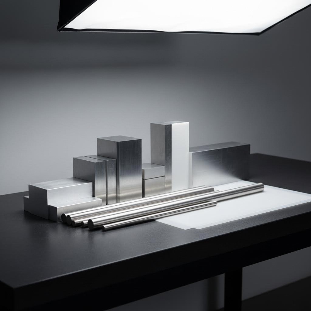
Unlike 3D printing, which builds parts layer by layer (additive manufacturing), or injection molding, which forces material into a mold (formative manufacturing), CNC machining takes a different approach. You start with more material than you need—a solid block, rod, or sheet—and strategically remove everything that isn't your final part.
This subtractive approach offers distinct advantages for machining parts:
- Material integrity: Working from solid stock maintains the material's inherent structural properties, unlike layered or molded processes
- Precision at scale: CNC machines achieve tolerances between 0.0002 to 0.0005 inches for critical dimensions
- Material versatility: From aluminum and stainless steel to engineering plastics and titanium, the process adapts to your material needs
- Repeatability: Industrial CNC machinery offers repeatability indices around ±0.0005 inches, producing near-identical parts batch after batch
Understanding what each part machine is capable of producing helps you design smarter from the start. A 3-axis mill excels at flat surfaces and pockets. A 5-axis machine can reach complex angles without repositioning. A CNC lathe produces cylindrical components with external and internal features like threads and tapers. Matching your design to the right machine capability isn't just about what's possible—it's about what's cost-effective.
This connection between machine capabilities and achievable results is exactly where most cost overruns begin. When you understand the fundamentals of how cnc machining parts are created, you can make design decisions that work with the process rather than against it—saving time, reducing waste, and keeping your budget intact.
CNC Machine Types and Their Part Capabilities
Now that you understand how cnc machining parts are created, the next question is simple: which machine should make your part? The answer directly affects your achievable tolerances, surface finish quality, and ultimately your project cost. Choosing the wrong machine type is like using a sledgehammer to hang a picture frame—you might get results, but they won't be pretty or economical.
Each CNC machine type excels at specific geometries and part configurations. Understanding these capabilities helps you design parts that leverage machine strengths rather than fighting against limitations. Let's break down the primary options and what each brings to the table.
Milling Machines for Complex Geometries
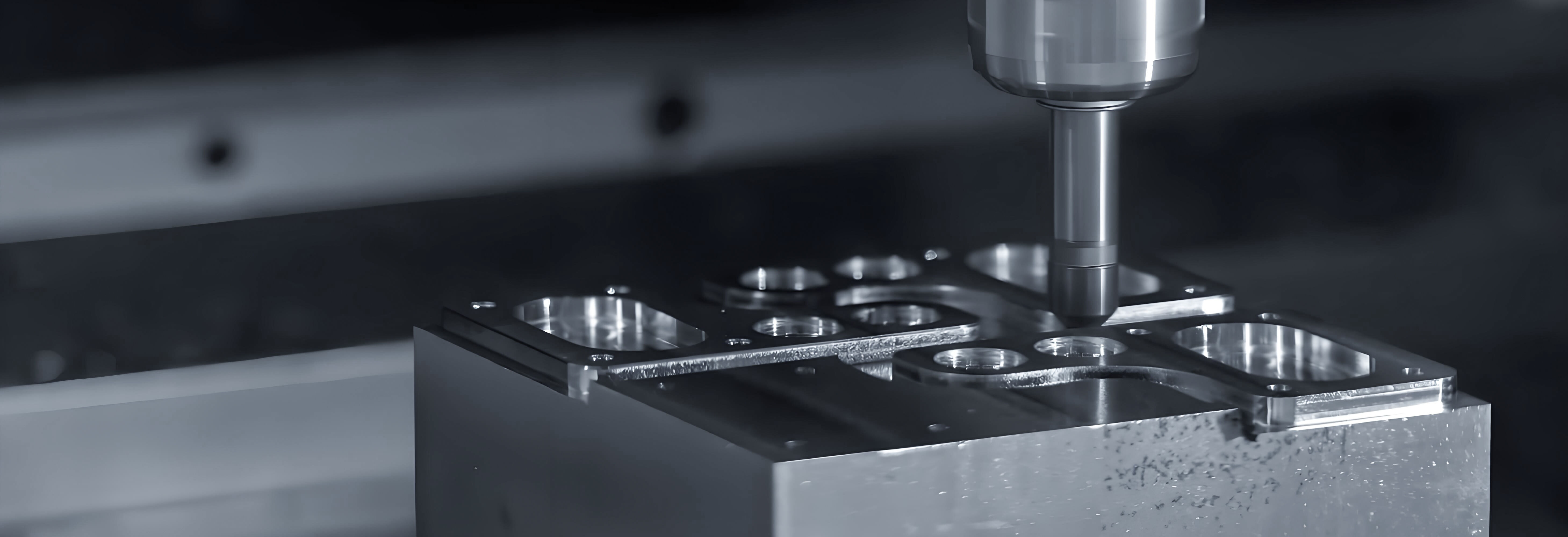
CNC milling machines use rotating cutting tools to remove material from a stationary workpiece. They're the workhorses of the machining world, capable of producing everything from simple brackets to intricate aerospace components. The key differentiator among milling machines? The number of axes they operate on.
A 3-axis CNC mill moves along three linear directions: X (left-right), Y (front-back), and Z (up-down). According to CNC Cookbook, these machines are widely used in manufacturing and can produce basic parts in 2.5 dimensions. They're ideal for flat surfaces, pockets, slots, and features accessible from the top of your workpiece. Think mounting plates, enclosures, and simple structural components.
When your cnc milling parts require features on multiple faces or complex angles, you'll need more axes. A 5-axis CNC machine adds two rotational axes, allowing the cutting tool to approach the workpiece from virtually any angle. This capability enables:
- Machining complex contoured surfaces in a single setup
- Accessing undercuts and deep cavities without repositioning
- Reducing the number of setups, which improves accuracy and reduces costs
- Producing aerospace and medical components with intricate geometries
The trade-off? 5-axis machines command higher hourly rates due to their complexity and programming requirements. If your part can be produced on a 3-axis machine, you'll typically save 20-40% on machining costs.
Turning Centers for Rotational Parts
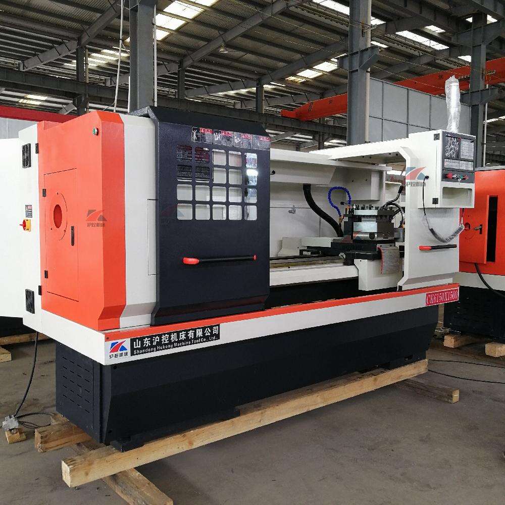
While milling machines rotate the tool, CNC lathes flip the script—they spin the workpiece while a stationary cutting tool shapes it. This makes cnc turning service the go-to choice for cylindrical components like shafts, bushings, threaded fasteners, and any part with rotational symmetry.
CNC lathes typically operate on two primary axes: the Z-axis controls tool movement along the workpiece length, while the X-axis moves perpendicular to the chuck. This configuration excels at producing external features like tapers and grooves, as well as internal operations such as boring and threading.
As noted by CNC Cookbook, CNC lathes are most suitable for producing cylindrical, conical, or flat shapes. If your part requires features beyond rotational symmetry—like off-center holes or milled flats—many modern turning centers include live tooling capabilities, combining turning and milling operations in one setup.
Wire EDM for Precision Cutting
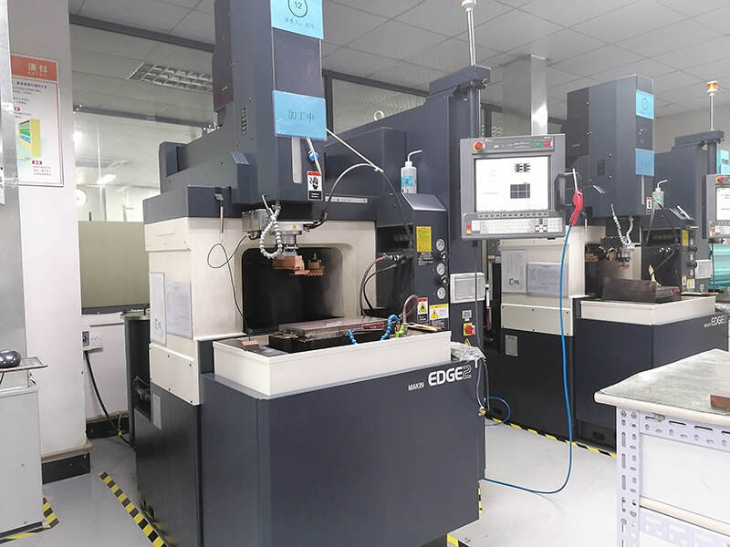
Sometimes conventional cutting tools simply won't work. When you need intricate cuts in hardened steel, titanium, or other difficult-to-machine materials, wire edm machining offers a solution that doesn't rely on mechanical cutting forces.
Wire discharge machining uses a thin electrically charged wire (typically 0.004" to 0.012" diameter) to erode material through controlled electrical sparks. The electrical discharge machine creates a precisely controlled gap between the wire and workpiece, vaporizing material with remarkable accuracy.
Wire edm excels in applications where traditional machining falls short:
- Cutting hardened tool steels after heat treatment
- Producing sharp internal corners impossible with rotating tools
- Achieving extremely tight tolerances (±0.0001" is achievable)
- Manufacturing extrusion dies, blanking punches, and precision molds
According to industry sources, edm wire edm technology is particularly effective for creating metal components and tools, with regular use in automotive, aerospace, and electronics manufacturing. The limitation? It only works with electrically conductive materials, and cutting speeds are slower than conventional machining.
| Machine Type | Best For | Typical Tolerances | Ideal Part Shapes |
|---|---|---|---|
| 3-Axis CNC Mill | Flat surfaces, pockets, simple features | ±0.005" (0.127mm) | Prismatic parts, brackets, plates |
| 5-Axis CNC Mill | Complex contours, multi-face features | ±0.002" (0.05mm) | Aerospace components, impellers, medical implants |
| CNC Lathe | Cylindrical components, threads | ±0.003" (0.076mm) | Shafts, bushings, pins, threaded parts |
| Wire EDM | Hard materials, intricate profiles | ±0.0001" (0.0025mm) | Dies, punches, gears, complex internal features |
The relationship between cnc machine parts selection and final part quality cannot be overstated. A part designed for 5-axis machining but produced on a 3-axis machine will require multiple setups, each introducing potential errors and adding cost. Conversely, a simple bracket that could be made on a basic 3-axis mill doesn't benefit from 5-axis capabilities—you're just paying premium rates for no added value.
Understanding which machine type aligns with your part geometry is the first step toward cost optimization. The next consideration? Designing your parts to work within each machine's capabilities from the start.
Design Guidelines for Optimal CNC Machined Parts
Sounds complex? Here's the reality: the decisions you make at the design stage determine up to 70% of your final manufacturing cost. A feature that looks simple on screen might require specialty tooling, multiple setups, or painfully slow feed rates to produce. Understanding design-for-manufacturability (DFM) principles transforms your cnc machined parts from cost headaches into efficiently produced components.
The challenge? According to Hubs, no industry-wide specific standards exist for CNC machining design. Machine and tool manufacturers continuously improve capabilities, expanding the limits of what's possible. However, following proven guidelines keeps your custom machined parts within cost-effective territory while maintaining the quality you need.
Critical Dimensions and Tolerance Planning
Every dimension on your part carries a tolerance—whether you specify one or not. When tolerances aren't called out, manufacturers apply standard grades like ISO 2768 medium or fine. But here's where costs sneak up on you: tighter tolerances require slower machining speeds, more precise equipment, and additional inspection time.
For precision cnc machining services, these tolerance guidelines keep parts manufacturable:
- General tolerances: ±0.1 mm (±0.004") is typical for most features; achievable tolerances can reach ±0.02 mm (±0.0008") when required
- Hole diameters: Use standard drill bit sizes whenever possible; non-standard diameters require end mill machining at higher cost
- Thread specifications: M6 or larger threads are recommended; smaller threads down to M2 are feasible but increase tap breakage risk
- Thread depth: 3 times the nominal diameter provides full strength; depths beyond this add cost without structural benefit
- Minimum hole diameter: 2.5 mm (0.1") for standard machining; anything smaller enters micro-machining territory requiring specialty tools
Wall thickness requirements vary significantly by material. As Jiga notes, minimum wall thickness should be 0.8 mm in metals and 1.2 to 4 mm in plastics depending on rigidity and strength. Why the difference? Thinner walls reduce material stiffness, increasing vibrations during machining and lowering achievable accuracy. Plastics face additional challenges—residual stresses can cause warping, and heat buildup may soften the material mid-cut.
For cnc milled parts, these wall thickness rules apply:
- Metal parts: 0.8 mm recommended minimum; 0.5 mm feasible but requires careful evaluation
- Plastic parts: 1.5 mm recommended minimum; 1.0 mm feasible with rigid engineering plastics
- High aspect ratios: Tall, thin walls dramatically increase chatter risk, requiring slower feeds and shallower cuts
Corner Radii and Cavity Depth Requirements
When you examine the parts of a cnc mill, you'll notice the cutting tools are cylindrical. This geometry creates an unavoidable reality: internal corners always have a radius matching or exceeding the tool diameter. Designing sharp 90-degree internal corners? Your machinist will need to use progressively smaller tools, dramatically increasing cycle time.
Follow these guidelines for cnc milling components to optimize corner and cavity features:
- Internal vertical corner radius: At least ⅓ times the cavity depth; larger radii allow bigger tools and faster machining
- Floor radius: 0.5 mm or 1 mm preferred; flat floors are also acceptable with standard end mills
- Cavity depth: Limit to 4 times cavity width for standard tooling; deeper cavities increase tool deflection and vibration
- Deep cavity machining: Depths up to 6 times tool diameter require specialized tooling; maximum achievable is approximately 30:1 ratio
Here's a precision cnc milling tip that saves money: increasing corner radii slightly above the minimum allows the tool to follow a circular path instead of stopping at sharp 90-degree turns. This produces better surface finishes and reduces machining time. If you absolutely need sharp internal corners, consider T-bone undercuts as an alternative.
Avoiding Common Design Pitfalls
Undercuts represent one of the most misunderstood features in CNC machining. These are areas where standard tools can't access material directly from above. While specialized T-slot and dovetail cutters exist, they add setup time and cost. When designing undercuts:
- T-slot widths: Use standard sizes between 3 mm and 40 mm; whole millimeter increments preferred
- Dovetail angles: 45-degree and 60-degree tools are standard; other angles require custom tooling
- Internal wall clearance: Add space equal to at least 4 times the undercut depth between the machined wall and any other internal wall
Machine setups represent another hidden cost driver. Every time the workpiece must be rotated and recalibrated, manual work increases total machining time. According to Hubs, rotating a part up to three or four times is often acceptable, but anything beyond this limit becomes excessive.
For maximum relative positional accuracy between features, design them to be machined in the same setup. Each recalibration introduces small but non-negligible errors that compound across your part.
Text and marking specifications also affect manufacturability. Engraved text removes less material than embossed text, making it the preferred choice. Use sans-serif fonts like Arial or Verdana at size 20 or larger—many CNC machines have pre-programmed routines for these standard fonts, eliminating custom programming time.
The bottom line? Design your parts to use the largest possible tool diameter and shortest tool length that still achieves your geometry. This single principle reduces cycle time, improves surface finish, and keeps your cnc machining parts costs under control. Material selection amplifies these design decisions—choosing the right material for your application determines which design rules apply and what tolerances are realistically achievable.
Material Selection for CNC Machined Components
You've optimized your design. You've selected the right machine type. Now comes a decision that can make or break your project budget: material selection. The material you choose for your cnc machined components doesn't just determine part performance—it directly impacts machining time, tool wear, achievable tolerances, and final cost per piece.
Here's what many engineers overlook: a material's machinability rating affects everything downstream. According to DEK, highly machinable materials take less time and power, resulting in reduced tool wear and refined surface finishes. Choosing a difficult-to-machine material without understanding the implications? You're signing up for longer cycle times, more frequent tool changes, and a bigger invoice.
Let's break down the most common material categories and what each brings to your precision cnc parts.
Aluminum and Its Machining Advantages
When it comes to metal parts machining, aluminum stands as the go-to choice for good reason. It's lightweight, corrosion-resistant, and machines like butter compared to steel or titanium. But not all aluminum alloys perform equally—each grade offers distinct trade-offs between strength, machinability, and cost.
For custom aluminum machining projects, these alloy grades dominate the industry:
- 6061 (3.3211): The workhorse alloy containing magnesium and silicon. With tensile strength around 180 MPa, it's ideal for structural applications like aerospace parts, machine components, and rail coaches. Heat treatable with excellent weldability.
- 7075 (3.4365): Zinc is the primary alloying element here, delivering high strength (570 MPa tensile), toughness, and exceptional fatigue resistance. According to Xometry, this grade is extensively used in aircraft structural parts where strength-to-weight ratio is critical.
- 2011 (3.1645): A free-machining alloy with 4-5% copper content. Perfect for high-speed machining and threading, commonly used for machine parts, bolts, and nuts. The trade-off? Low weldability and reduced corrosion resistance.
Aluminum cnc service providers typically achieve tolerances of ±0.005" (0.127mm) as standard, with ±0.002" (0.05mm) feasible for critical dimensions. The material's low density means less cutting force is required, enabling faster feed rates and reduced cycle times compared to steel.
Steel Grades for Demanding Applications
When your cnc components need to handle heavy loads, resist wear, or maintain structural integrity under stress, steel becomes the material of choice. Stainless steel cnc machining services are particularly valuable for parts requiring corrosion resistance in harsh environments.
The steel grades you'll encounter most frequently include:
- 1018/S235 (1.0038): Hot-rolled structural steel with good plasticity and weldability. Lower yield strength (235 MPa) but excellent formability for channels, plates, and angle bars.
- 1045/C45 (1.0503): Medium carbon steel offering 630 MPa tensile strength. Ideal for screws, shafts, and drills where wear resistance matters. Low thermal conductivity means heat management during machining is critical.
- 304 Stainless (1.4301): Chromium-nickel austenitic steel with 590 MPa tensile strength. Excellent corrosion resistance and formability make it perfect for kitchen equipment, tubes, and sinks. According to Xometry, it has good machinability but low thermal conductivity—plan for appropriate coolant use.
- 316L Stainless (1.4404): Molybdenum addition provides improved resistance to chlorides and non-oxidizing acids. Used extensively in food processing, marine applications, and medical devices.
Steel machining requires different parameters than aluminum. Slower cutting speeds, more rigid setups, and carbide tooling become necessary. Expect tolerances around ±0.003" (0.076mm) standard, though ±0.001" is achievable with precision grinding operations.
Engineering Plastics in CNC Production
Metal isn't always the answer. Engineering plastics offer unique advantages for cnc machined components—lightweight construction, electrical insulation, chemical resistance, and often lower material costs. As JLCCNC notes, plastics have become as common as metals in CNC production.
However, plastic machining demands different strategies. Lower melting points, higher thermal expansion, and different chip behaviors require adjusted feeds, speeds, and tooling. The right plastic depends entirely on your application requirements:
- Delrin/POM: The easiest plastic to machine with excellent dimensional stability and zero porosity. Self-lubricating properties make it ideal for bushings, gears, and electrical parts. Tolerances of ±0.002" are achievable.
- ABS: Tough with good wear resistance and improved surface finish. Excellent for prototypes and consumer products. Watch for water absorption and poor resistance to strong acids.
- PEEK: The premium choice for demanding applications. Withstands high temperatures and aggressive chemicals while maintaining exceptional strength. According to Xometry, PEEK is used extensively in medical, aerospace, and automotive components.
- Acrylic: Offers glass-like clarity and brilliance for display cases and optical applications. Highly fragile—cast blanks machine better than extruded sheets.
- Teflon/PTFE: Extremely low friction and excellent chemical resistance. The challenge? High thermal expansion and stress creep make tight tolerances difficult to maintain.
For plastic parts, minimum wall thickness should be 1.5mm compared to 0.8mm for metals. According to JLCCNC, tolerances of ±0.05mm or better are achievable with proper fixturing and tool selection.
| Material | Key Properties | Common Applications | Machining Considerations |
|---|---|---|---|
| Aluminum 6061 | Lightweight, corrosion resistant, 180 MPa tensile | Aerospace structures, machine parts, automotive | High speed cutting, excellent chip evacuation, standard tooling |
| Aluminum 7075 | High strength (570 MPa), fatigue resistant | Aircraft structural parts, high-stress components | Requires sharp tools, watch for work hardening |
| 304 Stainless | Corrosion resistant, 590 MPa tensile, formable | Food equipment, medical devices, marine hardware | Low thermal conductivity, requires coolant, carbide tooling |
| 316L Stainless | Chloride resistant, marine grade corrosion resistance | Chemical processing, marine, implants | Similar to 304 but slightly more difficult, premium pricing |
| Delrin/POM | Dimensionally stable, self-lubricating, easy to machine | Bushings, gears, electrical components | Excellent machinability, low cutting forces |
| PEEK | High temperature, chemical resistant, strong | Aerospace, medical implants, automotive seals | Requires sharp tools, higher material cost |
| Titanium Grade 5 | Exceptional strength-to-weight, biocompatible | Medical implants, aerospace, marine | Low thermal conductivity, requires rigid setup, slow speeds |
Material selection directly influences your achievable tolerances. Aluminum and brass hold tight tolerances easily. Stainless steel requires more careful process control. Plastics need thermal management to prevent dimensional changes during machining. Matching your material choice to your tolerance requirements—not the other way around—keeps costs predictable and quality consistent.
Of course, material selection doesn't happen in isolation. Different industries impose specific requirements that influence both material choices and the certifications your manufacturing partner must hold.
Industry Applications and Certification Requirements
When you're sourcing cnc machining parts, the industry you serve changes everything. A bracket destined for a consumer electronics enclosure faces completely different requirements than one going inside a jet engine. Each sector brings unique tolerance demands, material restrictions, and certification hurdles that directly impact your design decisions and manufacturing costs.
Here's what catches many engineers off guard: certifications aren't just paperwork. According to American Micro Industries, certified processes mean the methods and equipment themselves are held to documented standards, promoting consistency from one batch to the next. The result is a significant reduction in defects, rework, and material waste. Understanding what each industry demands helps you choose the right cnc service—and avoid costly surprises when your parts don't meet sector-specific requirements.
Automotive Component Requirements
The automotive sector demands consistent, defect-free parts at scale. When you're producing thousands of identical components, even minor variations compound into major quality issues. This is where IATF 16949 certification becomes non-negotiable for serious contract machining services.
IATF 16949 combines ISO 9001 principles with automotive-specific requirements for continuous improvement, defect prevention, and stringent supplier oversight. As noted by American Micro Industries, compliance with IATF 16949 can boost a manufacturer's credibility and open the door to business with leading manufacturers that mandate the highest levels of part quality and supply chain reliability.
- Tolerance expectations: Typically ±0.05mm for functional surfaces; ±0.1mm for general dimensions
- Traceability requirements: Full material certification and process documentation for every batch
- Surface finish standards: Ra 1.6 to 3.2 μm for most machined surfaces; bearing surfaces may require Ra 0.8 μm
- Production volume considerations: Design for high-volume manufacturing with minimal setup changes
When searching for machining services near me for automotive applications, prioritize shops with demonstrated IATF 16949 certification and Statistical Process Control (SPC) systems. These capabilities ensure your cnc machining part maintains consistent quality across production runs.
Medical Device Precision Standards
Precision takes on life-or-death significance in medical device manufacturing. A prosthetic component that's off by even a fractional measurement could cause pain, device failure, or require surgical replacement. According to Micro-Matics, some medical devices are implanted into the human body, and any margin of error could cause these units to fail.
The regulatory framework for medical CNC machining includes:
- ISO 13485: The definitive quality management standard outlining strict controls over design, manufacturing, traceability, and risk mitigation
- FDA 21 CFR Part 820: U.S. Quality System Regulation governing product design, manufacturing, and tracking
- Biocompatibility requirements: Materials must be certified for human contact; titanium, 316L stainless steel, and PEEK dominate implant applications
- Documentation standards: Every process step must be documented for regulatory audit and product traceability
As Micro-Matics emphasizes, integrating FDA and ISO compliance into the design phase of each component is essential to the success of each product engineered and created. This means starting with smart prototypes and choosing materials that meet or exceed regulations while working well within the machining process.
Medical tolerances often reach ±0.0005" (0.0127mm) for critical implant dimensions. Surface finish requirements frequently specify Ra 0.4 to 0.8 μm for articulating surfaces. Swiss machining often rises to the top for medical components, offering up to thirteen axes for the expanded precision these applications demand.
Aerospace-Grade Specifications
Aerospace machining imposes the most rigorous standards in manufacturing. According to Yijin Hardware, modern aircraft contain between 2 and 3 million precision-machined parts, each requiring rigorous quality control. Components must maintain structural integrity under extreme conditions—temperature variations from -65°F to +350°F (-54°C to +177°C) are standard operating parameters.
Key aerospace certification requirements include:
- AS9100: Extends ISO 9001 with 105 additional aerospace-specific requirements covering risk management, stringent documentation, and product integrity control
- NADCAP accreditation: Required for special processes like heat treating, chemical processing, and nondestructive testing
- Material traceability: Complete chain-of-custody documentation from raw material to finished component
- First Article Inspection (FAI): Comprehensive validation of initial production parts against design specifications
Aviation CNC machining demands significantly tighter tolerances than standard industrial processes. While typical machine shops work with ±0.005 inches, aerospace precision machining consistently achieves ±0.0001 inches or better. Surface roughness requirements typically specify 16-32 μin Ra for aerodynamic surfaces and 4-8 μin Ra for bearing surfaces.
Custom cnc machining services for aerospace must demonstrate robust quality systems through third-party audits. As noted in aerospace industry standards, components must perform perfectly in environments not encountered elsewhere—including high temperatures exceeding 2000°F and pressure variations from 0.2 atm to 1.2 atm during flight.
Robotics and Automation Considerations
Robotics applications bridge multiple industry requirements while adding unique challenges around weight optimization and precision motion. Components must deliver maximum strength with minimum mass while maintaining the geometric accuracy required for repeatable automated movements.
- Tolerance requirements: ±0.025mm typical for motion components; tighter for precision positioning systems
- Material priorities: Aluminum alloys for weight-critical structures; hardened steels for wear surfaces and gears
- Surface finish considerations: Ra 0.8 to 1.6 μm for sliding surfaces; anodized finishes for corrosion protection
- Design for assembly: Consistent datum surfaces and standardized fastener patterns reduce integration complexity
Robotics components often require the flexibility of precision machining service providers who can handle both prototype development and production scaling. The iterative nature of robotics development means your manufacturing partner should support rapid design changes without excessive setup costs.
Understanding these industry-specific requirements before you begin design work prevents costly redesigns and certification delays. Your choice of contract machining services should align with your target industry's certification requirements—selecting a shop certified only to ISO 9001 for aerospace work will create problems downstream, no matter how competitive their pricing appears.
With industry requirements clarified, the next question becomes practical: what factors actually drive your per-part costs, and how can you optimize them without sacrificing the quality your application demands?
Cost Factors and Lead Time Considerations
You've designed your part, selected your material, and identified a capable manufacturer. Now comes the moment of truth: the quote arrives, and it's significantly higher than expected. Sound familiar? Understanding what drives cnc machining parts costs gives you the power to make informed trade-offs—reducing expenses without sacrificing the functionality your application demands.
Here's what most buyers don't realize: machining time is the single largest cost driver, often outweighing material costs, setup fees, and surface finishing combined. According to Scan2CAD, the machining time is considered the most significant cost driver during machining—so great, in fact, that it outweighs the setup costs, material costs, and costs of achieving custom finishes through plating or anodizing. Every design decision you make either extends or shortens that time at the machine.
What Drives CNC Machining Costs
When you request a cnc quote online, manufacturers calculate pricing based on a hierarchy of cost factors. Understanding this hierarchy helps you prioritize where to focus your optimization efforts:
- Machining time: The dominant factor—every minute your part occupies the spindle translates directly to cost. Complex geometries, tight tolerances, and deep cavities all extend cycle time
- Setup and programming: Fixed costs that apply whether you're making one part or one hundred. Includes CAM programming, fixture preparation, tool loading, and first-article inspection
- Material costs: Raw material pricing plus the reality that CNC machining wastes 30% to 70% of the original blank volume as chips
- Tooling expenses: Cutting tools, inserts, and work-holding components all have limited lifespans and must be replaced periodically
- Labor costs: Skilled operators for programming, setup, quality control, and machine monitoring
- Overhead: Facility costs, utilities, equipment depreciation, and administrative expenses distributed across all jobs
Part complexity influences costs in ways that aren't immediately obvious. As Geomiq notes, complex parts with intricate geometries typically require continual repositioning of the workpiece to grant the cutting tool access to different areas, thereby increasing machining time. Each repositioning adds setup time, introduces potential alignment errors, and extends your lead time.
Tolerance requirements create another cost multiplier. While standard tolerances of ±0.127mm add minimal expense, specifying tighter tolerances demands slower feed rates, shallower cuts, and more frequent inspection. According to Xometry, if your design is complex and has tight tolerances, you can expect to pay more because intricacies like these require more advanced machining techniques, specialized tooling, and longer machining times.
Surface finish specifications follow the same pattern. The standard 3.2 μm Ra finish comes at baseline cost. According to Geomiq, achieving smoother finishes of 1.6 μm, 0.8 μm, and 0.4 μm Ra adds approximately 2.5%, 5%, and up to 15% above the base price, respectively. These finer finishes require slower speeds, shallower passes, and sometimes post-machining polishing operations.
Optimizing Design for Cost Efficiency
The most effective cost reduction happens before you ever submit an online machining quotes request. Design decisions made early lock in the majority of your manufacturing costs. Here's how to design with cost efficiency in mind:
Simplify wherever possible. As Geomiq recommends, reduce CNC machining costs by simplifying your design, incorporating complex features only when required for functionality. Every additional feature adds programming time, tool changes, and machining cycles. If a feature doesn't serve a functional purpose, eliminate it.
Specify tolerances strategically. Apply tight tolerances only to critical mating surfaces and functional interfaces. According to Geomiq, the default tolerance of ±0.127mm is already quite accurate and sufficient for most applications. Blanket tight tolerances across your entire part dramatically increase cost without improving functionality.
Design for standard tooling. Internal corner radii should accommodate common end mill diameters. Hole sizes should match standard drill bits. Thread specifications should use common sizes like M6 or larger. Custom tooling adds both cost and lead time.
Minimize setups. Design parts that can be machined in as few setups as possible. Each time the workpiece requires repositioning, manual labor increases and alignment precision decreases. Parts designed for single-setup machining cost less and achieve better feature-to-feature accuracy.
The Batch Size Equation
Quantity has a dramatic effect on per-unit cost—but not always in the direction you'd expect. For small batch cnc machining, setup costs dominate your per-part pricing. As Geomiq illustrates, a single part might cost £134, while ten units cost £385 total (£38 each), and one hundred units cost £1,300 total (£13 each). That represents a 90% reduction in per-unit cost simply by increasing quantity.
This pricing structure creates important strategic considerations:
- Prototyping: Accept higher per-part costs during development; focus on design validation rather than cost optimization
- Low volume cnc machining: Consider ordering slightly higher quantities than immediately needed if storage isn't an issue
- Production cnc machining: Leverage economies of scale through larger batch orders; setup costs become negligible per part
- Rapid cnc requirements: Expedited lead times command premium pricing—plan ahead when possible to avoid rush charges
Lead time itself functions as a cost lever. According to Xometry, short lead times drive cost due to overtime and expedites on material and finishing. Rapid machining requests force manufacturers to interrupt scheduled jobs, pay overtime labor, and expedite material procurement—all of which get passed through to your invoice.
For production planning, consider the relationship between design complexity and lead time. Complex parts with multiple setups, specialized tooling, or tight tolerances require more scheduling flexibility. Simpler designs flow through the shop faster and with more predictable delivery dates.
The bottom line? Every design decision carries a price tag. Understanding these cost drivers transforms your approach from reactive—surprised by quotes—to proactive, making informed trade-offs that balance functionality, quality, and budget from the start. But CNC machining isn't your only option. Knowing when alternative manufacturing methods make better sense can save you even more.
CNC Machining vs Alternative Manufacturing Methods
CNC machining delivers exceptional precision and material integrity—but it's not always the most cost-effective solution for every project. Sometimes a completely different manufacturing method will get you better results at a fraction of the cost. The question isn't which process is "best" in absolute terms. It's which process is best for your specific part, quantity, and timeline.
According to Xometry, CNC machining and 3D printing are direct competitors for the creation of solid parts, among their biggest differences being that one method works by removing material while the other adds it layer by layer. Understanding when each approach makes sense helps you avoid paying premium prices for capabilities you don't actually need.
Let's examine how CNC machining stacks up against the primary alternatives—and when you should consider switching methods entirely.
CNC vs 3D Printing Decision Points
The additive versus subtractive debate often comes down to three factors: geometry, quantity, and material requirements. Rapid cnc prototyping excels when you need functional parts in engineering-grade materials with tight tolerances. 3D printing wins when geometric complexity would make machining prohibitively expensive.
According to Xometry, 3D printing delivers net shape parts quickly, whereas CNC machining requires individual setup and generally manual programming plus supervision. It's common for CNC components to cost 5 to 10 times the price of 3D printed parts for simple geometries. However, that cost equation flips when precision and material properties become critical.
Here's where each method shines:
- Choose 3D printing when: You need complex internal geometries, lattice structures, or organic shapes that would require extensive multi-axis machining. Prototype machining services become expensive when parts need features accessible only from difficult angles.
- Choose CNC machining when: Material strength matters. According to Xometry, various 3D printing processes offer varied strength compared with native material properties—as low as 10% of material tensile strength for FFF in ABS. CNC-machined parts deliver undisturbed native material properties.
- Consider surface finish requirements: 3D printing is generally affected by process mechanics concerning surface finish. Z-resolution in particular creates stepped surfaces and visual disruptions. CNC surface finish is uniform and can be extremely precise when cutter paths are programmed accordingly.
Speed comparisons require context. According to Xometry, preparation for 3D printing requires little time before a print can commence, with most prints completing within hours. CNC machining requires skilled preparation of programming for cutter selection and cutter path, often requiring custom jigs. Total time for preparation and machining can run into a day or more depending on complexity.
For edm machining applications—particularly when working with hardened materials or intricate profiles—neither standard 3D printing nor conventional milling competes effectively. What is electric discharge machining? It's a specialized process using electrical sparks to erode material, achieving tolerances impossible with either additive or conventional subtractive methods. Types of electric discharge machining include wire EDM and sinker EDM, each suited to specific geometries. While edm machinery commands premium rates, it remains irreplaceable for certain precision applications.
When Injection Molding Makes Sense
Injection molding enters the conversation when quantity increases dramatically. According to Protolabs, injection molding is ideal for high-volume production and complex geometries with detailed features and material variety. The catch? Tooling costs create a significant upfront investment.
The break-even analysis typically works like this:
- 1 to 50 parts: CNC machining or 3D printing almost always wins on total cost
- 50 to 500 parts: Consider rapid injection molding with aluminum tooling; per-part costs drop significantly
- 500 to 5,000+ parts: Steel injection mold tooling becomes economically justified; per-part costs approach cents rather than dollars
According to Protolabs, injection molding offers consistency, repeatability, and a massive number of materials to choose from—advantages that compound across high-volume production runs. However, design changes after tooling is cut become extremely expensive.
For electric discharge machining of mold components themselves, EDM becomes essential. Complex cavity geometries and sharp internal corners in hardened tool steel require wire or sinker EDM to achieve the precision injection molding demands.
Casting Considerations
Casting occupies a unique position in the manufacturing spectrum. According to The Steel Printers, casting would be the cheaper option when producing many parts, while smaller orders with complex requirements favor other methods. This is because casting benefits from higher economies of scale—the fixed cost of producing a casting mold can be allocated across many parts.
Key casting decision factors include:
- Part size: Casting excels at producing large parts that would require extensive machining time or exceed 3D printer build volumes
- Quantity requirements: According to The Steel Printers, casting becomes the most suitable method for quantities in the thousands
- Post-processing needs: Cast parts often require secondary machining to achieve final tolerances on critical surfaces
- Material density: LPBF 3D printed parts generally outperform cast parts thanks to higher densities and reduced risk of internal voids
The hybrid approach—casting near-net shapes followed by precision CNC finishing—often delivers the best cost-to-quality ratio for medium to high volumes with demanding tolerance requirements.
Manufacturing Method Comparison
| Method | Best Quantity Range | Tolerance Capability | Material Options | Typical Lead Time |
|---|---|---|---|---|
| CNC Machining | 1 to 1,000 parts | ±0.005" standard; ±0.0005" precision | All engineering metals and plastics | 1 to 10 days depending on complexity |
| 3D Printing (FDM/SLS) | 1 to 100 parts | ±0.005" to ±0.015" | Limited polymers and metal powders | 1 to 5 days |
| Injection Molding | 500 to 100,000+ parts | ±0.002" to ±0.005" | Wide range of thermoplastics | 2 to 8 weeks (includes tooling) |
| Metal Casting | 100 to 10,000+ parts | ±0.010" to ±0.030" | Most castable metals and alloys | 4 to 12 weeks (includes tooling) |
| Wire EDM | 1 to 500 parts | ±0.0001" achievable | Electrically conductive materials only | 3 to 14 days |
According to The Steel Printers, there's no method that always comes out above another—to progress in the future, traditional manufacturing techniques and newer methods will complement each other, filling gaps where the other falls short.
The practical takeaway? Match your manufacturing method to your actual requirements. A part designed for CNC machining might cost 10 times more than necessary if 3D printing would satisfy your functional needs. Conversely, specifying 3D printing for a load-bearing component that needs full material strength could lead to field failures.
When considering your project, think about quantity, complexity, cost, and timeline together. The right answer emerges from balancing all four factors against your specific application requirements. Once you've selected the appropriate manufacturing method, ensuring consistent quality across your production run becomes the next critical focus.
Quality Control and Inspection Standards
You've selected the right manufacturing method, optimized your design, and found a capable shop. But here's a question that separates successful projects from costly failures: how do you know the parts you receive actually meet your specifications? Quality control isn't just about catching defects—it's about preventing them in the first place and verifying that every precision cnc machining parts order delivers consistent results.
According to FROG3D, the primary objective of quality control is to minimize errors by accurately identifying and addressing potential issues. Without robust inspection processes, defective parts can result in significant financial losses and a negative industry reputation. Let's examine the verification methods that keep your cnc prototype machining and production runs on track.
Dimensional Inspection Methods
Dimensional accuracy forms the foundation of quality verification. Even minor deviations can render a part unusable, particularly in precision industries like aerospace or medical devices. Modern inspection combines traditional measurement tools with advanced coordinate measuring technology.
Key dimensional inspection approaches include:
- Hand tools: Micrometers, calipers, and height gauges provide quick verification of critical dimensions during and after machining
- Coordinate Measuring Machines (CMM): According to FROG3D, CMMs provide precise and automated measurements for complex geometries and tight tolerances, utilizing both tactile and non-contact probes to capture dimensional data
- 3D scanning: Digital scanners create detailed surface maps, enabling comparison against CAD models to identify deviations across entire part geometries
- Go/no-go gauges: Fixed gauges provide rapid pass/fail verification for high precision machining services with critical hole diameters and thread specifications
For cnc machining prototyping work, CMM inspection often accompanies first-article reports. These detailed measurements verify that your initial parts conform to design intent before proceeding to production quantities. Precision cnc components destined for critical applications may require 100% inspection of key features.
Surface Finish Verification Standards
Surface finish directly impacts part functionality—from bearing surfaces that require specific roughness values to aesthetic components demanding mirror-like finishes. According to FROG3D, the condition of the cutting tool, material properties, and feed rate all influence the resulting surface finish, highlighting the importance of careful control during machining.
Surface roughness is typically measured in Ra (arithmetic average roughness), quantified in microinches or micrometers. Common verification methods include:
- Profilometers: Stylus-based instruments trace surface peaks and valleys to calculate precise roughness values
- Optical comparators: Visual comparison against reference standards for quick surface quality assessment
- Non-contact optical systems: Laser-based measurement for delicate surfaces or soft materials
Technical machining services should provide surface finish documentation when specifications call for controlled roughness values. For cnc machining services mw+ requirements, expect detailed surface maps showing Ra measurements at multiple locations.
Statistical Process Control in Production
When you're running production quantities, inspecting every single part becomes impractical. This is where Statistical Process Control (SPC) proves invaluable. According to Baker Industries, SPC is a data-driven method for monitoring and controlling CNC machining that helps identify trends, variations, and potential issues before they escalate into major problems.
Effective SPC implementation involves tracking key dimensions across production runs, establishing control limits, and responding immediately when measurements trend toward out-of-tolerance conditions. This proactive approach catches process drift before it produces defective parts.
Quality checkpoints throughout the CNC machining workflow should include:
- Incoming material inspection: Verify raw material certifications and dimensional conformance
- First-article verification: Complete dimensional inspection before production proceeds
- In-process monitoring: Regular sampling during production runs using SPC charts
- Final inspection: Comprehensive verification against drawing requirements
- Documentation review: Confirm all certifications, test reports, and traceability records are complete
What documentation should you expect from quality-focused manufacturers? At minimum: material certifications (mill test reports), dimensional inspection reports, and surface finish verification where specified. For precision cnc components in regulated industries, expect full traceability documentation linking your parts to specific material lots and machine operations.
The investment in robust quality systems pays dividends through reduced rework, fewer field failures, and consistent part performance. When evaluating potential manufacturing partners, their quality infrastructure tells you as much about future results as their machine capabilities.
Choosing the Right CNC Machining Partner
You've optimized your design, selected the right material, and established your quality requirements. Now comes a decision that will determine whether your project succeeds or becomes a cautionary tale: selecting the right cnc machining shop to bring your parts to life. The wrong choice means missed deadlines, rejected parts, and budget overruns. The right choice? A strategic partnership that scales with your needs from first prototype to full production.
According to Norck, a CNC machining service isn't just about owning fancy machines; it's about the knowledge and experience of the people operating them. Finding that ideal partner requires systematic evaluation across multiple dimensions—from technical capabilities to communication responsiveness.
Evaluating Manufacturing Capabilities
When comparing online cnc machining services, start with the fundamentals: can they actually make your part? This sounds obvious, but capability mismatches waste everyone's time. A shop specializing in high-volume automotive components may struggle with your complex aerospace prototype. Conversely, a prototype cnc machining specialist might lack the capacity for your 10,000-unit production run.
According to BOEN Rapid, a supplier equipped with advanced multi-axis machining centers, precision turning equipment, and automated inspection tools is more likely to deliver complex geometries with high accuracy. The integration of modern CAD/CAM software is equally important, as it determines how effectively designs are translated into finished parts.
Use this checklist when evaluating potential manufacturing partners:
- Machine fleet diversity: Do they have the right equipment for your part geometry—3-axis mills for simple prismatic parts, 5-axis for complex contours, CNC lathes for cylindrical components?
- Material expertise: Have they worked extensively with your specified material? Machining titanium requires different expertise than cutting aluminum or engineering plastics
- Tolerance capabilities: Can they consistently achieve your required tolerances? Request sample inspection reports from similar projects
- Inspection equipment: According to Norck, look for Coordinate Measuring Machines (CMMs), optical comparators, micrometers, calipers, and surface roughness testers. Advanced, regularly calibrated inspection tools demonstrate commitment to accuracy
- Quality certifications: ISO 9001 is baseline. Industry-specific certifications like IATF 16949 for automotive or AS9100 for aerospace indicate specialized expertise
- Production capacity: Can they handle your current order and scale up if demand increases?
Communication quality often predicts project success. According to Norck, responsiveness matters—how quickly do they respond to your inquiries and requests for quotes? A prompt and clear response often indicates professionalism and efficiency. Dedicated project managers, clear communication channels, and proactive updates help manage expectations and resolve issues swiftly.
From Prototype to Production Scale
Your manufacturing needs evolve. What starts as a single cnc prototyping service request often becomes recurring production orders. The partner you choose should support this entire journey without forcing you to re-qualify new suppliers at each stage.
According to Ensinger, successful CNC-machined components start with clearly defined project requirements. Engineers must consider functional performance, environmental conditions, and any regulatory or industry-specific standards that apply. Ensuring alignment on tolerances, surface finish, and mechanical performance upfront is critical to avoid costly adjustments later.
Here's what to look for at each production stage:
Rapid cnc machining and prototyping: Speed matters most here. You need custom cnc parts quickly to validate designs before committing to production tooling or processes. Look for partners offering cnc machining rapid prototyping with lead times measured in days, not weeks. The ability to iterate quickly—receiving feedback, modifying designs, and producing revised parts—accelerates your development cycle.
Low-volume production: As you transition from prototypes to initial production, consistency becomes critical. According to Ensinger, transitioning to low-volume production requires careful planning to maintain tight tolerances, repeatable quality, and full traceability. In-house quality assurance processes, including CMM inspection and detailed documentation, support this scale-up while ensuring consistency across batches.
Mass production: High-volume runs demand different capabilities—automated material handling, lights-out machining, and robust Statistical Process Control systems. Your partner should demonstrate capacity to maintain quality across thousands of identical parts without degradation.
Consider Shaoyi Metal Technology as an example of what to expect from a capable manufacturing partner. As an IATF 16949-certified facility, they offer precision CNC machining services spanning rapid prototyping to mass production. Their lead times as fast as one working day demonstrate the responsiveness quality manufacturers provide, while their strict SPC quality systems ensure consistency across production volumes. For automotive applications specifically, their automotive CNC machining solutions showcase the integration of certification, capability, and capacity that serious projects demand.
Partner Evaluation Checklist
Before committing to any cnc machining shop, systematically verify these critical factors:
- Technical capability alignment: Machine types, axis counts, and work envelope sizes match your part requirements
- Certification verification: Request copies of current certificates; verify through issuing bodies if supplying regulated industries
- Reference projects: Ask for case studies or references from similar applications in your industry
- Quote transparency: According to Norck, detailed quotes should clearly break down costs for materials, labor, tooling, finishing, and any other services. A transparent quote helps you understand where your money is going
- Lead time reliability: Request data on their average turnaround times and on-time delivery track record
- Scalability potential: According to BOEN Rapid, assessing production capacity is fundamental to ensuring your supplier can handle both current and future requirements
- Value-added services: Do they offer finishing, assembly, or inventory management that could streamline your supply chain?
- Communication infrastructure: Dedicated contacts, project management systems, and responsive technical support
According to Norck, while cost is always a factor, it should never be the only factor. The cheapest quote isn't always the most economical in the long run if it leads to rejected parts, missed deadlines, or rework. Consider the potential for a long-term relationship—a reliable precision CNC machining partner can become an invaluable extension of your team, understanding your needs and consistently delivering high-quality results across multiple projects.
The right manufacturing partner transforms your CNC machining parts from cost centers into competitive advantages. They catch design issues before they become production problems, suggest optimizations that reduce costs without sacrificing quality, and scale seamlessly as your business grows. Take the time to evaluate thoroughly—your future production runs depend on the partnership you build today.
Frequently Asked Questions About CNC Machining Parts
1. What are CNC machine parts?
CNC machine parts are custom-designed components produced through a subtractive manufacturing process where computerized controls guide cutting tools to remove material from solid workpieces. These parts achieve dimensional accuracy typically within ±0.005 inches and include everything from simple brackets to complex aerospace components. The process translates digital CAD designs into physical parts through automated G-code programming, ensuring consistent, repeatable results across production runs.
2. How much does it cost to get a part CNC machined?
CNC machining costs vary based on several factors. Hourly rates range from $50 to $150 depending on equipment complexity and precision requirements. Setup fees start at $50 and can exceed $1,000 for complex jobs. The primary cost drivers include machining time (the largest factor), material costs, tolerance requirements, and quantity. A single prototype might cost $134, while ordering 100 units could reduce per-part costs to $13—a 90% reduction through batch efficiency.
3. What tolerances can CNC machining achieve?
Standard CNC machining achieves tolerances of ±0.005 inches (0.127mm) for general features. Precision machining can reach ±0.002 inches (0.05mm), while wire EDM achieves ±0.0001 inches for critical applications. Tolerance capabilities vary by machine type: 3-axis mills deliver ±0.005 inches, 5-axis mills achieve ±0.002 inches, and CNC lathes typically hold ±0.003 inches. Material selection also affects achievable tolerances—aluminum holds tight tolerances easily while plastics require thermal management.
4. What materials can be CNC machined?
CNC machining works with a wide range of materials including aluminum alloys (6061, 7075), stainless steels (304, 316L), carbon steels, titanium, brass, and engineering plastics like Delrin, PEEK, ABS, and acrylic. Each material has specific machining considerations—aluminum machines quickly with excellent chip evacuation, while stainless steel requires slower speeds and carbide tooling. Material selection impacts machining time, tool wear, and achievable surface finishes.
5. How do I reduce CNC machining costs without sacrificing quality?
Reduce costs by simplifying designs, specifying tolerances only where functionally necessary (±0.127mm is sufficient for most applications), and designing for standard tooling. Increase internal corner radii to allow larger cutting tools, minimize the number of setups required, and order in larger batches to spread setup costs. IATF 16949-certified manufacturers like Shaoyi Metal Technology offer SPC quality systems that maintain consistency while optimizing production efficiency.