 Small batches, high standards. Our rapid prototyping service makes validation faster and easier —

CNC Cut Sheet Metal: Pick The Right Method Or Waste Thousands
Understanding CNC Sheet Metal Cutting Fundamentals
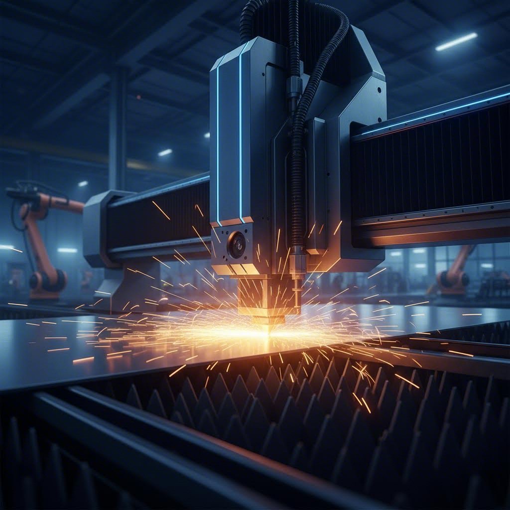
Ever wondered how manufacturers create those impossibly precise metal components you see in cars, aircraft, and electronics? The answer lies in CNC cut sheet metal technology—a process that has fundamentally transformed how we shape raw materials into functional parts.
What CNC Cutting Actually Means for Sheet Metal
Let's break down the cnc meaning first. CNC stands for Computer Numerical Control, a technology where computerized systems direct cutting tools with pinpoint accuracy. Instead of relying on manual operation, these machines interpret digital instructions and translate them into precise movements. The result? Repeatability and accuracy that human hands simply cannot match.
CNC cut sheet metal refers to the process of using computer-controlled machinery to precisely cut, shape, and fabricate flat metal sheets into custom components with tolerances as tight as 0.001 inches.
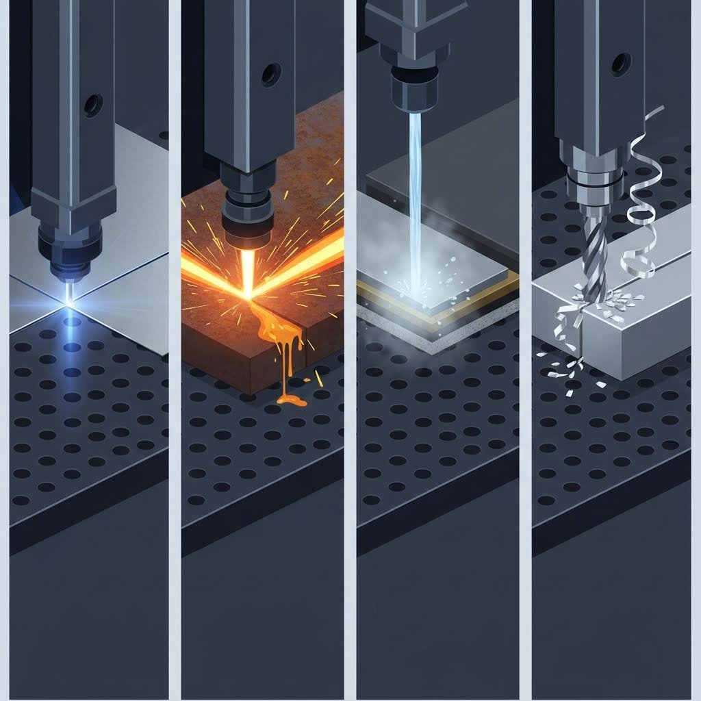
When you're working with cnc sheet metal processes, you'll encounter several primary cutting methods: laser cutting, plasma cutting, waterjet cutting, and CNC routing. Each approach offers distinct advantages depending on your material type, thickness requirements, and budget constraints. Choosing incorrectly between these methods can waste thousands of dollars on suboptimal results or unnecessary capabilities.
Why Precision Matters in Modern Metal Fabrication
Imagine assembling a complex product where components don't fit together properly. In sheet metal fabrication, even minor deviations can cascade into major problems—parts that won't assemble, structural weaknesses, or complete project failures.
Modern metal fabrication demands tolerances that traditional methods cannot achieve. A laser cutter can maintain accuracy within fractions of a millimeter across hundreds of identical parts. This consistency matters whether you're producing prototype components or running full-scale production.
The gap between hobbyist understanding and industrial applications often comes down to appreciating this precision requirement. While a weekend project might tolerate some variation, professional applications require the reliability that only CNC technology delivers. Throughout this guide, you'll discover exactly how to match cutting methods to your specific needs—preventing costly mistakes before they happen.
Comparing CNC Cutting Methods for Sheet Metal
Now that you understand the fundamentals, here's where the real decision-making begins. Choosing the wrong CNC metal cutter can cost you thousands in wasted material, rejected parts, and lost production time. Each cutting method excels in specific scenarios—and fails spectacularly in others.
Laser vs Plasma vs Waterjet vs CNC Routing
Think of these four methods as specialized tools in your fabrication toolkit. You wouldn't use a sledgehammer to hang a picture frame, and similarly, you shouldn't use plasma cutting for delicate electronics enclosures.
Laser cutting uses a high-powered focused beam of coherent light—typically fiber lasers for sheet metal—to vaporize material along the cut path. Gases blow away the molten material, leaving exceptionally clean edges. According to industry data from 3ERP, laser cutting delivers high precision with very fast cutting speeds on thin materials, making it the go-to choice for intricate work.
Plasma cutting generates an accelerated jet of hot plasma to slice through electrically conductive metals. The technology creates a complete electrical circuit through ionized gas, enabling it to power through thick steel plates that would slow other methods to a crawl. The tradeoff? Lower precision and wider cuts.
Waterjet cutting forces water at extreme pressures—typically 30,000 to 90,000 psi—through a narrow nozzle. For metals, an abrasive like garnet or aluminum oxide mixes with the water stream to boost cutting power. The key advantage here? Zero heat. This means no warping, no heat-affected zones, and no material property changes—critical for heat-sensitive applications.
CNC routing employs rotating cutting tools to remove material mechanically. While less common for metal compared to the other three methods, a cnc router cnc setup works well for thin aluminum sheets, corrugated metal panels, and composite materials where traditional cutting proves impractical.
| Criteria | Laser Cutting | Plasma Cutting | Waterjet Cutting | CNC Routing |
|---|---|---|---|---|
| Material Thickness Range | Up to 25mm steel | Up to 50mm+ steel | Up to 200mm+ (variable) | Thin sheets only (typically under 6mm) |
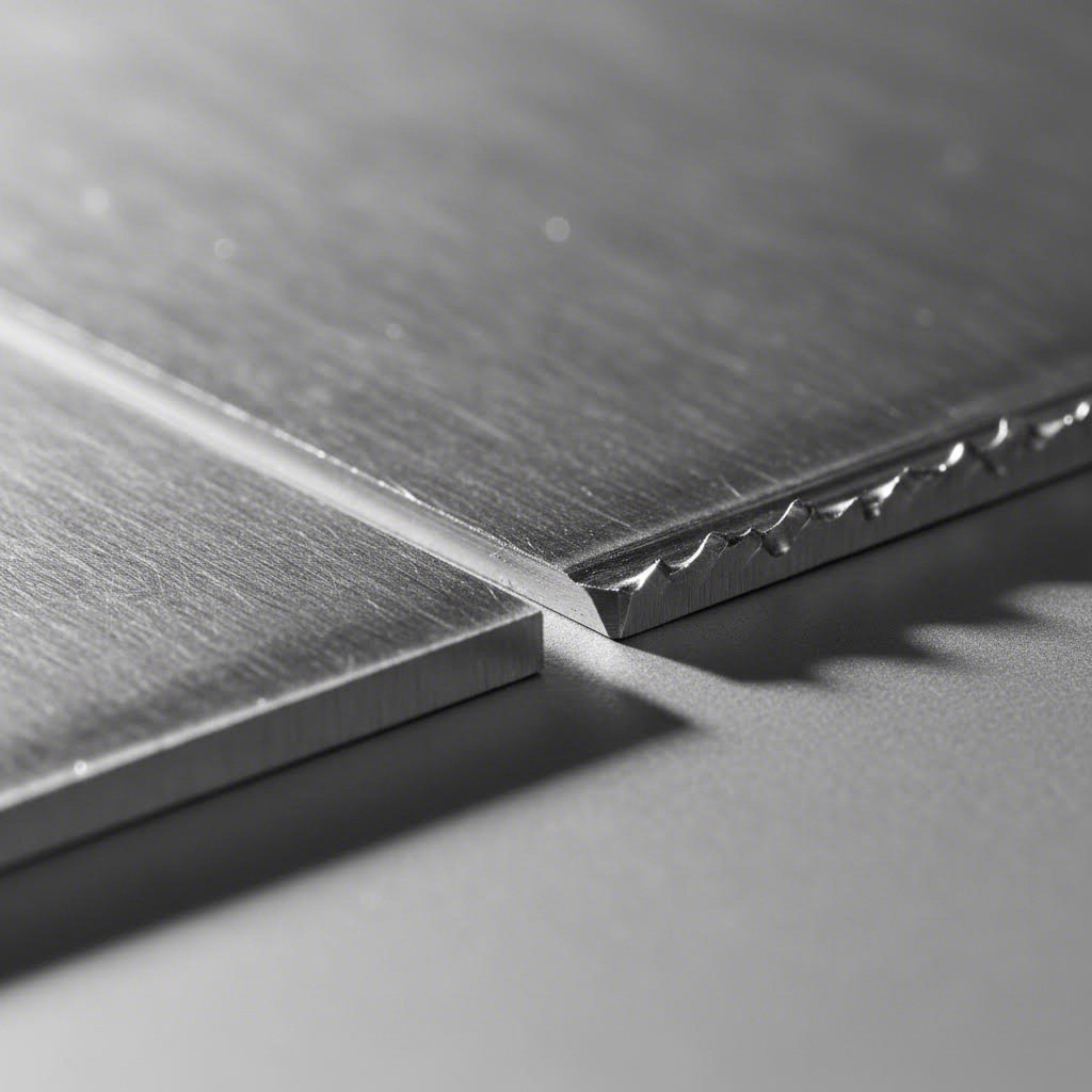
| Edge Quality | Excellent—minimal post-processing | Good—may need deburring | Excellent—smooth finish | Good—depends on tooling |
| Heat-Affected Zone | Small but present | Significant | None | None (mechanical process) |
| Precision Tolerance | ±0.1mm typical | ±0.5mm typical | ±0.1mm typical | ±0.1mm typical |
| Kerf Width | 0.2–0.4mm | 3.8mm+ | 1–1.2mm | Varies by tool diameter |
| Machine Cost | High (~$90,000+) | Low (most affordable) | High (~$195,000+) | Moderate |
| Operating Cost | Low | Low | High | Moderate |
| Cutting Speed (Thin Material) | Very fast | Fast | Moderate | Moderate |
| Cutting Speed (Thick Material) | Moderate | Fast | Slow | Not recommended |
Matching Your Cutting Method to Material Requirements
Here's where many fabricators go wrong: they choose based on what equipment they have rather than what the job actually requires. Services like Send Cut Send have built entire businesses around offering multiple cutting technologies precisely because no single method handles every situation.
Understanding kerf—the material removed by the cutting process—directly impacts your design decisions. A laser cutting operation removes only 0.2 to 0.4mm of material, while plasma cutting takes away 3.8mm or more. When designing mating parts, you must compensate for kerf by adding half the kerf width to inner parts and subtracting half from outer parts. Ignore this, and your assemblies won't fit together properly.
Choose laser cutting when:
- You need intricate details, small holes, or tight tolerances
- Working with thin to medium-gauge materials
- Edge quality matters and you want to minimize secondary finishing
- Production speed on thin sheets is a priority
Choose plasma cutting when:
- Cutting thick conductive metals (steel, aluminum, copper)
- Budget constraints limit equipment investment
- Speed matters more than ultra-fine precision
- Working with structural components where 0.5mm tolerance is acceptable
Choose waterjet cutting when:
- Heat distortion cannot be tolerated
- Material properties must remain unchanged
- Cutting non-conductive or heat-sensitive materials
- Ultra-high precision justifies slower speeds and higher costs
Choose CNC routing when:
- Working with thin aluminum or composite panels
- Cutting corrugated metal or similar materials
- Thermal methods aren't suitable for the material
- Combining cutting with engraving or profiling operations
The bottom line? Match your method to your material and precision requirements first—then factor in cost and speed. Getting this decision right from the start prevents expensive rework and ensures your parts meet specifications every time.
Material Thickness Guidelines and Gauge Specifications
Here's a critical detail most guides overlook: the same cutting method that produces flawless results on thin material might completely fail on thicker stock. Understanding exactly where each technology excels—and where it struggles—saves you from scrapped parts and wasted machine time.
Thickness Limits by Cutting Technology
If you've ever looked at a sheet metal gauge chart, you know that gauge sizes can seem counterintuitive. A lower gauge number actually means thicker material. For reference, 14 gauge steel thickness measures 0.0747 inches (1.897mm), while 11 gauge steel thickness comes in at 0.1196 inches (3.038mm). These measurements matter because each cutting method has an optimal thickness range where it performs best.
What makes this even trickier? Gauge measurements vary between materials. According to industry standard gauge size charts, 14 gauge aluminum sheet measures only 0.06408 inches—noticeably thinner than 14 gauge steel. When ordering stainless steel sheet metal, 14 gauge equals 0.07812 inches. Always verify actual thickness rather than assuming gauge equivalence across different metals.
| Cutting Method | Optimal Thickness Range | Gauge Range (Steel) | Maximum Capability | Quality Sweet Spot |
|---|---|---|---|---|
| Laser Cutting | 0.5mm – 12mm | 28 gauge – 7 gauge | Up to 25mm (carbon steel) | Under 6mm for best edge quality |
| Plasma Cutting | 3mm – 38mm | 11 gauge – thick plate | 50mm+ with high-power systems | 6mm – 25mm for optimal speed/quality |
| Waterjet Cutting | Any thickness | All gauges | Up to 300mm (12 inches aluminum) | Variable—no heat distortion at any thickness |
| CNC Routing | 0.5mm – 6mm | 26 gauge – 10 gauge | ~10mm (soft metals only) | Under 3mm for clean cuts |
Notice something interesting? Waterjet cutting handles the widest thickness range by far—cutting through 12-inch-thick aluminum and up to 9 inches of stainless steel. This versatility comes from the cold-cutting process that doesn't rely on heat to penetrate material.
When to Switch Methods Based on Material Gauge
The relationship between cutting speed, material thickness, and quality outcomes isn't linear. Push any cutting method beyond its optimal range, and you'll see quality degrade rapidly—or speeds drop to impractical levels.
Laser cutting delivers exceptional speed and precision on thin gauge materials. An aluminum sheet in the 18-22 gauge range cuts almost instantaneously with mirror-like edges. However, as thickness increases toward the 7-8 gauge range, cutting speed drops significantly, heat-affected zones expand, and you may notice slight edge taper.
Plasma cutting actually improves in relative quality as material gets thicker. On thin sheets, the heat input creates excessive warping and rough edges. Once you reach 11 gauge steel thickness and beyond, plasma becomes increasingly competitive—delivering fast cuts through material that would slow laser systems considerably.
Waterjet cutting maintains consistent edge quality regardless of thickness since there's no thermal distortion. The tradeoff? Speed decreases significantly as thickness increases. A 1-inch aluminum plate might cut at 2-3 inches per minute compared to 20+ inches per minute on thin sheet stock.
CNC routing should remain your choice only for thin, soft materials. Attempting to route thick stainless steel sheet metal will destroy tooling rapidly and produce unacceptable results.
Here's the practical decision framework:
- Under 3mm (thinner than 11 gauge): Laser cutting typically wins on speed and quality
- 3mm to 12mm (11 gauge to 7 gauge): Laser or plasma depending on precision requirements
- 12mm to 25mm: Plasma for speed, waterjet for precision or heat-sensitive materials
- Over 25mm: Plasma or waterjet—laser becomes impractical
The key insight? Don't force a cutting method beyond its comfortable range just because it's available. Knowing when to switch technologies—or when to outsource to a shop with different capabilities—often determines whether your project succeeds or bleeds money on suboptimal results.
Workholding Techniques for Precision Cutting
You've selected the right cutting method and verified your material thickness—but here's where many projects fall apart. Improper workholding turns precision equipment into expensive scrap generators. A metal sheet that shifts even slightly during cutting produces parts with dimensional errors, rough edges, and wasted material.
Securing Thin Materials Without Distortion
Thin gauge materials present a frustrating paradox: they're lightweight and flexible—exactly the properties that make them difficult to hold securely. Apply too much clamping pressure and you'll distort the workpiece before cutting even begins. Use too little and vibration ruins your edge quality.
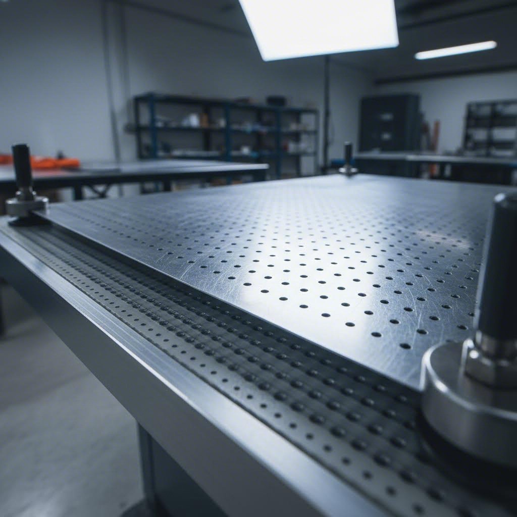
Vacuum tables have emerged as a game-changing solution for thin sheet metal. According to DATRON's engineering research, modern vacuum table designs overcome traditional limitations through permeable substrate systems. These setups use a dense grid of small holes covered by special permeable material that distributes vacuum evenly—allowing you to hold parts too small for conventional vacuum systems.
What makes this approach particularly valuable? You can achieve up to 40% open area while still maintaining secure hold. This means through-cuts and profile operations don't cause vacuum loss—eliminating the need for tabs, screws, or secondary operations to remove finished parts from the sheet.
Sacrificial backing materials serve dual purposes: they prevent cut-through damage to your machine bed while providing additional support to thin workpieces. For laser and plasma operations, aluminum or steel backing plates absorb excess energy. CNC routing benefits from MDF or phenolic backing that allows complete tool penetration without machine damage.
When workpieces aren't perfectly flat—a common reality with thin aluminum sheet metal—thicker permeable substrate materials accommodate slight warping. You can even mill custom pockets or contours into backing material to nest pre-existing parts or handle materials with protruding features.
Workholding Strategies for Different Cutting Methods
Each cutting technology creates unique forces and challenges. Matching your workholding approach to your cutting method prevents the vibration, movement, and distortion that ruin precision work.
Laser cutting workholding benefits from minimal contact approaches since the process generates no mechanical force. Vacuum tables work exceptionally well here. The primary concern is preventing thermal movement as localized heating can cause thin materials to lift or buckle during cutting.
Plasma cutting workholding must account for significant heat input and the magnetic effects of the electrical arc. Heavy-duty clamps positioned away from the cut path prevent movement while allowing thermal expansion. Avoid ferrous fixtures that might interfere with arc stability.
Waterjet workholding requires securing parts against lateral forces from the high-pressure stream. Slat tables with strategically placed clamps are common. For small parts, adhesive tabs or specialized fixturing prevents pieces from falling into the catch tank after cut-out.
CNC routing workholding demands the most robust approach due to substantial lateral cutting forces. Double-sided tape combined with vacuum works for thin stock, while dedicated fixtures with toggle clamps handle heavier operations.
Best practices for aluminum sheet metal:
- Use vacuum tables with tacky permeable substrate for thin gauges
- Avoid excessive clamping pressure that creates stress marks
- Allow thermal expansion room when using thermal cutting methods
- Consider protective film to prevent surface scratching during handling
Best practices for stainless steel sheet:
- Account for higher spring-back compared to mild steel
- Use fixtures that accommodate work hardening characteristics
- Position clamps to prevent movement without inducing residual stress
- Ensure backing materials can handle higher cutting forces
Best practices for galvanized sheet metal:
- Protect zinc coating from clamp damage using soft jaw inserts
- Consider fume extraction requirements when using thermal methods
- Avoid excessive heat that damages the galvanized coating beyond the cut edge
- Use appropriate backing to prevent coating contamination
If your parts will undergo bending after cutting, workholding decisions become even more critical. Residual stresses introduced during improper clamping can cause unexpected spring-back or distortion when parts reach a cnc sheet metal bending machine. According to Smart Sheet Metal's fabrication guide, inefficient tooling, improper clamping, and inadequate support systems exacerbate mechanical stresses that lead to warping during secondary operations.
The consequences of poor workholding extend beyond the cutting operation itself—dimensional inaccuracy, structural weakness, and aesthetic defects all trace back to how securely you held that metal sheet during the initial cut. Investing time in proper workholding setup pays dividends throughout your entire fabrication workflow.
Troubleshooting Common CNC Cutting Problems
Even with the right cutting method and proper workholding, things go wrong. Burrs appear on edges that should be clean. Flat sheets curl into potato chips. Parts come out looking scorched or covered in stubborn residue. These problems don't just affect aesthetics—they cascade into assembly failures, rejected parts, and blown budgets.
According to Frigate's manufacturing research, up to 30% of machined parts require adjustments due to quality issues. Understanding what causes these defects—and how to prevent them—separates efficient operations from shops drowning in rework.
Solving Edge Quality Issues in CNC Cutting
That rough, jagged edge staring back at you? It's telling you something went wrong during the cut. Edge quality problems typically fall into three categories: burrs, dross formation, and surface irregularities.
Burrs are raised metal edges that form when material doesn't separate cleanly during cutting. They're particularly frustrating because they require secondary deburring operations and can cause injury during handling.
Common causes of burrs:
- Worn nozzle or lens on laser systems
- Cutting speed set too high for material thickness
- Beam misalignment or incorrect focus distance
- Inadequate assist gas pressure
Troubleshooting steps for burr elimination:
- Recalibrate your laser cutting machine or CNC tool path
- Inspect lens and nozzle condition—replace if worn
- Reduce feedrate or adjust assist gas settings
- Verify focus distance matches material thickness specifications
So what exactly is dross? To define dross clearly: it's the resolidified molten metal that clings to the underside of cut edges, creating rough protrusions that interfere with part fitment and aesthetics. Unlike burrs that form from incomplete separation, dross results from inadequate ejection of molten material during thermal cutting processes.
Minimizing dross across cutting methods:
- Laser cutting: Increase assist gas pressure and verify nozzle standoff distance
- Plasma cutting: Use elevated cutting supports (slats or grids) to allow dross to fall away cleanly
- Waterjet cutting: Dross isn't typically an issue since the process doesn't melt material
According to JLC CNC's troubleshooting guide, adjusting cutting head standoff distance and boosting assist gas pressure addresses most dross formation issues. When dross persists, the material may simply be too thick for your current parameter settings.
Surface striations and rough finishes indicate problems beyond the cut edge itself:
- Clean optical components (lens, mirrors, collimator) on laser systems
- Use dampers or weighted tables to minimize mechanical vibration
- Tune cutting parameters specifically for your material type and thickness
- Check for gantry looseness or mechanical wear causing instability
Preventing Heat Distortion and Warping
Imagine pulling a freshly cut part from your laser table only to watch it curl like a dried leaf. Heat distortion transforms flat sheet stock into unusable scrap—and it happens more often than most fabricators admit.
Thermal cutting methods (laser and plasma) concentrate intense heat along the cut path. This localized heating creates temperature differentials that cause material expansion in the cut zone while surrounding areas remain cool. The result? Internal stresses that manifest as warping, bowing, or curling.
Factors that increase warping risk:
- Thin gauge stock (more susceptible to thermal effects)
- High cutting power settings
- Slow cutting speeds that allow heat to spread
- Tight corner radii that concentrate heat in small areas
- Insufficient material support during cutting
Prevention strategies:
- Use pulsed laser cutting to minimize continuous heat input
- Increase cutting speed where edge quality permits
- Apply sacrificial backing plates for additional support and heat dissipation
- Consider switching to waterjet cutting for zero-heat edge cuts on heat-sensitive applications
- Design cut sequences that distribute heat across the sheet rather than concentrating it
Heat-affected zones (HAZ) create additional problems beyond visible warping. According to manufacturing quality research, thermal effects can alter material hardness, create microcracks, and induce residual stresses that reduce part longevity. For aerospace and medical applications demanding high thermal stability, these hidden effects matter as much as visible distortion.
When heat distortion cannot be tolerated:
- Switch to waterjet cutting—the cold-cutting process eliminates thermal effects entirely
- Use nitrogen or argon assist gas instead of oxygen to reduce oxidation and heat transfer
- Implement temperature-compensated machining that adjusts parameters based on thermal conditions
When Post-Processing Becomes Necessary
Sometimes, despite your best efforts, cutting alone won't achieve the finish quality your application demands. Knowing when to invest in post-processing—versus chasing diminishing returns on cutting optimization—saves time and money.
Deburring becomes necessary when edge quality requirements exceed what your cutting parameters can deliver. Manual deburring works for small batches, while tumbling or vibratory finishing handles production quantities efficiently.
Anodizing serves dual purposes for aluminum parts: it creates a hard, corrosion-resistant surface while enabling color customization. Parts destined to be anodized benefit from slightly rougher cut edges since the anodizing process itself provides a uniform finish. However, excessive dross or deep striations will telegraph through the anodized surface.
Powder coating offers similar surface enhancement for steel and aluminum parts. Like anodizing, powder coat applications can mask minor surface imperfections—but won't hide significant edge defects. The key insight? Plan your post-processing requirements during the design phase, not as an afterthought when parts don't meet specifications.
Cutting parameters that affect post-processing needs:
- Speed: Faster cuts often produce rougher edges requiring more finishing
- Power: Excessive power creates larger heat-affected zones and more dross
- Gas pressure: Insufficient assist gas leaves more residue requiring cleanup
- Focus position: Incorrect focus degrades edge quality across all parameters
The goal isn't eliminating all post-processing—that's often impractical and expensive. Instead, optimize your cutting parameters to minimize secondary operations while meeting your actual quality requirements. A structural bracket hidden inside an enclosure needs different edge quality than a visible decorative panel.
Cost Analysis for CNC Sheet Metal Cutting
Here's where most fabricators make expensive mistakes: they focus entirely on per-cut pricing while ignoring the factors that actually determine project costs. That bargain cutting method might look attractive until you factor in material waste, secondary finishing, and rejected parts. Understanding true costs separates profitable operations from shops bleeding money on every job.
True Cost Factors Beyond Per-Cut Pricing
When you search for "metal fabrication near me" and request quotes, the numbers you receive rarely tell the complete story. Smart cost analysis requires examining several interconnected factors that compound across your production run.
Machine time represents only the starting point. According to StarLab CNC's industry analysis, a high-powered plasma system cuts 1/2" mild steel at speeds exceeding 100 inches per minute—dramatically faster than waterjet systems operating at 5-20 inches per minute. That speed difference translates directly into machine hours and labor costs.
Material waste often surprises first-time buyers. Remember kerf width differences? Plasma cutting removes 3.8mm or more per cut, while laser takes only 0.2-0.4mm. On a nested sheet with dozens of parts, those millimeters compound into substantial material losses. Services like OSHCut and similar online platforms often provide nesting optimization that minimizes this waste—but the fundamental physics remain.
Secondary processing needs frequently double or triple initial cutting costs:
- Plasma-cut edges typically require deburring or grinding
- Heat-affected zones may need stress relieving for precision applications
- Dross removal adds labor time to every thermal-cut part
- Surface finishing requirements vary by cutting method quality
Tolerance requirements dictate method selection regardless of base cutting costs. If your application demands ±0.1mm precision, plasma cutting's ±0.5mm capability simply won't work—no matter how attractive the price appears.
| Cost Factor | Laser Cutting | Plasma Cutting | Waterjet Cutting |
|---|---|---|---|
| Initial Machine Investment | High (~$90,000+) | Low (most affordable) | High (~$195,000+) |
| Operating Cost Per Hour | Low-Medium | Low | High (abrasive consumption) |
| Cutting Speed (Thin Material) | Fastest | Fast | Slowest |
| Cutting Speed (Thick Material) | Moderate | Fastest | Slow |
| Material Waste (Kerf) | Minimal | Significant | Moderate |
| Secondary Finishing Needs | Minimal | Often required | Minimal |
| Small Batch Cost Efficiency | Good | Excellent | Poor (setup costs) |
| Production Run Cost Efficiency | Excellent | Good | Moderate |
When Premium Cutting Methods Pay for Themselves
Sounds counterintuitive, but sometimes the most expensive cutting method delivers the lowest total project cost. Understanding when premium pays off prevents both over-spending on unnecessary capabilities and under-spending that creates downstream problems.
Laser cutting justifies its higher equipment cost when:
- Edge quality eliminates secondary finishing operations
- Tight tolerances prevent assembly issues and rejected parts
- High production volumes spread equipment costs across thousands of parts
- Complex geometries would require expensive tooling with alternative methods
Waterjet cutting makes economic sense when:
- Heat distortion would require stress relieving or cause rejection
- Material properties must remain unchanged for certification requirements
- Mixed-material cutting eliminates multiple machine setups
- Thick materials would overwhelm laser capabilities
Plasma cutting delivers best value when:
- Material thickness exceeds 6mm and precision requirements allow ±0.5mm
- Speed matters more than edge finish for structural applications
- Budget constraints limit equipment investment
- Parts will undergo welding or coating that masks edge quality
According to Metal Pro Buildings' cost analysis, outsourcing is usually more cost-effective for most businesses, especially when production volumes are low to medium. In-house fabrication requires heavy investment in machines, skilled staff, maintenance, and shop space. Outsourcing lets you pay only for the parts you need while benefiting from vendor expertise and economies of scale.
Here's the practical decision framework for fabrication shops near me searches:
- Under 100 parts annually: Outsource to specialized steel fabrication services
- 100-1,000 parts annually: Evaluate outsourcing versus entry-level equipment
- 1,000+ parts annually: In-house equipment often justifies investment
- Mixed requirements: Consider in-house for common work, outsource specialty cuts
The breakeven calculation depends on your specific situation, but remember: in-house makes sense only when production volumes are high and consistent enough to spread fixed costs over thousands of parts. For most shops, partnering with specialized fabrication services delivers better results at lower total cost than attempting to do everything internally.
Complete Workflow from Design to Finished Parts
Most guides stop at cutting—as if parts magically transform from raw sheet metal into finished components the moment they leave the machine. In reality, the cutting operation represents just one step in a workflow that begins with design decisions and extends through post-processing, inspection, and assembly. Getting any single step wrong cascades into problems downstream.
Design for Manufacturability in Sheet Metal
Before your part ever touches a cutting machine, critical decisions made in CAD determine whether manufacturing goes smoothly or becomes an expensive nightmare. According to Five Flute's DFM guidelines, mechanical engineers should be equipped with a first-principles understanding of sheet metal design for manufacturability—yet most skills are learned on the job rather than in academia.
Software requirements vary based on complexity. Simple 2D profiles can be created in free tools like Inkscape, while complex assemblies demand robust CAD platforms:
- Fusion 360: Cloud-based with real-time collaboration, built-in sheet metal tools, and direct export to cutting services
- SolidWorks: Industry standard with comprehensive sheet metal features and simulation capabilities
- Adobe Illustrator: Suitable for simple decorative cuts at $20.99/month, though it requires training
- Inkscape: Free and cross-platform—ideal for basic profiles and hobbyist work
File formats matter more than many designers realize. DXF (Drawing Interchange Format) remains the universal standard for CNC cutting because it stores vector paths that machines interpret as cutting instructions. According to Xometry's technical documentation, DXF files are open-sourced and compatible with virtually all laser cutting software—unlike proprietary DWG files that may require conversion.
Critical design rules for CNC cutting:
- Hole sizing: Avoid holes with diameters smaller than material thickness—they won't punch or cut cleanly
- Edge distances: Place holes at least 1.5x material thickness from edges and 2x thickness apart from each other
- Bend proximity: Position holes 2.5x thickness plus one bend radius away from bend lines
- Grain direction: Align bend lines perpendicular to material grain direction when possible—failure causes cracking in less ductile metals like 6061-T6 aluminum
- Nesting efficiency: Design parts to nest efficiently on standard sheet sizes, reducing scrap and material costs
When consulting a drill chart for hole specifications, remember that CNC cutting doesn't require standard drill sizes—you can specify any diameter the cutting method supports. However, if parts will receive tapped holes or hardware inserts during secondary operations, designing to standard sizes simplifies downstream processing.
From CAD File to Finished Part
Understanding the complete journey from digital design to physical part helps you anticipate problems before they become expensive mistakes. Here's the step-by-step workflow that professional fabricators follow:
- Create your design in CAD using appropriate sheet metal tools. Configure material thickness, bend radius, and K-factor based on your chosen material. Most CAD platforms include downloadable gauge tables specific to fabrication services.
- Apply DFM checks to verify manufacturability. Check minimum feature sizes, hole-to-edge distances, and bend relief requirements. According to SendCutSend's design guide, features too close together can cause burnout similar to blowing a fuse—the heat or tool pressure overwhelms the material between features.
- Generate flat patterns for bent parts. Your CAD software calculates bend allowance and bend deduction to ensure finished parts match intended dimensions. Improper bend allowances cause tolerance issues for features located across bends.
- Export cutting files in DXF format. Verify that all geometry exports correctly—sometimes complex curves or text require conversion to paths before export. Check that your file contains only the cut geometry, not dimension lines or annotations.
- Submit for quoting and DFM review through your fabrication service. Professional services flag potential issues before cutting begins—holes too close to bends, features that might warp, or geometry that exceeds machine capabilities.
- Review and approve final specifications including material selection, cutting method, and any secondary operations. This is your last opportunity to catch errors before metal gets cut.
- Cutting operation transforms your digital file into physical parts. Machine operators set speed, power, and gas pressure based on material specifications and your tolerance requirements.
- Secondary operations complete the fabrication process. This may include bending, hardware insertion, tapping, deburring, or surface finishing depending on your requirements.
- Final inspection verifies dimensional accuracy and surface quality. For critical applications, this includes tolerance verification against your original specifications.
Tolerances achievable by cutting method:
| Cutting Method | Typical Tolerance | Best-Case Tolerance | Specification Notes |
|---|---|---|---|
| Laser Cutting | ±0.1mm | ±0.05mm | Specify tighter tolerances only on critical features |
| Plasma Cutting | ±0.5mm | ±0.25mm | Not suitable for precision assemblies |
| Waterjet Cutting | ±0.1mm | ±0.05mm | Consistent across thickness range |
| CNC Punch | ±0.1mm | ±0.05mm | Tighter tolerances require closer punch/die fits |
When specifying tolerances in your drawings, call out critical dimensions explicitly rather than applying blanket tolerances to all features. According to Five Flute's guidelines, tolerances should be maximized where possible to reduce cost—tighter tolerances require more expensive tooling and slower processing.
Welding Preparation Considerations
If your parts will be joined through welding, cutting decisions affect weld quality and structural integrity. Understanding the differences between tig vs mig welding helps you specify appropriate edge preparation during the cutting phase.
TIG welding (Tungsten Inert Gas) produces precise, clean welds suitable for thin materials and visible joints. It requires clean, oxide-free edges—meaning parts cut with methods that create significant heat-affected zones may need additional preparation. Aluminum welding particularly benefits from TIG's precision control and reduced heat input.
MIG welding (Metal Inert Gas) handles thicker materials and faster production rates. Edge quality requirements are less stringent since the process deposits more filler material. Parts destined for MIG welding can often skip deburring steps that would be essential for TIG applications.
Edge preparation for welding:
- Laser-cut edges: Generally weld-ready with minimal preparation; small HAZ rarely affects weld quality
- Plasma-cut edges: May require grinding to remove oxidation and dross before welding
- Waterjet edges: Excellent for welding—no heat effects, no oxidation, clean surface
- Beveled edges: Specify during cutting for thick materials requiring full-penetration welds
The tensile strength of welded joints depends partly on base material condition. Heat-affected zones from thermal cutting can alter material properties adjacent to the weld—potentially creating weak points in the final assembly. For structural applications where joint strength is critical, waterjet cutting eliminates this concern entirely.
Planning your complete workflow before cutting begins—from initial CAD design through final assembly—prevents the costly surprises that derail projects and inflate budgets. Each decision cascades forward, making upstream choices critical to downstream success.
Choosing Between DIY and Professional Fabrication
You've mastered the technical knowledge—cutting methods, material specifications, workflow optimization. Now comes the decision that determines whether your project succeeds financially: should you cut in-house or outsource to professional metal fabricators near me? This choice affects everything from capital requirements to quality consistency and delivery timelines.
When to Cut In-House vs Outsource
The DIY versus professional fabrication decision isn't simply about capability—it's fundamentally an economic calculation that many shops get wrong. According to Renew Manufacturing Solutions, deciding between in-house versus outsourced CNC machining comes down to a simple cost-per-job comparison, but examining this mid-project makes it impossible to shift gears economically.
Consider in-house CNC cutting when:
- Production volumes exceed 1,000+ identical parts annually
- You already own appropriate equipment and trained operators
- Rapid iteration requirements demand same-day turnaround
- Proprietary designs require strict confidentiality controls
- Your material and thickness requirements match existing capabilities
Outsourcing makes more sense when:
- Capital investment in equipment cannot be justified by volume
- Projects require cutting technologies you don't own
- Workforce lacks specialized programming and operation skills
- One-time or low-volume projects don't warrant equipment purchases
- Tight deadlines require capacity you cannot provide internally
Here's what many fabricators overlook: the hidden costs of in-house work extend far beyond equipment purchases. According to Metal Works of High Point, investing in CNC machinery demands significant upfront capital investment plus ongoing maintenance costs that compound over time. You must also factor in operator training, software licensing, consumables, floor space, and the opportunity cost of tying up capital in specialized equipment.
When searching for "sheet metal near me" options, you'll discover that outsourcing eliminates equipment maintenance concerns entirely. Professional steel fabricators absorb those overhead costs across hundreds of clients—spreading fixed expenses that would burden a single shop attempting everything in-house.
The technology gap factor: Even well-equipped shops face situations where outsourcing makes sense. If a project requires waterjet cutting but you only own laser equipment, attempting workarounds wastes time and compromises quality. Professional metal fab services maintain multiple cutting technologies precisely because different jobs demand different capabilities.
Evaluating Professional Sheet Metal Services
Not all fabrication services deliver equal quality. Whether you need structural components or decorative custom metal signs, evaluating potential partners against specific criteria prevents costly disappointments.
Critical evaluation criteria for fabrication services:
- Quality certifications: ISO 9001:2015 indicates documented quality management systems. For automotive applications, IATF 16949 certification demonstrates compliance with stringent industry-specific requirements covering everything from process control to traceability
- DFM support: Design for Manufacturability assistance catches problems before cutting begins—saving rework costs and production delays
- Prototyping capabilities: Rapid prototyping services allow design validation before committing to production quantities
- Turnaround time: Quote response speed indicates operational efficiency—partners offering 12-hour quote turnaround demonstrate streamlined processes
- Equipment portfolio: Verify the fabricator maintains appropriate cutting technologies for your material and precision requirements
- Finishing services: In-house powder coating services, anodizing, or other finishing capabilities reduce coordination complexity
- Workforce expertise: According to industry guidance, companies with smaller teams may struggle completing projects on time—verify your partner's capacity matches your volume needs
For automotive and structural applications requiring the highest quality standards, look for partners demonstrating IATF 16949 certification combined with comprehensive capabilities. Shaoyi (Ningbo) Metal Technology exemplifies what to seek in a professional partner: 5-day rapid prototyping, automated mass production capabilities, comprehensive DFM support, and 12-hour quote turnaround—all backed by IATF 16949 certification for chassis, suspension, and structural components.
Questions to ask potential fabrication partners:
- What certifications do you hold, and can you provide current documentation?
- Do you offer DFM review as part of the quoting process?
- What is your typical turnaround for prototypes versus production runs?
- Which cutting technologies do you operate, and what are their precision capabilities?
- Can you handle secondary operations including bending, welding, and finishing?
- What quality inspection processes verify dimensional accuracy?
- How do you handle design changes or engineering revisions mid-project?
When CNC Cutting May Not Be the Best Choice
Here's an honest assessment most cutting guides won't give you: sometimes CNC cutting isn't the optimal solution regardless of whether you do it in-house or outsource.
Consider alternative methods when:
- High-volume simple shapes: Stamping and progressive dies produce parts faster and cheaper for quantities exceeding 10,000 units
- Straight cuts only: Shearing handles straight-line cuts more economically than CNC methods
- Repetitive hole patterns: CNC punching outperforms laser cutting for parts with many similar holes
- Very thick plate: Oxy-fuel cutting handles extremely thick steel more economically than plasma or waterjet
The fabrication method that looks most sophisticated isn't always the most cost-effective. A professional metal fabricator will recommend the appropriate technology for your specific application—even if that means suggesting simpler methods that reduce your costs.
Making the right choice between DIY and professional fabrication requires honest assessment of your capabilities, volumes, and economic constraints. The next section provides a decision checklist to help you evaluate your specific situation systematically.
Making Your CNC Sheet Metal Cutting Decision
You've absorbed a lot of technical information—cutting methods, thickness guidelines, workholding strategies, troubleshooting techniques, and cost analysis frameworks. Now it's time to translate that knowledge into action. The difference between a successful project and an expensive lesson comes down to systematically evaluating your specific requirements before committing resources.
Your CNC Cutting Decision Checklist
Before starting any cnc sheet metal cutting project, work through these decision points. Each factor builds on the others—skip one, and you risk making choices that cascade into problems downstream.
Material and Thickness Assessment:
- Have you verified the exact gauge and material type for your application?
- Does your chosen cutting method perform optimally at your required thickness?
- Will heat-affected zones compromise material properties or cause unacceptable distortion?
- Have you accounted for kerf width in your design dimensions?
Precision and Quality Requirements:
- What tolerances does your application actually require—not wish for, but functionally need?
- Will edge quality from your chosen method meet assembly and aesthetic standards?
- Have you specified critical dimensions separately from general tolerances?
- Do you need certifications or traceability documentation for your parts?
Cost and Volume Considerations:
- Have you calculated total project cost including secondary operations and finishing?
- Does your production volume justify in-house equipment or outsourcing?
- Have you compared quotes from multiple fabrication services?
- Are you optimizing material utilization through efficient nesting?
Workflow and Timeline Planning:
- Have you completed DFM review before finalizing designs?
- Are your CAD files properly formatted (DXF) with clean geometry?
- Have you planned for prototyping before committing to production quantities?
- Does your timeline account for secondary operations like bending or finishing?
Taking the Next Step with Your Project
Knowing when cnc metal cutting serves your needs—and when it doesn't—separates strategic decision-makers from those who waste money on inappropriate methods.
CNC cutting makes sense when:
- Your parts require complex geometries that stamping dies cannot produce economically
- Production quantities fall between prototype and high-volume mass production
- Design iterations demand flexibility without tooling investment
- Precision requirements exceed what manual methods can deliver consistently
Consider alternative methods when:
- Volumes exceed 10,000+ units: Progressive die stamping produces parts faster and cheaper at scale. According to industry analysis, metal shearing is quick and cost-effective for high-volume production settings, especially when straighter cuts are involved
- Simple straight cuts dominate: Shearing handles straight-line cuts more economically than any cnc machine sheet metal approach
- Repetitive hole patterns: CNC punching outperforms laser cutting for metal plate parts with many identical holes
- Budget constraints are severe: Manual methods, while slower, may suit hobbyist or prototype work where precision requirements are modest
For readers working on automotive chassis components, suspension parts, or structural assemblies requiring IATF 16949-certified precision, professional partnerships become essential. Shaoyi (Ningbo) Metal Technology offers what serious fabrication projects demand: 5-day rapid prototyping to validate designs before production commitment, comprehensive DFM support that catches manufacturability issues early, and 12-hour quote turnaround that keeps projects moving. Their automated mass production capabilities bridge the gap between prototype and full-scale manufacturing.
Your immediate action steps:
- Define your minimum acceptable tolerance and edge quality requirements in writing
- Calculate total project cost including all secondary operations—not just cutting
- Request quotes from at least three fabrication services to benchmark pricing
- Submit designs for DFM review before finalizing specifications
- Order prototypes to validate fit and function before production runs
The sheet metal cnc decisions you make today determine whether your project delivers value or drains resources. Armed with the knowledge from this guide—method selection matched to material requirements, realistic cost analysis, proper workflow planning—you're equipped to make choices that succeed. Whether you cut in-house, outsource to local fabricators, or partner with certified manufacturers for precision assemblies, the framework remains the same: match your method to your actual requirements, verify costs comprehensively, and plan your complete workflow before cutting begins.
Frequently Asked Questions About CNC Sheet Metal Cutting
1. Can CNC machines cut sheet metal?
Yes, CNC machines excel at cutting sheet metal using several methods including laser cutting, plasma cutting, waterjet cutting, and CNC routing. Laser cutting is particularly popular for intricate designs, achieving tolerances as tight as ±0.1mm. Plasma handles thicker conductive metals efficiently, while waterjet cutting eliminates heat distortion entirely. Each method suits different material types, thicknesses, and precision requirements. For automotive and structural applications requiring IATF 16949-certified precision, professional manufacturers like Shaoyi Metal Technology offer 5-day rapid prototyping with comprehensive DFM support.
2. How much does CNC cutting usually cost?
CNC cutting costs vary significantly based on method, material, complexity, and volume. Simple parts in small runs typically cost $10-$50 per part, while precision-engineered components may exceed $160 each. Beyond per-cut pricing, consider total project costs including material waste (kerf differences), secondary processing like deburring, and tolerance requirements. Laser cutting has higher equipment costs but lower operating expenses, while plasma offers affordable entry with fast thick-material cutting. Outsourcing often proves more cost-effective for low-to-medium volumes since you avoid equipment investment and maintenance overhead.
3. Is CNC cutting expensive?
CNC cutting can be expensive, but the value lies in precision and repeatability that manual methods cannot achieve. High costs stem from sophisticated machinery, specialized programming, and tight tolerances. However, choosing the appropriate method for your application controls expenses—plasma cutting costs less than laser for thick structural parts where ±0.5mm tolerance is acceptable. Premium methods like waterjet justify higher costs when heat distortion cannot be tolerated. The key is matching method to requirements rather than over-specifying capabilities you don't need.
4. What materials cannot be CNC machined?
Certain materials pose challenges for CNC cutting: rubber and flexible polymers deform under tool pressure, carbon fiber composites create hazardous dust and rapid tool wear, ceramics and glass risk shattering, and extremely soft metals like lead gum up tooling. Foam materials lack rigidity for secure workholding. For sheet metal specifically, most common materials—steel, aluminum, stainless steel, copper, brass—cut successfully with appropriate methods. The limitation is usually matching the cutting technology to material properties rather than absolute incompatibility.
5. What is the best CNC cutting method for thin sheet metal?
Laser cutting typically delivers the best results for thin sheet metal under 3mm (thinner than 11 gauge). It offers exceptional speed, tight tolerances of ±0.1mm, minimal kerf width of 0.2-0.4mm, and excellent edge quality requiring little secondary finishing. For heat-sensitive applications or materials that cannot tolerate any thermal effects, waterjet cutting provides zero heat-affected zones. CNC routing works well for thin aluminum and composite panels. Plasma cutting, while fast, creates excessive heat and rough edges on thin materials, making it better suited for thicker stock above 6mm.