 Small batches, high standards. Our rapid prototyping service makes validation faster and easier —

Custom Machined Parts: From First Sketch To Factory Floor
What Are Custom Machined Parts and Why Do They Matter
Imagine you're designing a specialized robotic arm or a unique automotive component. You search through catalogs, browse supplier websites, and check standard inventory—but nothing fits your exact specifications. Sound familiar? This is precisely where custom machined parts become essential.
Custom machined parts are precision-engineered components manufactured to your exact specifications using Computer Numerical Control (CNC) technology. Unlike off-the-shelf components that come in predetermined sizes and configurations, these parts are created specifically when standard options cannot meet unique design requirements. Through subtractive manufacturing processes, raw materials—whether metals like aluminum and steel, plastics such as Delrin and Nylon, or advanced composites—are transformed into finished components with exceptional accuracy.
At the core of this process, CNC machines follow pre-programmed computer software that guides cutting tools to remove material from a workpiece with extreme precision. As noted by manufacturing experts, this technology produces parts with very tight tolerances, making it ideal for high-end applications in aerospace, engineering, and automobile industries.
How Custom Parts Differ from Standard Components
When you purchase standard components, you're essentially accepting a one-size-fits-many solution. These parts work well for common applications, but they come with inherent limitations. Custom machined parts, on the other hand, flip this approach entirely—your design drives the manufacturing process, not the other way around.
The key characteristics that define precision CNC machining for custom components include:
- Unique Specifications: Every dimension, angle, and feature is tailored to your exact requirements rather than approximated from existing options.
- Tight Tolerances: CNC fabrication achieves accuracy levels that standard parts simply cannot match, often within thousandths of an inch.
- Material Flexibility: You choose the ideal material for your application—from various metals (aluminum, steel, titanium, brass) to engineering plastics (ABS, Nylon, PEEK) and composites.
- Design Freedom: Complex geometries, intricate features, and specialized configurations become possible when you're not constrained by what's already in stock.
The Role of CNC Technology in Custom Manufacturing
So how does CNC technology make all this possible? Think of it as the bridge between your digital design and a physical part. You send your CAD (Computer-Aided Design) file to a machining facility, where it's converted into G-code—the language CNC machines understand. From there, CNC cutting tools move along pre-set coordinates, precisely removing material to shape your component.
Modern CNC metal machining offers incredible versatility. Whether you need CNC milling for complex 3D geometries or CNC turning for cylindrical components, the technology adapts to your requirements. The process is highly automated, which not only ensures consistency from the first part to the thousandth but also reduces the risk of human error.
What makes this approach particularly valuable? Speed and flexibility. Unlike traditional manufacturing that requires expensive molds or dies, CNC machining works directly from digital files. Need to modify your design? Simply update the CAD file and machine a new version. This capability dramatically accelerates product development cycles, allowing you to iterate faster and bring innovations to market sooner.
Essential CNC Machining Processes for Custom Parts
Now that you understand what custom machined parts are, the next question is: how are they actually made? The answer depends largely on your part's geometry, complexity, and production volume. Three primary CNC machining processes dominate custom manufacturing—each with distinct strengths that make it ideal for specific applications. Understanding these differences helps you communicate more effectively with manufacturers and ultimately get better results for your project.
CNC Milling Versus CNC Turning Explained
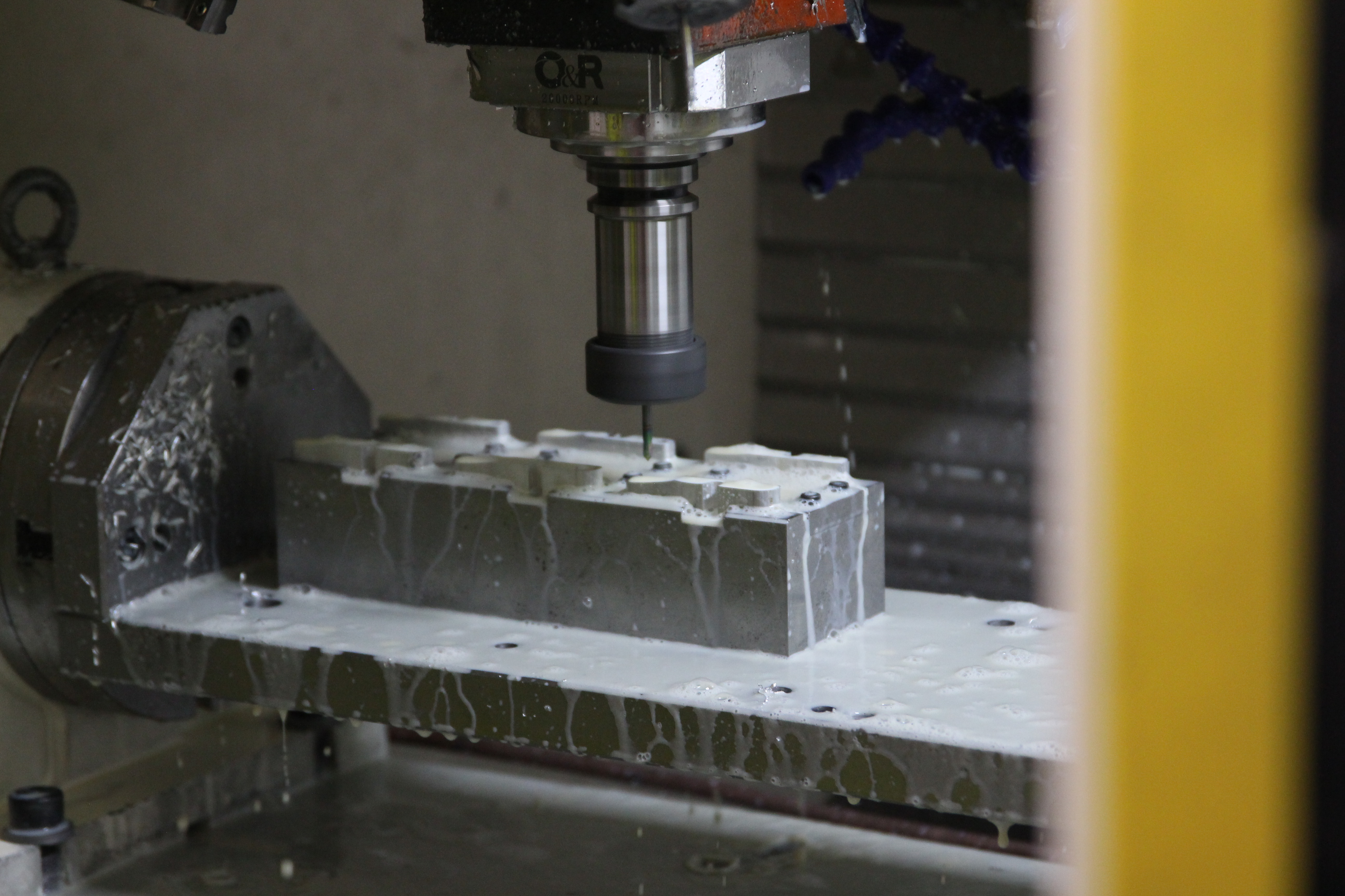
Picture a block of aluminum sitting on a machine table. In CNC machining milling, rotating cutting tools move across this workpiece, removing material to create features like pockets, slots, holes, and complex 3D surfaces. The workpiece typically remains stationary while the tools do the moving. This process excels at producing prismatic shapes—think brackets, housings, plates, and components with intricate surface details.
Milling machines come in different configurations based on their axes of movement:
- 3-Axis Milling: The cutting tool moves along X, Y, and Z axes. Perfect for straightforward parts with features accessible from one direction. Most cost-effective for simpler geometries.
- 4-Axis Milling: Adds rotational movement around one axis, allowing the workpiece to be repositioned during machining. Great for parts requiring features on multiple sides without manual repositioning.
- 5-Axis Milling: The tool or workpiece can move along all three linear axes plus two rotational axes simultaneously. This capability enables machining of highly complex geometries—undercuts, compound angles, and organic shapes—in a single setup. When you need intricate aerospace or medical components, 5 axis cnc machining services deliver unmatched flexibility.
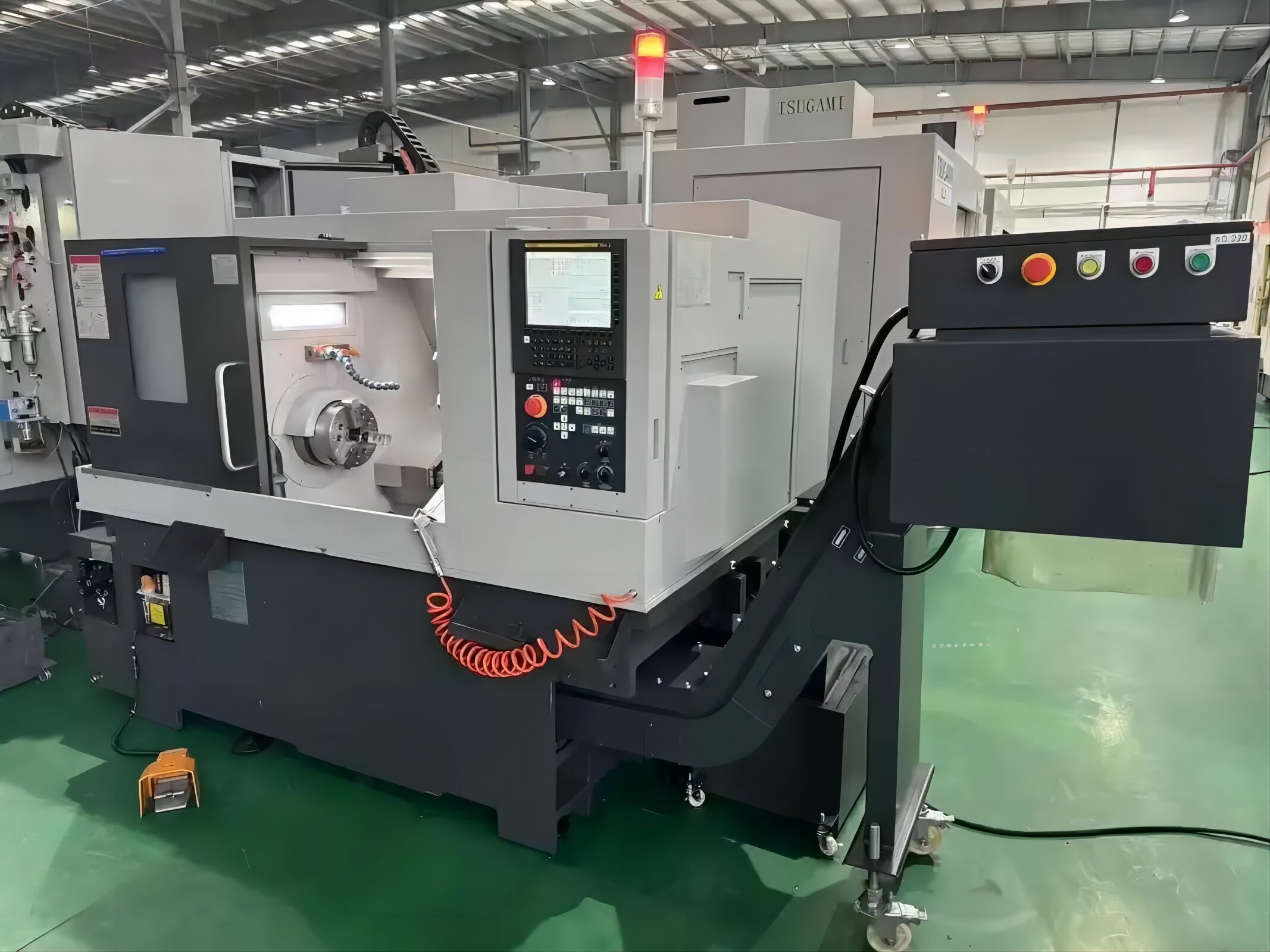
Now imagine a different scenario: you need a shaft, a pin, or any cylindrical component. This is where CNC turning shines. In this process, the workpiece rotates while stationary cutting tools remove material. Think of it like a high-tech pottery wheel, but instead of clay, you're shaping metal or plastic with extreme precision.
CNC turned parts typically include shafts, bushings, fittings, fasteners, and any component that's fundamentally round. The process is incredibly efficient for these geometries because the rotating motion naturally creates smooth, concentric surfaces. When you need a CNC turning service, you're essentially choosing the optimal process for rotationally symmetric components.
When to Choose Swiss Machining for Precision Components
What happens when you need extremely small, slender parts with exceptional precision? Standard turning and milling can struggle here. Enter Swiss machining—a specialized process designed specifically for these challenging applications.
Swiss machining differs fundamentally from conventional turning. In a traditional lathe, the material is held fixed while it spins. In a Swiss lathe, the material not only spins but also moves back and forth through a guide bushing positioned very close to the cutting tools. This design provides continuous support right at the cutting zone, dramatically reducing vibration and deflection.
Why does this matter? According to industry specifications, Swiss machining can typically maintain diametral tolerances of +/- 0.0004 mm on small and flex-vulnerable parts—precision that traditional lathes can only approach through extremely fine cutting and much longer processing times.
Swiss machining excels in specific scenarios:
- Small, High-Precision Parts: Components like connector pins, surgical instruments, and dental implants demand the stability Swiss machines provide.
- Long, Slender Components: Parts with high length-to-diameter ratios that would bend or chatter in conventional turning stay rigid thanks to the guide bushing support.
- Combined Operations: Modern Swiss lathes can perform turning, milling, drilling, and threading simultaneously, reducing cycle times significantly.
- High-Volume Production: Automatic bar feeders keep material flowing continuously, enabling efficient production of thousands of identical components.
However, Swiss machining isn't the right choice for everything. The machines are optimized for smaller workpieces and require specialized programming skills. For larger parts or lower volumes, CNC milling parts or standard turning often prove more economical.
Comparing Your CNC Process Options
Choosing the right process can feel overwhelming, but matching your part's characteristics to the ideal method simplifies the decision considerably. Here's a direct comparison to guide your selection:
| Process Type | Best Applications | Typical Tolerances | Ideal Part Geometry |
|---|---|---|---|
| CNC Milling (3-5 Axis) | Brackets, housings, plates, complex 3D surfaces, prototypes | ±0.025 mm to ±0.005 mm (varies by axis count) | Prismatic shapes, flat surfaces, pockets, intricate contours |
| CNC Turning | Shafts, pins, bushings, fittings, fasteners, cylindrical housings | ±0.025 mm to ±0.010 mm | Rotationally symmetric, cylindrical, conical components |
| Swiss Machining | Medical implants, connector pins, aerospace fasteners, watch components | ±0.005 mm to ±0.0004 mm | Small diameter (typically under 32mm), high aspect ratio, combined turning/milling features |
When evaluating these options, consider your production volume as well. Swiss machining carries higher setup costs but delivers lower per-part costs at high volumes. CNC milling offers the most flexibility for complex geometries and prototyping. Standard CNC turning provides the best economics for cylindrical parts across most volume ranges.
Understanding these processes gives you the foundation to discuss your project intelligently with manufacturers. But process selection is only part of the equation—the material you choose plays an equally critical role in determining your part's performance, cost, and manufacturability.
Material Selection Guide for Custom Machined Components
You've identified the right machining process for your part—but what should it be made from? Material selection is arguably the most consequential decision you'll make for any custom machined parts project. The wrong choice can lead to premature failure, excessive costs, or manufacturing headaches. The right choice balances performance requirements, machinability, and budget constraints to deliver a component that works exactly as intended.
Let's break down your options across two major categories: metals and engineering plastics. Each material brings distinct advantages depending on your application's demands for strength, weight, corrosion resistance, thermal properties, and cost.
Metals for Custom Machined Components
Metals remain the backbone of precision machining, offering combinations of strength, durability, and thermal stability that plastics simply cannot match. However, not all metals machine the same way—or cost the same amount. Understanding these trade-offs helps you specify the optimal material for your application.
Aluminum Alloys dominate custom machining for good reason. They're lightweight (density of just 2.70 g/cm³), machine beautifully, and accept anodizing for enhanced corrosion resistance and aesthetics. Among aluminum options, 6061 aluminum alloy stands out as the workhorse grade. With tensile strength ranging from 124-290 MPa and excellent thermal conductivity of 167 W/m·K, it's ideal for heat sinks, brackets, housings, and structural components where weight savings matter. According to machining property comparisons, aluminum allows cutting speeds of 200-300 m/min with tool lifespans three times longer than stainless steel—translating directly to lower per-part costs.
Stainless Steel enters the picture when corrosion resistance and strength take priority over weight and machinability. 304 stainless steel delivers tensile strength of 515-620 MPa—roughly 2-5 times stronger than 6061 aluminum. It excels in food processing equipment, medical devices, and marine applications where exposure to moisture or chemicals would destroy other materials. The trade-off? Stainless exhibits pronounced work hardening during machining, requiring slower cutting speeds (30-50 m/min) and causing faster tool wear. Expect higher machining costs, but the performance benefits often justify the investment.
Carbon Steel offers an economical alternative when corrosion resistance isn't critical. Grades like 1018 and 1045 machine easily and accept various heat treatments to achieve desired hardness levels. You'll find carbon steel in shafts, pins, fixtures, and industrial machinery components where raw strength matters more than environmental resistance.
Brass and Bronze bring unique advantages for specific applications. Brass machines exceptionally well—often considered the benchmark for machinability—making it cost-effective for complex parts despite higher raw material costs. It's naturally antimicrobial and corrosion-resistant, ideal for plumbing fittings, electrical connectors, and decorative hardware. When machining bronze, you're typically targeting bearing and bushing applications where the material's excellent wear resistance and self-lubricating properties shine. Bronze handles heavy loads and sliding contact far better than most alternatives.
Titanium represents the premium tier—exceptional strength-to-weight ratio, outstanding corrosion resistance, and biocompatibility for medical implants. However, titanium is notoriously difficult to machine. It generates significant heat, requires specialized tooling, and demands experienced operators. Reserve titanium for aerospace, medical, and high-performance applications where its unique properties justify the cost premium.
Engineering Plastics and Their Machining Characteristics
Not every application requires metal. Engineering plastics offer compelling advantages: lighter weight, natural lubricity, electrical insulation, chemical resistance, and often lower machining costs. When you need these properties, plastics deliver performance that metals cannot match.
So, what is Delrin? Delrin is DuPont's trade name for acetal homopolymer (POM-H), a semi-crystalline thermoplastic renowned for its exceptional mechanical properties. This delrin material combines high tensile strength (approximately 13,000 PSI), excellent dimensional stability, and a remarkably low coefficient of friction. According to material specialists, delrin plastic machines extremely well and serves as a metal replacement in gears, bearings, bushings, and structural components across automotive, consumer goods, and industrial applications.
One important distinction: polyacetal delrin (homopolymer) differs from acetal copolymer. While both are polyacetal materials, Delrin offers higher tensile and yield strength, making it better for parts under constant heavy loads. However, it has a porous center that can trap gases or liquids—a consideration for food or medical applications where copolymer acetal might be preferred.
Nylon competes closely with Delrin in many applications. When considering nylon for machining, you're choosing a material with slightly higher tensile strength (12,400-13,500 PSI for extruded and cast versions) and better impact resistance. Nylon absorbs moisture, which can affect dimensional stability in humid environments—something to consider for precision applications. It excels in gears, rollers, wear pads, and components requiring toughness and fatigue resistance.
Polycarbonate stands out for optical clarity combined with impact resistance. If you need transparent components that won't shatter—safety shields, lenses, medical device housings—polycarbonate delivers. It machines cleanly but requires care to avoid stress cracking.
PTFE (Teflon) offers the lowest coefficient of friction of any solid material and exceptional chemical resistance. It handles extreme temperatures and aggressive chemicals that would destroy other plastics. The downside? PTFE is soft and tends to deform under load, limiting its structural applications. It's best suited for seals, gaskets, bearings, and chemical handling equipment.
Material Comparison at a Glance
Choosing between these options requires weighing multiple factors simultaneously. This comparison summarizes the key considerations:
| Material | Key Properties | Common Applications | Machinability Rating |
|---|---|---|---|
| 6061 Aluminum | Lightweight, excellent thermal conductivity, corrosion resistant with anodizing | Heat sinks, brackets, housings, aerospace structures | Excellent |
| 304 Stainless Steel | High strength (515-620 MPa), corrosion resistant, food-safe | Medical devices, food equipment, marine components | Moderate (work hardens) |
| Carbon Steel (1018/1045) | Good strength, heat treatable, economical | Shafts, pins, industrial machinery, fixtures | Good |
| Brass | Excellent machinability, antimicrobial, corrosion resistant | Fittings, electrical connectors, decorative parts | Excellent (benchmark) |
| Bronze | Wear resistant, self-lubricating, handles heavy loads | Bearings, bushings, marine hardware | Good |
| Titanium | Superior strength-to-weight, biocompatible, corrosion resistant | Aerospace, medical implants, high-performance parts | Difficult (requires expertise) |
| Delrin (POM-H) | High strength, low friction, excellent dimensional stability | Gears, bearings, bushings, structural plastic parts | Excellent |
| Nylon | High impact resistance, good wear properties, absorbs moisture | Gears, rollers, wear pads, structural components | Good |
| Polycarbonate | Optical clarity, impact resistant, good dimensional stability | Safety shields, lenses, transparent housings | Good (avoid stress cracking) |
| PTFE | Lowest friction, extreme chemical resistance, wide temperature range | Seals, gaskets, chemical handling, bearings | Good (soft, deforms easily) |
Material selection isn't just about matching properties to requirements—it also affects your project's timeline and budget. Exotic materials like titanium require specialized tooling and slower processing, while readily machinable options like aluminum and brass move through production faster with lower tooling costs. Discuss your performance requirements with your machining partner early; they can often suggest material alternatives that deliver equivalent performance at lower cost.
With your process and material selected, there's one more critical factor that determines whether your parts will function as designed: tolerances and precision specifications.
Tolerances and Precision Standards Explained
You've selected your machining process and chosen the ideal material. But here's a question that trips up many first-time buyers: how precise does your part actually need to be? The answer lies in understanding tolerances—and getting this right can mean the difference between a component that performs flawlessly and one that fails during assembly.
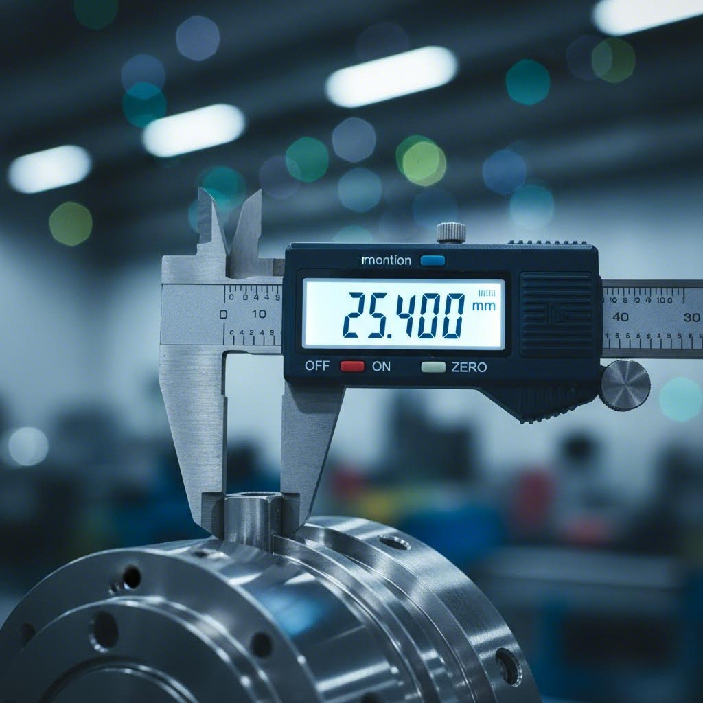
Think of tolerances as the acceptable margin of error in your part's dimensions. No manufacturing process produces absolutely perfect parts. A dimension specified as 10.00 mm might actually measure 9.98 mm or 10.02 mm on the finished component. Tolerances define how much variation you'll accept while still considering the part functional. Specify them too loosely, and your precision machining parts won't fit or perform correctly. Specify them too tightly, and you'll pay significantly more for manufacturing that exceeds your actual needs.
Understanding Tolerance Specifications in CNC Machining
Let's break down what tolerances actually mean in practical terms. When you see a dimension written as 10.00 mm ±0.10 mm, you're looking at a bilateral tolerance—the part can be anywhere from 9.90 mm to 10.10 mm and still be acceptable. That ±0.10 mm represents your tolerance range of 0.20 mm total.
Tolerances come in several forms depending on how they're specified:
- Bilateral Tolerances: Allow variation in both directions (larger and smaller) from the nominal dimension. Most common in general manufacturing.
- Unilateral Tolerances: Permit variation in only one direction. For example, 10.00 mm +0.10/-0.00 means the part can be up to 10.10 mm but never smaller than 10.00 mm.
- Limit Tolerances: Specify upper and lower limits directly without referencing a nominal dimension—for instance, simply stating 9.90 mm to 10.10 mm.
Beyond dimensional tolerances, precision machining services must also control geometric characteristics. This is where Geometric Dimensioning and Tolerancing (GD&T) enters the picture. As explained by manufacturing standards experts, GD&T is a standardized international system using symbols to communicate how parts should fit together and function. It addresses characteristics that simple dimensional tolerances cannot capture—flatness, straightness, perpendicularity, concentricity, and position.
Why does GD&T matter for your CNC machining parts? Imagine a shaft that needs to fit into a bearing. The shaft's diameter might be within tolerance, but if it's slightly bent or tapered, it still won't function correctly. GD&T provides the language to specify these shape requirements precisely, ensuring your parts perform as designed.
How Precision Requirements Impact Your Project
Here's the reality that surprises many buyers: tolerances have an exponential relationship with cost. As noted by industry specialists, achieving tight tolerances requires advanced machinery, high-quality cnc machining materials, and stringent quality control measures—all of which increase production expenses. When tolerances become tighter, costs can rise dramatically rather than linearly.
Understanding tolerance classes helps you specify appropriate precision without overpaying:
| Tolerance Class | Typical Range | Common Applications | Cost Implications |
|---|---|---|---|
| Standard | ±0.125 mm to ±0.25 mm | General mechanical parts, housings, brackets, non-critical components | Baseline cost; achievable with standard equipment and processes |
| Precision | ±0.025 mm to ±0.050 mm | Mating surfaces, bearing fits, assembly interfaces, aerospace components | Moderate premium; requires careful process control and inspection |
| Ultra-Precision | ±0.005 mm to ±0.010 mm | Medical implants, optical equipment, instrumentation, critical assemblies | Significant premium; demands specialized equipment, controlled environments, extensive inspection |
So what is the tolerance for thread holes? This common question deserves a detailed answer because threaded connections require their own tolerance system. The ISO 965-1 standard defines thread tolerance classes that ensure bolts and nuts fit together correctly. According to fastener specifications, the most commonly used classes are 6H for internal threads (nuts) and 6g for external threads (bolts).
These designations work as follows: the number indicates tolerance grade (lower numbers mean tighter tolerances), while the letter indicates position relative to the basic size. Classes 4H/4g through 7H/7g exist for different precision requirements. For most standard assemblies, 6H/6g provides the optimal balance between reliable fit and manufacturing economy. Critical applications might specify 5H/5g for tighter control, while less demanding situations could use 7H/7g to reduce costs.
When specifying thread hole tolerances, remember that manufacturers intentionally make bolts slightly smaller than their nominal size to ensure they'll fit into tapped holes despite normal manufacturing variations. This engineered clearance is what makes threaded assemblies work reliably across different suppliers and manufacturing batches.
The key takeaway? Always specify the loosest tolerances that still meet your functional requirements. Focus tight tolerances only on features critical to fit and function—mating surfaces, bearing bores, and assembly interfaces. For non-critical features, standard tolerances save money without compromising performance. Discuss your application with your precision machining services provider early; they can often recommend where tighter tolerances truly matter and where you're overspecifying.
Now that you understand how tolerances affect both function and cost, let's examine another factor that directly impacts manufacturability: your part's design itself.
Design Guidelines for Optimal Manufacturability
You've selected your process, material, and tolerances—but here's a reality that catches many engineers off guard: the way you design your part can double your manufacturing costs or slash your lead time in half. Every feature you add, every corner you specify, and every hole you place sends ripples through the entire production process. The good news? A few simple design adjustments can dramatically improve outcomes without compromising your part's function.
Design for Manufacturability (DFM) isn't about limiting creativity—it's about understanding how CNC machine parts are actually produced. When you design with the machining process in mind, you're speaking the same language as your manufacturer. The result? Faster quotes, shorter lead times, lower costs, and parts that arrive exactly as you envisioned them.
Critical Design Rules for Machinable Parts
Let's walk through the essential design considerations that separate smooth production runs from expensive headaches. These guidelines apply whether you're designing brackets, housings, or complex assemblies.
Internal Corner Radii
Here's a fundamental fact: CNC cutting tools are round. That means they physically cannot create perfectly sharp internal corners—no matter how clean they look in your CAD model. According to manufacturing specialists, a single sharp corner processed with Electrical Discharge Machining (EDM) can cost three to five times more than a corner machined with a standard end mill.
- Minimum radius: Specify at least 0.005" (0.13mm) for internal corners—but this isn't ideal.
- Recommended radius: Use 0.030" (0.76mm) or larger whenever possible. This allows standard tooling to complete the feature efficiently.
- Deep pockets: Increase radii to 0.060" (1.52mm) or more to reduce tool deflection and improve surface finish.
- Best practice: Choose a radius at least slightly larger than the radius of the cutting tool that will machine the feature.
Wall Thickness Requirements
Thin walls might look elegant in your design, but they create real problems during machining. When walls become too thin, they flex under cutting pressure, causing chatter, poor surface finish, and dimensional inaccuracies. As DFM experts note, walls thinner than 0.5mm can increase machining time by 100% to 300% because the machinist must take extremely light, careful cuts.
- Aluminum minimum: 0.8mm (walls thinner than this are over 50% more likely to deform)
- Steel minimum: 0.5mm (stronger material allows thinner walls)
- Plastics minimum: 1.5mm (lower stiffness requires thicker sections)
- Recommended approach: Design for 1.5mm or greater whenever structural requirements allow
Hole Depth-to-Diameter Ratios
Deep, narrow holes challenge standard tooling. A hole's aspect ratio—depth divided by diameter—determines which tools and techniques your manufacturer must use.
- Standard drilling: Up to 4:1 aspect ratio works efficiently with standard drill bits
- Peck drilling required: Ratios above 4:1 need peck drilling cycles (drill partially, retract, repeat) to clear chips—adding 20-40% to cycle time
- Specialized tooling: Ratios exceeding 10:1 may require gun drills or specialized deep-hole techniques, significantly increasing cost
- Design alternative: Consider whether deep holes can become through-holes or be accessed from both sides
Thread Specifications
Threaded holes require attention to both the thread itself and the surrounding geometry. When specifying NPT (National Pipe Thread) connections, proper dimensions ensure reliable seals. For example, 3/8 NPT thread dimensions specify 18 threads per inch with a tap drill size of 37/64" (0.578"). Similarly, when determining 1 4 NPT hole size requirements, you'll need a tap drill of 7/16" (0.438") for the 1/4"-18 NPT standard.
- Pre-drill depth: Always specify drilling depths deeper than tapping depths to accommodate tap lead-in (2-3 threads for forming taps, 5-7 threads for cutting taps)
- Wall clearance: Keep tapped holes away from pocket walls to prevent breakthrough—use smaller thread sizes if space is limited
- Through-holes preferred: When possible, design through holes for a 4 M bolt or any threaded fastener rather than blind holes—this reduces machining time and eliminates chip evacuation concerns
- Thread class specification: Specify thread class (like 6H/6g) rather than dictating specific drill sizes—this gives manufacturers flexibility to optimize their process
Avoiding Common Design Mistakes That Increase Costs
Beyond individual feature guidelines, certain design patterns consistently drive up costs without adding functional value. Recognizing these pitfalls helps you make smarter trade-offs.
Knife Edges and Sharp Exterior Corners
Where two surfaces meet at acute angles, fragile "knife edges" form. These features cause problems during machining (tool chatter, burr formation) and throughout the part's life (handling damage, stress concentration). The solution? Add small fillets of 0.005"-0.015" (0.13-0.38mm) to exterior corners. Manufacturing teams typically add these anyway—specifying them upfront eliminates guesswork.
Unnecessary Geometric Complexity
Complex curves and varying radii might look impressive in CAD, but they create significant manufacturing overhead. According to DFM analysis, complex curves can increase programming time by 100-300% and machining time by 200-400% compared to simple, consistent geometry. Before finalizing any decorative feature, ask: does this curve serve a functional purpose, or is it purely aesthetic? Every CNC cut along a complex path takes time—and time directly translates to cost.
Features Requiring Five-Axis Machining
Parts with features oriented at compound angles or requiring undercuts often demand five-axis machining—costing 300-600% more than equivalent three-axis operations. Where possible:
- Align features with X, Y, and Z axes
- Avoid undercuts that require special tooling or secondary operations
- Break complex parts into simpler subassemblies when geometry absolutely requires difficult orientations
Cast-to-Machined Design Translation
Designing a prototype for CNC machining using a casting-optimized CAD model creates unnecessary complications. Draft angles essential for casting become manufacturing headaches when CNC cuts must follow tapered surfaces. Create separate design versions: one optimized for eventual casting production, another simplified for machined prototypes with parallel walls and consistent features.
The choices made during the design phase ripple through every subsequent manufacturing step. A seemingly minor design decision—like specifying an unnecessary fillet or choosing an overly tight tolerance—can transform a straightforward CNC machining operation into a complex, time-intensive process that delays product launch by weeks.
Effective DFM implementation can reduce manufacturing costs by 15-40% and cut lead times by 25-60% compared to non-optimized designs. That's not a minor improvement—it's the difference between meeting your launch date and scrambling to explain delays. With your design optimized for manufacturability, you're ready to understand how the entire production process unfolds from your CAD file to finished parts.
The Custom Machining Process from Prototype to Production
You've designed your part with manufacturability in mind—but what actually happens after you upload that CAD file? For many engineers and procurement teams, the journey from digital design to physical component feels like a black box. You submit files, wait, and eventually parts arrive. But understanding what occurs inside that process gives you real power: the ability to set realistic timelines, avoid costly surprises, and communicate effectively with your manufacturing partner.
The truth is, CNC prototyping through production scaling involves distinct phases, each with unique considerations. A single prototype demands different thinking than a run of fifty parts, which differs entirely from manufacturing thousands. Let's demystify this journey step by step.
From CAD File to Finished Part
Every custom machined part begins its physical life as a digital model—but the path from that file to a finished component involves more steps than many realize. According to manufacturing process experts, the CNC machining process consists of several key stages, each essential for ensuring parts meet exact design specifications.
Here's the typical workflow from quote request to delivered parts:
- CAD File Submission and Initial Review: You upload your 3D model (typically STEP, IGES, or native CAD formats) along with drawings specifying critical dimensions, tolerances, and surface finish requirements. The manufacturer's engineering team reviews files for completeness and identifies any immediate concerns—missing dimensions, unclear specifications, or potential manufacturability issues.
- Design for Manufacturability (DFM) Feedback: Experienced manufacturers don't just quote your design—they improve it. This stage identifies features that may cause problems: wall sections too thin for stable machining, radii too small for standard tooling, or tolerances tighter than functionally necessary. You'll receive recommendations that can reduce costs and improve outcomes without compromising your design intent.
- Material Selection Confirmation: While you may specify a material, this stage confirms availability and suitability. If your requested alloy has extended lead times, alternatives with equivalent properties might be suggested. The manufacturer also verifies that material certifications can meet your requirements—critical for aerospace, medical, or automotive applications.
- Process Planning and Programming: With design and material confirmed, manufacturing engineers determine the optimal machining strategy. This includes fixture design (how the part will be held), tool selection, cutting parameters, and operation sequencing. For CNC prototype machining, this planning must balance speed against precision—rapid turnaround matters, but not at the expense of part quality.
- Production and In-Process Inspection: The actual machining begins. Depending on part complexity, this might involve multiple setups, tool changes, and intermediate inspections. Quality checks during production catch issues before they propagate through an entire batch.
- Final Inspection and Finishing: Completed parts undergo thorough dimensional verification against your specifications. Secondary operations like deburring, anodizing, or other surface treatments happen at this stage. Inspection reports documenting actual measurements accompany delivery for critical components.
- Packaging and Delivery: Proper packaging prevents damage in transit—especially important for precision surfaces or delicate features. Parts ship with required documentation: certificates of conformance, material certifications, and inspection data as specified.
This process applies whether you're ordering one prototype or one thousand production parts—but the emphasis shifts significantly depending on quantity.
Scaling from Prototype to Production
Imagine you're developing a new product. Your first need is simple: get a physical part in hand to verify your design works. Later, you'll need dozens for testing and qualification. Eventually, you'll require hundreds or thousands for market launch. Each phase carries different priorities and challenges.
Prototype Quantities (1-10 Parts)
At this stage, speed and flexibility trump everything else. You're validating concepts, testing fits, and likely iterating rapidly. Prototype machining services understand this urgency—many offer expedited turnarounds of one to three days for straightforward parts.
What matters during prototyping:
- Turnaround time: Days, not weeks. Every day of delay extends your development timeline.
- Design flexibility: You'll probably change something. Prototype machining services providers should accommodate revisions without lengthy requoting processes.
- Material approximation: Using readily available materials that approximate final production materials often makes sense when validating form and fit.
- Cost per part: Higher than production—setup and programming costs spread across very few parts. This is expected and acceptable.
According to manufacturing transition experts, the prototype stage is invaluable because it "helps identify design flaws, test the functionality, and gather user feedback, which are vital for refining the product." Rapid CNC prototyping lets you fail fast and learn faster—ultimately accelerating your path to a production-ready design.
Low-Volume Production (10-100 Parts)
You've validated your design. Now you need enough parts for extensive testing, customer samples, or initial market entry. This bridge stage introduces new considerations that CNC machining prototyping alone doesn't address.
What changes at low volume:
- Process consistency: One perfect prototype doesn't guarantee fifty identical parts. Statistical process control and documented procedures become important.
- Final materials: Using actual production materials matters now—your testing must reflect real-world performance.
- Design freeze: Changes become more expensive. Ideally, your design is stable before committing to low-volume runs.
- Quality documentation: First article inspection reports, material certifications, and process validation may be required.
- Cost optimization: Setup costs now spread across more parts, reducing per-piece pricing. Programming and fixturing investments start paying dividends.
As one manufacturing expert notes, low-volume production "allows for further testing, market evaluation, and refinement of the product and production process without the significant cost and commitment of large-scale manufacturing." Companies can "quickly iterate on production designs, adapt to industry changes or introduce new features based on immediate feedback."
High-Volume Manufacturing (100+ Parts)
Production scale changes everything. The focus shifts from speed and flexibility to efficiency, consistency, and cost optimization. Setup and programming—significant costs for prototypes—become negligible when spread across hundreds or thousands of parts.
What matters at production volume:
- Process efficiency: Cycle time optimization becomes critical. Shaving seconds off each part translates to significant savings across large quantities.
- Tool life management: Cutting tools wear out. Predictable replacement schedules prevent quality degradation during long production runs.
- Supply chain reliability: Material availability and consistent supply matter when production schedules depend on continuous flow.
- Statistical quality control: Sampling plans and SPC charts replace 100% inspection for most features.
- Scalability: Can your supplier double output if demand spikes? Understanding capacity constraints prevents supply disruptions.
Lead Time Expectations and Influencing Factors
One of the most common questions in custom machining: how long will this take? The honest answer depends on multiple variables, but understanding what drives lead times helps you plan realistically.
| Production Stage | Typical Lead Time | Key Factors Affecting Timeline |
|---|---|---|
| CNC Prototype (1-5 parts) | 1-5 business days | Part complexity, material availability, tolerance requirements |
| Low-Volume (10-100 parts) | 1-3 weeks | Fixture requirements, inspection documentation, secondary operations |
| Production Volume (100+ parts) | 2-6 weeks | Material procurement, capacity scheduling, quality requirements, certifications |
Several factors consistently impact lead times regardless of quantity:
- Material availability: Common aluminum and steel grades ship quickly. Exotic alloys or specific tempers may require weeks of procurement time.
- Part complexity: A simple bracket machines faster than a multi-feature housing requiring multiple setups and extensive 5-axis work.
- Tolerance demands: Tighter tolerances require slower machining, additional inspection, and potentially secondary finishing operations.
- Secondary operations: Heat treatment, anodizing, plating, or other finishing processes add days to the timeline.
- Documentation requirements: First article inspections, material certifications, and extensive quality documentation take time to prepare.
- Design completeness: Incomplete drawings or ambiguous specifications trigger RFI cycles that delay quoting and production start.
The journey from prototype to mass production is multifaceted and challenging, yet crucial for the successful scaling of a product. Each stage—prototype, low volume, and mass production—presents unique challenges and requirements.
Understanding this progression helps you set appropriate expectations and communicate effectively with manufacturing partners. A supplier promising three-day delivery on a complex, tight-tolerance production run either doesn't understand the work or isn't being honest about capabilities. Conversely, a simple CNC prototype shouldn't require three weeks unless material procurement poses genuine challenges.
With this production journey understood, you're ready to explore how requirements vary across different industries—and why the standards for aerospace components differ dramatically from consumer products.
Industry Applications and Specialized Requirements
A bracket destined for a commercial aircraft lives a fundamentally different life than one inside a consumer appliance. The temperatures, pressures, vibrations, and consequences of failure couldn't be more distinct—and these differences drive dramatically different manufacturing requirements. Understanding how custom machined parts serve various industries helps you communicate your needs more effectively and evaluate whether a potential supplier truly understands your application.
Each industry has developed its own ecosystem of standards, certifications, and specifications. What qualifies as acceptable in industrial machinery might fail catastrophically in aerospace. What works for consumer products could never meet medical device regulations. Let's explore what makes each sector unique—and what you should expect from a machining partner serving your industry.
Aerospace and Defense Machining Requirements
When it comes to CNC machining aerospace components, the stakes couldn't be higher. Modern aircraft contain between 2 and 3 million precision-machined parts, each requiring rigorous quality control. According to aerospace machining specialists, the global aerospace industry depends on specialized manufacturing techniques to maintain its exceptional safety record of just 0.2 fatal accidents per million flights.
What separates aerospace cnc machining from standard manufacturing? The answer lies in every aspect of the process:
- Extreme Tolerances: While standard machine shops typically work with tolerances of ±0.005 inches, aerospace precision machining consistently achieves ±0.0001 inches or better. This ten-fold improvement in precision requires specialized equipment, environmental controls, and operator expertise.
- Demanding Operating Conditions: Components must perform in environments not encountered elsewhere—temperatures reaching 2000°F (1093°C) in jet engines, pressure variations from 0.2 to 1.2 atm during flight, and temperature swings from -65°F to +350°F (-54°C to +177°C) according to Boeing's engineering standards.
- Exotic Materials: Machining titanium becomes routine in aerospace applications. This metal weighs 40% less than steel while offering comparable strength, making it ideal where weight reduction is crucial. Superalloys like Inconel, Hastelloy, and Waspaloy withstand extreme heat in mission-critical applications where other materials would fail.
- Weight Optimization: Research by Airbus Engineering shows that a 100-pound weight reduction in a commercial airliner saves approximately 14,000 gallons of fuel annually. Every gram matters, driving complex pocket designs that remove material while maintaining structural integrity.
The certification that matters most in aerospace? AS9100. This quality management system represents the global standard specifically developed for aerospace manufacturing, adding 105 specific requirements beyond the basic ISO 9001:2015 framework. Facilities must pass rigorous third-party audits to obtain and maintain certification, with recertification required every three years.
Medical Device Component Standards
Medical machining presents a unique combination of challenges: precision comparable to aerospace, materials that must interact safely with human tissue, and regulatory oversight that traces every component from raw material to patient.
The requirements for medical device machining include:
- Biocompatibility: Materials must be tested to ensure they won't cause adverse reactions when in contact with blood, tissue, or bodily fluids. Titanium's biocompatibility makes it essential for implants, while specialized stainless steel grades serve surgical instruments.
- Sterilization Compatibility: Components must withstand repeated sterilization cycles—autoclaving, gamma radiation, ethylene oxide, or other methods—without degrading. Material selection and surface finish directly impact sterilization effectiveness.
- Surface Finish Requirements: Microscopic imperfections can harbor bacteria or cause tissue irritation. Medical components often require surface roughness values of 4-8 μin Ra for bearing surfaces—levels demanding specialized finishing processes.
- Full Traceability: Every component must trace back to specific material lots, machining dates, operators, and inspection records. This documentation chain enables rapid response if any quality concern emerges.
The governing standard for medical device manufacturers is ISO 13485. As explained by compliance specialists, meeting ISO 13485 is crucial for establishing a quality management system specifically for medical devices. It helps ensure consistent design, development, production, and delivery of safe, effective products while facilitating regulatory approvals in many countries.
Beyond ISO 13485, FDA compliance requirements add another layer for U.S. market access. Regulations including 21 CFR Part 820 (Quality System Regulation) and 21 CFR Part 11 (electronic records and signatures) impose specific documentation and process control requirements that manufacturers must embed into their operations.
Automotive Industry Expectations
Automotive manufacturing operates at the intersection of precision and volume. A single vehicle model might require millions of identical components over its production life—each one meeting exactly the same specifications as the first.
The automotive sector's unique demands include:
- High-Volume Capability: Unlike aerospace's small batches of complex parts, automotive often requires tens of thousands of identical components with rapid delivery schedules. Suppliers must demonstrate capacity to scale without sacrificing quality.
- Statistical Process Control: With volumes too high for 100% inspection, automotive relies heavily on SPC to monitor and control production. Suppliers must implement and document statistical methods proving their processes remain stable.
- Supply Chain Integration: Just-in-time delivery expectations mean suppliers become extensions of assembly lines. Delivery reliability matters as much as part quality—a missing shipment can halt entire production facilities.
- Cost Optimization: Competitive pricing pressure is intense. Automotive suppliers must continuously improve efficiency while maintaining quality standards.
The certification standard defining automotive quality expectations is IATF 16949:2016. According to the Automotive Industry Action Group, this standard defines quality management system requirements for organizations across the global automotive industry. Developed with unprecedented industry engagement, it effectively replaced ISO/TS 16949 and harmonizes assessment and certification systems across the international automotive supply chain.
IATF 16949 goes beyond general quality management to address automotive-specific concerns: Advanced Product Quality Planning (APQP), Failure Mode and Effects Analysis (FMEA), Production Part Approval Process (PPAP), Measurement System Analysis (MSA), and Statistical Process Control (SPC). These "Core Tools" form the foundation of automotive quality methodology.
Industry Requirements Comparison
Comparing requirements across industries reveals both commonalities and critical differences. Use this comparison to understand what your application truly demands:
| Industry | Typical Materials | Critical Specifications | Key Certifications |
|---|---|---|---|
| Aerospace & Defense | Titanium alloys, Inconel, aluminum 7075, stainless steel, superalloys | Tolerances to ±0.0001", extreme temperature performance, weight optimization, full traceability | AS9100, NADCAP (for special processes) |
| Medical Devices | Titanium (biocompatible), 316L stainless steel, PEEK, cobalt-chrome | Biocompatibility, sterilization compatibility, surface finish Ra 4-8 μin, complete documentation | ISO 13485, FDA 21 CFR Part 820, ISO 14971 (risk management) |
| Automotive | Aluminum alloys, carbon steel, stainless steel, engineering plastics | High-volume consistency, SPC capability, JIT delivery, cost efficiency | IATF 16949:2016, customer-specific requirements |
| Industrial/General | Carbon steel, aluminum, brass, bronze, standard plastics | Functional fit, reasonable tolerances, value engineering, standard lead times | ISO 9001:2015 (baseline) |
Notice how material choices reflect application demands. Aerospace prioritizes strength-to-weight ratio, driving titanium and aluminum alloy adoption. Medical applications require proven biocompatibility. Automotive balances performance against cost at volume. Industrial applications typically accept wider material options based on functional requirements.
Similarly, certification requirements correlate directly with consequence severity. Aerospace component failure can be catastrophic and irreversible. Medical device failures affect patient safety. Automotive failures trigger costly recalls and safety concerns. Industrial equipment failures, while serious, generally present lower immediate risk to life—reflected in less stringent baseline certification requirements.
When selecting a machining partner, verify their certifications match your industry's requirements. An ISO 9001-certified shop may produce excellent general industrial components but lack the documentation systems, process controls, and inspection capabilities that aerospace or medical applications demand. Conversely, paying for AS9100-level processes makes little sense for non-critical industrial parts where ISO 9001 provides appropriate quality assurance.
Understanding these industry-specific requirements prepares you for the next crucial decision: choosing the right manufacturing partner to produce your custom machined parts.
Choosing the Right Custom Machining Partner
You've designed your part, selected materials, specified tolerances, and understand your industry's requirements. Now comes a decision that can make or break your entire project: choosing which manufacturer will actually produce your custom machined parts. Search "CNC machine shops near me" or "machining shops near me" and you'll find dozens of options—but how do you separate genuinely capable partners from shops that will deliver headaches instead of precision components?
The difference between a good machining partner and the wrong one extends far beyond price. It affects your lead times, quality consistency, communication experience, and ultimately your product's success. According to manufacturing selection experts, it's not just about getting a part made—it's about getting a perfect part made, efficiently and reliably. Let's examine the criteria that actually matter when evaluating precision machining companies.
Quality Certifications That Matter
Certifications serve as shorthand for capability. They indicate that a manufacturer has invested in documented systems, undergone independent audits, and committed to specific quality standards. But not all certifications carry equal weight—what matters depends entirely on your industry.
Here's what to look for based on your application:
- ISO 9001:2015: The baseline quality management certification. Any serious manufacturing operation should hold this as a minimum. It demonstrates systematic approaches to quality across operations but doesn't address industry-specific requirements.
- IATF 16949:2016: The automotive industry standard. If you're sourcing components for vehicles or automotive systems, this certification is essentially mandatory. It encompasses ISO 9001 requirements plus automotive-specific elements including Advanced Product Quality Planning (APQP), Production Part Approval Process (PPAP), and Statistical Process Control (SPC).
- AS9100: The aerospace and defense standard. This certification adds 105 requirements beyond ISO 9001, addressing the extreme precision, traceability, and documentation aerospace applications demand.
- ISO 13485: The medical device standard. Essential for components destined for medical applications, it ensures quality systems specifically designed for safe, effective medical devices.
When searching for local machine shops or a CNC machine shop near me, don't assume certifications—verify them. Ask for certificate copies and check validity dates. Certifications require ongoing surveillance audits; an expired certificate suggests systemic problems.
Evaluating Manufacturing Capabilities
Certifications indicate quality systems, but equipment and expertise determine what a shop can actually produce. Your evaluation should examine multiple capability dimensions:
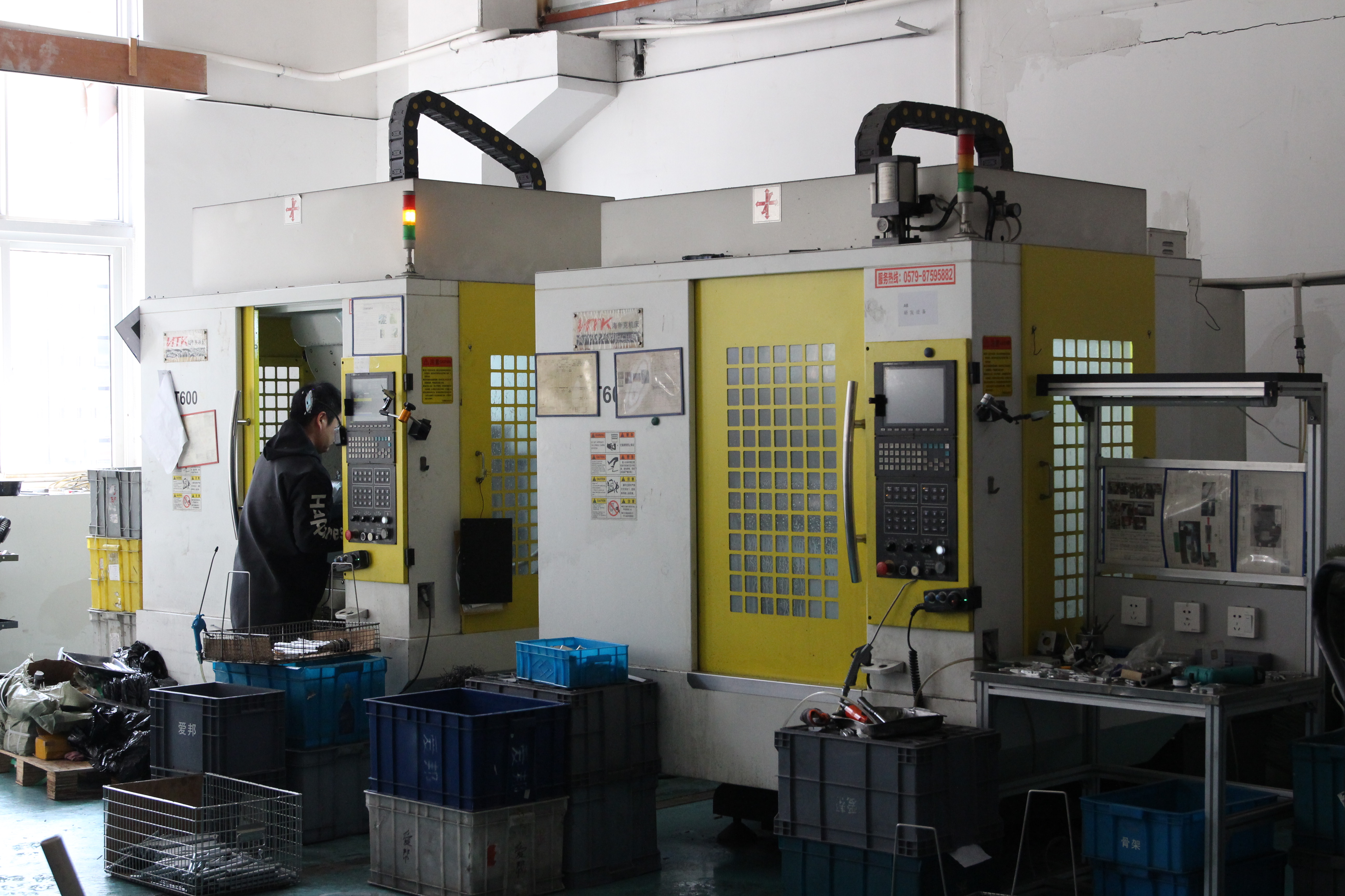
Equipment and Technology
What machines does the facility operate? As noted by CNC manufacturing specialists, the quality of output is inextricably linked to the quality and capability of equipment. A modern, well-maintained fleet of machines signals forward-thinking and reliable operations.
- Machine types: Do they have the specific capabilities your parts require—3-axis, 4-axis, or 5-axis milling? CNC turning? Swiss machining for small precision components?
- Inspection equipment: Look for Coordinate Measuring Machines (CMMs), optical comparators, surface roughness testers, and other verification tools. According to industry experts, a shop with advanced, regularly calibrated inspection tools demonstrates commitment to accuracy.
- Maintenance protocols: Even the best machines are only as good as their maintenance. Reputable shops maintain rigorous maintenance schedules and calibration procedures ensuring equipment consistently performs at peak capability.
Quality Control Processes
Beyond certifications and equipment, how does the shop actually control quality during production? Statistical Process Control (SPC) represents the gold standard for process monitoring. As defined by the American Society for Quality, SPC uses statistical techniques to control processes and discover issues in internal systems before they result in defective parts.
Key quality control indicators include:
- In-process inspection: Does the shop catch errors during production rather than only performing final checks? Proactive quality control minimizes waste and ensures consistent output.
- First Article Inspection (FAI): For production runs, FAI verifies initial parts meet all specifications before full production proceeds.
- Statistical Process Control: SPC charts and capability studies demonstrate process stability—particularly important for higher volumes where 100% inspection becomes impractical.
- Traceability systems: Can they provide complete documentation tracking materials and processes? This capability is vital for critical components, allowing you to trace each part's journey from raw material to finished product.
Material Expertise
Different materials machine differently. A shop experienced with aluminum may struggle with titanium's demanding characteristics. Verify the manufacturer has documented experience with your specific materials—ask for examples of similar work and references from comparable projects.
Communication and Responsiveness
Machining is a collaborative process. How quickly does the shop respond to inquiries? Do they provide clear, detailed quotes? Can you communicate directly with technical staff when needed? As manufacturing experts emphasize, excellent communication and project management skills can make or break a project. Clear, consistent communication helps manage expectations and resolves issues swiftly.
Lead Time Reliability and Scalability
When you need parts, timing matters as much as quality. Evaluate potential partners on their ability to meet—and consistently hit—delivery commitments.
- Prototype turnaround: Can they deliver rapid prototypes when you need fast design validation? Some precision machining companies offer expedited services with lead times as short as one working day for urgent needs.
- Production capacity: If your project succeeds, can they scale from prototypes to production volumes without quality degradation or delivery delays?
- On-time delivery track record: Ask about their delivery performance metrics. Reliable partners track and report their on-time delivery rates.
The ability to scale seamlessly from rapid prototyping to mass production represents a significant advantage. Working with a single partner across your product lifecycle eliminates supplier transitions, preserves institutional knowledge about your parts, and simplifies supply chain management.
Putting Evaluation Criteria into Practice
When searching for a machinist near me or evaluating precision machining companies, consider creating a structured evaluation framework. Here's a practical checklist:
- Verify certifications: Request current certificates matching your industry requirements (ISO 9001 minimum; IATF 16949, AS9100, or ISO 13485 for regulated industries)
- Assess equipment: Confirm they have appropriate machinery for your part geometry and tolerance requirements
- Review quality systems: Ask about SPC implementation, inspection capabilities, and traceability documentation
- Check material experience: Verify demonstrated expertise with your specific materials
- Evaluate communication: Note response times and quote clarity during initial interactions
- Confirm capacity: Ensure they can handle your volumes—both current prototypes and potential production scaling
- Request references: Ask for contacts at companies with similar applications
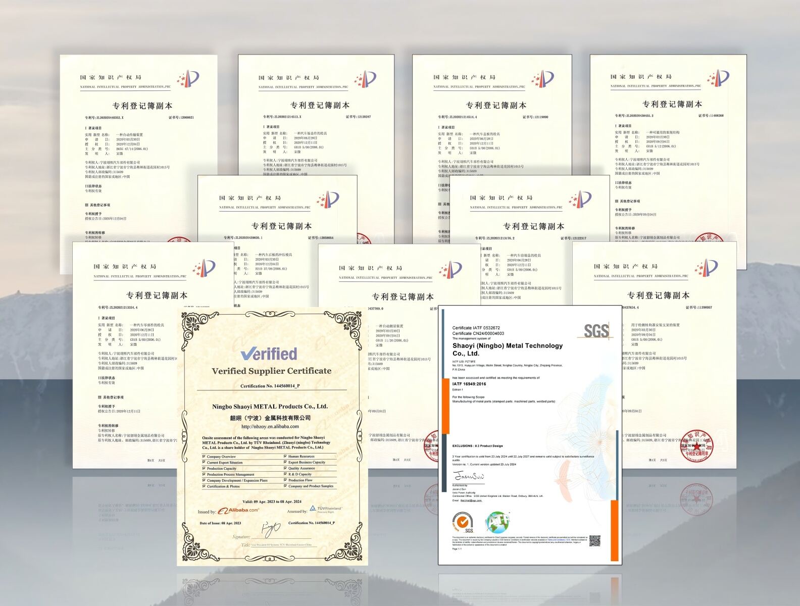
For automotive applications requiring IATF 16949 certification and rigorous SPC quality control, manufacturers like Shaoyi Metal Technology demonstrate how these evaluation criteria come together in practice. Their facility combines certified quality systems with rapid prototyping capabilities and fast lead times—including one-day turnaround for urgent prototypes—while maintaining the documentation and process control automotive supply chains demand. This combination of speed, quality certification, and scalability from prototyping to mass production illustrates what to look for when evaluating potential partners for demanding applications.
The right manufacturing partner becomes an extension of your engineering team—understanding your requirements, proactively identifying potential issues, and consistently delivering parts that meet specifications. That relationship takes time to develop, but it starts with rigorous evaluation of the criteria that actually matter for your specific application.
Making Informed Decisions for Your Custom Parts Project
You've now traveled the complete journey from understanding what custom machined parts are to evaluating manufacturing partners who can bring your designs to life. But information without action remains just that—information. Whether you're an engineer finalizing your first custom component or a procurement professional optimizing your supply chain, the decisions you make from here determine whether your project succeeds or stumbles.
The path from first sketch to factory floor isn't linear. It's iterative, collaborative, and sometimes messy. But armed with the right framework, you can navigate each stage with confidence—transforming complex technical decisions into manageable steps that lead to machining parts that perform exactly as intended.
Key Takeaways for Your Custom Machining Project
Let's distill everything we've covered into the essential principles that drive successful custom cnc machining services outcomes:
The most costly mistakes in custom machining don't happen on the shop floor—they happen during design. Engaging your manufacturing partner early, before designs are finalized, prevents expensive revisions and unlocks optimization opportunities that improve both cost and performance.
This insight reflects a fundamental shift in manufacturing thinking. According to early supplier involvement research, organizations that integrate sourcing and engineering teams from the outset achieve faster time-to-market, reduced costs, and fewer production surprises. When suppliers are engaged throughout the product development process, they contribute valuable expertise that enhances design and functionality while streamlining project execution.
Here's your decision-making framework summarized:
- Understand Your Requirements First: Before requesting quotes or selecting materials, clarify what your part must accomplish. Define critical tolerances versus nice-to-haves. Identify environmental conditions, load requirements, and assembly interfaces. This clarity prevents over-engineering that wastes money and under-engineering that causes failures.
- Match Process to Geometry: CNC milling excels at prismatic shapes and complex 3D surfaces. CNC turning services deliver optimal results for cylindrical components. Swiss machining handles small, precise parts with high aspect ratios. Choosing the right process from the start avoids costly manufacturing workarounds.
- Select Materials Strategically: Balance performance requirements against machinability and cost. Aluminum machines faster and cheaper than stainless steel—but only stainless provides the corrosion resistance certain applications demand. Let function drive material choice, not familiarity or assumption.
- Design for Manufacturability: Avoid sharp internal corners, overly thin walls, and unnecessarily tight tolerances. Each design decision ripples through production—affecting cycle time, tooling costs, and quality outcomes. A custom machine shop can only work with what your design provides.
- Specify Appropriate Precision: Tight tolerances cost money. Focus precision requirements on features critical to function—mating surfaces, bearing bores, assembly interfaces. Standard tolerances for non-critical dimensions reduce costs without compromising performance.
- Verify Partner Capabilities: Certifications, equipment, quality systems, and material expertise all matter. A precision machining service provider qualified for your industry's requirements prevents compliance headaches and quality escapes.
Taking the Next Step
Where you go from here depends on where you are in your project timeline. Different stages demand different actions:
If You're Still Designing:
Now is the optimal time to engage potential manufacturing partners. As collaboration experts note, early collaboration between sourcing and engineering is no longer a luxury but a strategic imperative that can transform product development. Request DFM feedback before finalizing designs. Suppliers possess specialized knowledge about manufacturability that can enhance your design while reducing costs.
If You're Ready for Prototypes:
Prepare complete CAD files with clear tolerance callouts. Identify which features are critical versus those that can accept standard tolerances. Consider whether prototype materials must match production intent or whether faster-machining alternatives can validate form and fit initially. Cnc turning services and milling operations can often deliver prototypes within days when designs are production-ready.
If You're Scaling to Production:
Verify your supplier's capacity matches your volume requirements. Confirm quality systems—especially SPC implementation—can maintain consistency across production runs. Establish clear communication protocols for ongoing orders. Production relationships thrive on predictability and transparency.
Use this action checklist to organize your next steps:
- Complete your requirements documentation—what must the part do, and in what environment?
- Finalize CAD models with appropriate GD&T callouts for critical features
- Identify 2-3 potential manufacturing partners with relevant certifications
- Request DFM feedback and quotes from qualified suppliers
- Compare not just pricing but communication quality, lead time commitments, and scalability
- Plan for prototype validation before committing to production volumes
- Establish quality documentation requirements appropriate to your industry
For readers developing automotive components, chassis assemblies, or high-precision custom metal bushings, the path from prototype to production demands partners who combine speed with certified quality systems. Shaoyi Metal Technology's automotive machining solutions demonstrate this combination—offering one-day lead times for urgent prototypes while maintaining IATF 16949 certification and rigorous Statistical Process Control throughout production scaling. When your project requires both rapid iteration and automotive-grade quality assurance, their capabilities provide a practical starting point for your supplier evaluation.
Custom machined parts represent the intersection of design vision and manufacturing reality. The journey from concept to production-ready components requires technical knowledge, strategic decision-making, and the right partnerships. You now have the foundation to navigate that journey successfully—transforming your requirements into precision components that perform exactly as designed, delivered on time and within budget.
Frequently Asked Questions About Custom Machined Parts
1. How much does it cost to have parts machined?
CNC machining costs vary based on material type, part complexity, tolerances, machine time, and production volume. Hourly rates typically range from $50 to $150 depending on equipment sophistication and precision requirements. Prototype parts cost more per unit due to setup costs spread across fewer pieces, while production volumes significantly reduce per-part pricing. Exotic materials like titanium and tighter tolerances exponentially increase costs. For automotive applications requiring IATF 16949-certified quality, manufacturers like Shaoyi Metal Technology offer competitive pricing with fast lead times starting at one working day for urgent prototypes.
2. How to order custom CNC parts?
Ordering custom CNC parts follows a streamlined process: First, upload your CAD files (STEP, IGES, or native formats) with drawings specifying tolerances and surface finishes. Next, configure your job by selecting materials from metals or engineering plastics, quantity, and finishing options. The manufacturer provides DFM feedback identifying potential issues. After quote approval, production begins with in-process inspections ensuring quality. Parts undergo final inspection before shipping with documentation. For automotive components, certified suppliers like Shaoyi Metal Technology can scale seamlessly from rapid prototyping to mass production while maintaining strict SPC quality control.
3. What is the tolerance for thread holes in CNC machining?
Thread hole tolerances follow the ISO 965-1 standard, which defines tolerance classes for proper bolt and nut engagement. The most common specification is 6H for internal threads (tapped holes) and 6g for external threads (bolts). The number indicates tolerance grade—lower numbers mean tighter tolerances—while the letter indicates position relative to basic size. For standard assemblies, 6H/6g provides optimal balance between reliable fit and manufacturing economy. Critical applications may specify 5H/5g for tighter control, while less demanding situations can use 7H/7g to reduce machining costs.
4. What materials are best for custom machined parts?
Material selection depends on your application's requirements for strength, weight, corrosion resistance, and cost. Aluminum 6061 offers excellent machinability, lightweight properties, and thermal conductivity for brackets and housings. Stainless steel 304 provides superior corrosion resistance for medical and food applications. Titanium delivers exceptional strength-to-weight ratio for aerospace and medical implants. For plastics, Delrin (polyacetal) offers high strength with low friction for gears and bearings, while Nylon provides excellent impact resistance. Bronze excels in bearing applications due to self-lubricating properties. Discuss requirements with your machining partner for optimal recommendations.
5. What certifications should a CNC machine shop have?
Required certifications depend on your industry. ISO 9001:2015 represents the baseline quality management standard any serious manufacturer should hold. Automotive applications require IATF 16949:2016 certification, which encompasses automotive-specific requirements including APQP, PPAP, and SPC methodologies. Aerospace components demand AS9100 certification with its 105 additional requirements beyond ISO 9001. Medical device manufacturing requires ISO 13485 for regulatory compliance. Always verify certificate validity and check for current third-party audit documentation. For automotive projects, partners like Shaoyi Metal Technology maintain IATF 16949 certification with rigorous Statistical Process Control.