 Small batches, high standards. Our rapid prototyping service makes validation faster and easier —

CNC Machined Part Secrets: From Design Flaws To Flawless Orders
What Defines a CNC Machined Part
Ever wondered how a solid block of metal transforms into an intricate aerospace component with near-perfect accuracy? The answer lies in CNC machining—a process that has revolutionized modern manufacturing.
A CNC machined part is a precision component created through computer numerical control machining, a subtractive manufacturing process where computerized controls and machine tools systematically remove material from a workpiece to produce custom-designed shapes and features.
The term "CNC" stands for computer numerical control, referring to the automated system that directs every movement of the cutting tools. Unlike manual machining, where operators guide tools by hand, a CNC machine follows programmed instructions with remarkable precision—often achieving tolerances as tight as ±0.001 inches (±0.025 mm).
From Raw Material to Precision Component
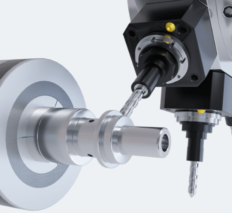
Imagine starting with a simple aluminum block and ending with a complex engine bracket. That transformation happens through a carefully orchestrated process. First, designers create a detailed 3D CAD model containing every dimension and specification. Then, CAM software converts this design into G-code—the programming language that tells the CNC machine exactly where to move, how fast to cut, and how deep to go.
The raw material, called a workpiece or blank, gets secured to the machine bed. From there, the CNC machine takes over, executing thousands of precise movements to shape your cnc machining part exactly as designed. Whether you're working with metals, plastics, wood, or composites, the fundamental process remains consistent.
The Subtractive Manufacturing Principle
Here's what makes machined parts unique: they're created by removing material, not adding it. This subtractive approach differs fundamentally from 3D printing (additive manufacturing) or injection molding (formative manufacturing). Multi-point cutting tools, drill bits, or single-point turning tools chip away at the workpiece layer by layer until only the final shape remains.
This method delivers exceptional surface finishes and dimensional accuracy that many alternative processes simply cannot match. The waste material—called chips or swarf—falls away during cutting, leaving behind your precisely shaped component.
Why CNC Machining Dominates Modern Production
From automotive chassis to surgical instruments, CNC machined parts serve as critical parts of machinery across virtually every industry. Why has this technology become so indispensable?
- Unmatched Precision: Standard tolerances of ±0.005 inches, with precision machining achieving ±0.001 inches
- Material Versatility: Compatible with metals, engineering plastics, composites, and more
- Repeatability: Produce identical components batch after batch
- Complex Geometries: Multi-axis machines create intricate features impossible with manual methods
Industries like aerospace demand extremely tight tolerances for safety-critical components. Medical device manufacturers require biocompatible materials machined to exacting specifications. Automotive suppliers need high-volume consistency. CNC machining delivers on all these requirements, making it the backbone of precision manufacturing worldwide.
Essential Components That Create Precision Parts
So how does a CNC machine actually work? Understanding cnc machine how it works starts with knowing the critical components inside. Each part of the system plays a specific role in transforming your design into a finished component. When these elements work together seamlessly, you get the precision and repeatability that make CNC machining invaluable.
Let's break down the major cnc machine components and explore how each contributes to creating your precision parts.
- Frame/Base: The structural backbone, typically made from cast iron or steel, that absorbs vibration and maintains alignment during cutting operations
- CNC Controller: The machine's brain that interprets G-code commands and coordinates all movement
- Spindle: The rotating assembly that holds and drives cutting tools at speeds up to 40,000+ RPM
- Linear Motion Systems: Ball screws, guide rails, and related components enabling precise axis movement
- Servo Motors and Drives: Closed-loop systems providing accurate speed, torque, and position control
- Automatic Tool Changer (ATC): Carousel or chain magazine that swaps tools without operator intervention
- Coolant System: Delivers lubricating fluid to reduce heat and extend tool life
The Control Panel and Programming Interface
Think of the CNC controller as the conductor of an orchestra—it coordinates every movement with split-second timing. This component interprets the G-code and M-code commands from your CAM software and converts them into precise electrical signals that drive the motors.
Even the most well-built machine can underperform with a weak controller. A capable control system delivers precise motion control, smoothly interpolates complex linear and circular moves, and manages tool paths exactly as programmed. It also compensates for real-world factors like backlash and thermal expansion while continuously monitoring safety conditions.
Modern controllers feature touchscreen interfaces, real-time diagnostics, and connectivity options for remote monitoring. When you're examining the parts of a cnc mill, the controller quality often determines the ceiling for achievable accuracy.
Spindle and Cutting Tool Systems
The spindle is arguably the heart of any CNC machine. This rotating assembly holds and drives the cutting tools, directly influencing your part's surface finish and dimensional accuracy. Spindle configurations vary—belt-driven, direct-drive, or integral motor designs—each offering different performance characteristics.
Key spindle performance factors include:
- Speed Range: From a few hundred RPM for heavy cuts to 40,000+ RPM for fine finishing
- Torque Output: Determines the machine's ability to handle aggressive material removal
- Thermal Stability: Critical for maintaining accuracy during extended operations
- Runout: Lower runout means better surface finish and longer tool life
The tooling for cnc machines matters just as much as the spindle itself. Cutting tools—end mills, drills, reamers, taps—each serve specific purposes. Tool holders secure these cutters in the spindle taper, and their quality directly impacts rigidity and precision. Due to its pivotal role, the spindle is frequently among the costliest cnc components to repair or replace.
Understanding Multi-Axis Movement
Here's where cnc machine movement gets interesting. Basic machines operate on three axes: X (left-right), Y (front-back), and Z (up-down). Linear guide rails and ball screws work together to convert servo motor rotation into smooth, precise linear motion along each axis.
But what about complex geometries? That's where additional axes come into play. Four-axis machines add rotation around the X-axis (A-axis), while five-axis machines include rotation around the Y-axis (B-axis) as well. Five-axis capability allows simultaneous movement of all axes, enabling the creation of intricate contours, undercuts, and compound angles in a single setup.
Why does this matter for your parts? Multi-axis machining reduces setups, improves accuracy by eliminating repositioning errors, and makes possible geometries that would otherwise require multiple operations or specialized fixtures. For complex aerospace brackets or medical implant components, five-axis capability isn't a luxury—it's often a necessity.
The closed-loop feedback from encoders constantly verifies position, allowing servo systems to make micro-adjustments that maintain accuracy throughout the cut. This continuous monitoring is what separates CNC precision from conventional machining methods.
CNC Milling Versus Turning Processes
Now that you understand the components powering CNC machines, let's explore the two primary processes that create your machined parts. Choosing between milling and turning isn't arbitrary—it's driven by your part's geometry, tolerance requirements, and production needs. Get this decision right, and you'll save time, reduce costs, and achieve better results.
The core difference? It comes down to what spins. In CNC turning, the workpiece rotates while a stationary cutting tool shapes the surface. In CNC milling, the cutting tool rotates while the workpiece remains fixed. This fundamental reversal in rotation determines which geometries each process handles best.
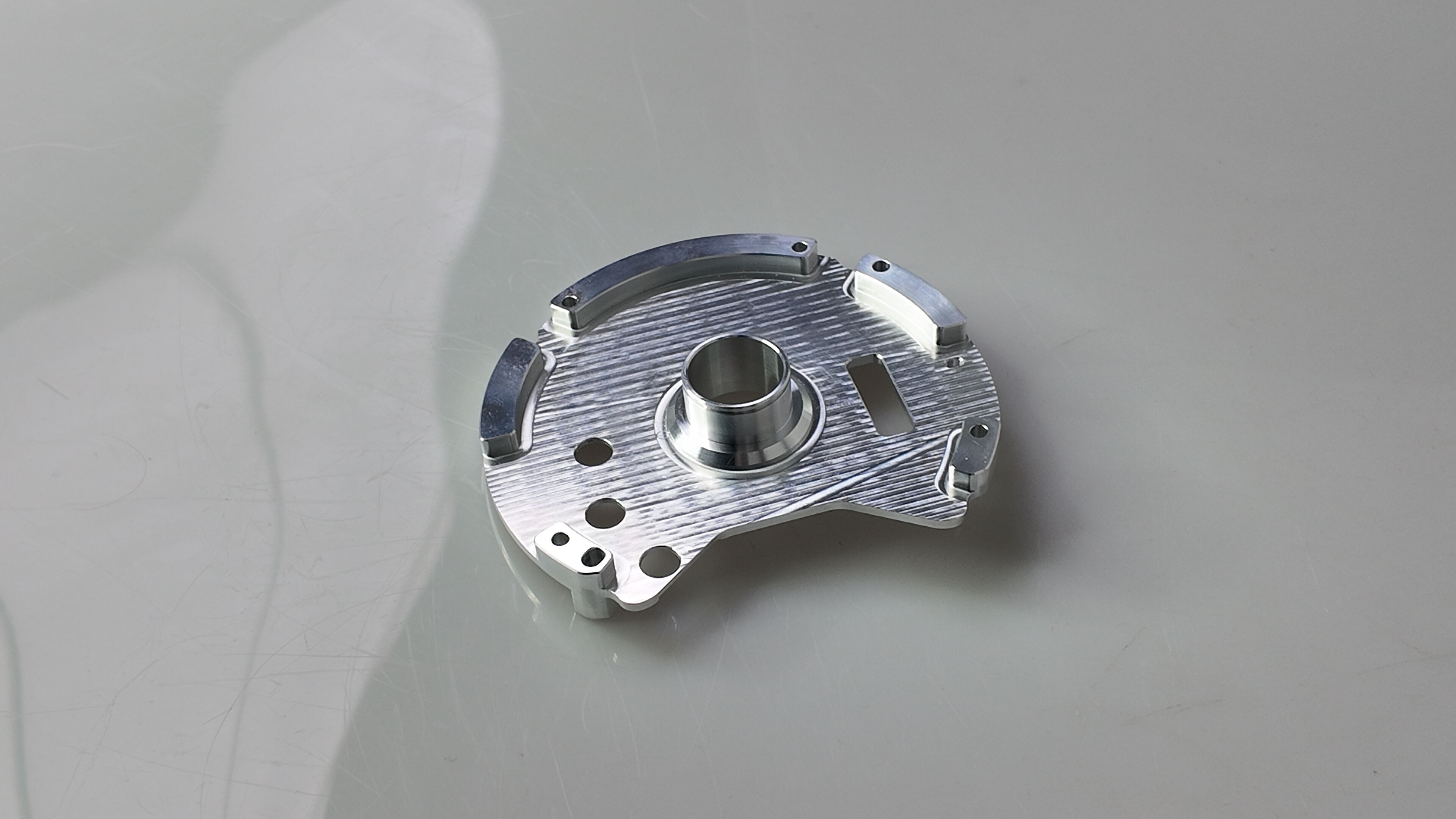
CNC Milling for Complex Prismatic Parts
Imagine machining a housing with pockets, slots, and holes on multiple faces. That's milling territory. CNC milling components excel when your design includes flat surfaces, angular features, and intricate 3D contours that would be impossible to create on a spinning workpiece.
Here's how it works: a rotating multi-point cutter moves along programmed paths—typically X, Y, and Z axes—removing material from your stationary workpiece. The cutter might be an end mill carving pockets, a face mill flattening surfaces, or a ball-nose tool contouring complex curves. Modern 5-axis CNC milling machines can tilt and rotate, accessing virtually any angle without repositioning.
What makes cnc milling parts the right choice?
- Prismatic Geometries: Brackets, housings, engine blocks, and mold cavities
- Multi-Surface Features: Parts requiring machining on several planes
- Complex Contours: Aerospace components, turbine blades, medical implants
- Precision Holes and Slots: Features requiring exact positioning across the part
Milling tolerances typically reach ±0.005 inches for standard work, with precision setups achieving ±0.001 inches or better. Surface finishes of Ra 1–2 µm are achievable with proper tooling and reduced step-over distances during finishing passes.
CNC Turning for Cylindrical Components
Now picture a shaft, bushing, or threaded rod. These parts share something in common—rotational symmetry around a central axis. That's where CNC turning services deliver unmatched efficiency.
In turning, your workpiece spins at high speed while a stationary single-point cutting tool moves along its surface. The part is clamped in a chuck, and as it rotates, the tool follows programmed paths to create external diameters, internal bores, threads, grooves, and facing operations. Modern CNC turning centers equipped with bar feeders can run unattended for high-volume production.
Cnc turned parts shine in these applications:
- Shafts and Rods: Engine shafts, axles, and spindles
- Bushings and Spacers: Concentric components requiring tight roundness
- Threaded Components: Fasteners, fittings, and connectors
- Discs and Flanges: Rotational parts with facing requirements
Turning excels at maintaining concentricity and roundness. Standard tolerances reach ±0.002 inches, with precision turning achieving ±0.001 inches for critical fits. Because chip evacuation is easier with rotating workpieces, turning often delivers cleaner cuts and excellent surface finishes without extensive post-processing.
Choosing the Right Process for Your Part
So which process fits your project? Start with geometry. If your part is primarily round or symmetric along its axis, a cnc turning service will typically be faster and more cost-effective. If your part needs flat faces, pockets, or multi-plane features, milling provides the flexibility you need.
Here's a direct comparison to guide your decision:
| Factor | CNC Milling | CNC Turning |
|---|---|---|
| Part Geometry | Prismatic, flat, multi-faced, complex 3D contours | Cylindrical, conical, rotational symmetry |
| Typical Tolerances | ±0.005" standard; ±0.001" precision | ±0.002" standard; ±0.001" precision |
| Surface Finish | Ra 1–2 µm with finishing strategies | Ra 1–2 µm with optimized feed and insert geometry |
| Common Applications | Housings, brackets, molds, aerospace structures | Shafts, pins, bushings, threaded fittings |
| Setup Complexity | Higher—requires fixturing for multiple faces | Lower—chuck or collet clamping |
| Production Efficiency | Best for complex, low-to-medium volume | Best for high-volume cylindrical parts |
What if your part combines both rotational and prismatic features? Modern mill-turn centers integrate both processes, allowing you to machine a turned shaft with milled keyways or cross-drilled holes in a single setup. This hybrid approach eliminates repositioning errors and dramatically reduces cycle time for complex cnc milled parts that don't fit neatly into one category.
Understanding these process differences empowers you to communicate effectively with your machining partner and make design decisions that optimize both manufacturability and cost. With the right process selected, the next critical decision is choosing the material that will bring your part to life.
Material Selection for CNC Machined Components
You've selected your machining process—now comes an equally critical decision. What material will become your finished part? This choice influences everything from machining speed and tool wear to surface finish quality and final cost. Pick the wrong material, and you'll face longer cycle times, excessive tool replacement, or parts that don't perform as expected.
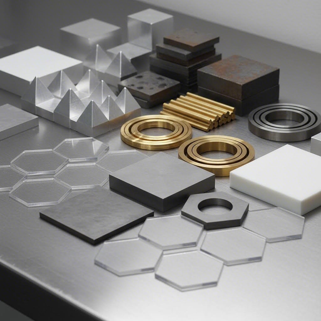
Whether you're machining metals for structural strength or engineering plastics for lightweight applications, understanding each material's characteristics helps you balance performance requirements against budget constraints. Let's explore your options.
Aluminum and Steel for Structural Applications
When strength and reliability matter, metals remain the go-to choice. But not all metals machine the same way—or cost the same.
Aluminum is the workhorse of aluminum machining operations. Its low density (2.7 g/cm³) makes it ideal for weight-sensitive applications like automotive brackets and consumer electronics housings. What makes it so popular? Excellent machinability. Aluminum cuts quickly, generates less heat, and extends tool life compared to harder metals. Common alloys like 6061-T6 offer a good balance of strength, corrosion resistance, and weldability, while 7075 provides higher strength for aerospace applications.
According to material comparison data, aluminum 6061-T651 delivers tensile strength of 40 ksi (276 MPa) with 17% elongation—strong enough for most structural components while remaining easy to machine.
Steel offers superior strength and hardness when applications demand it. Mild steels (1018, 1045) machine reasonably well and accept heat treatment for increased hardness. Stainless steels (303, 304, 316) add corrosion resistance but require slower speeds and specialized tooling. Expect higher tool wear and longer cycle times compared to aluminum—but for load-bearing components, structural frames, or wear surfaces, steel's performance justifies the added machining cost.
Brass deserves mention for its exceptional machinability. Free-cutting brass machines faster than almost any other metal, making it cost-effective for electrical connectors, fittings, and decorative components. Its natural corrosion resistance eliminates the need for coatings in many applications.
Titanium sits at the performance extreme. Machining titanium demands slower speeds, rigid setups, and carbide tooling—but the results justify the effort for aerospace and medical applications. With tensile strength of 138 ksi (951 MPa) and excellent corrosion resistance, titanium delivers where no other material can. Its biocompatibility makes it essential for surgical implants, while its high strength-to-weight ratio serves aircraft components.
The tradeoff? Titanium's hardness causes faster tool wear, and its low thermal conductivity means heat concentrates at the cutting edge. Expect machining costs 5-10 times higher than aluminum for comparable parts.
Engineering Plastics from Delrin to Polycarbonate
Not every application needs metal. Engineering plastics offer lightweight alternatives with unique properties—and often machine faster than metals.
So what is delrin? It's a brand name for acetal plastic (polyoxymethylene or POM), known for its exceptional dimensional stability, low friction, and excellent machinability. Delrin plastic machines beautifully, holding tight tolerances while producing smooth surface finishes. You'll find it in gears, bearings, bushings, and precision components where metal would add unnecessary weight or require lubrication.
Nylon for machining offers similar versatility with added toughness. It absorbs vibration, resists abrasion, and works well for wear components like rollers and guides. However, nylon absorbs moisture—something to consider for dimensionally critical applications in humid environments.
Acrylic (PMMA) provides optical clarity when transparency matters. It machines well but requires careful handling to prevent cracking, especially around thin features. Medical devices, displays, and light guides often use machined acrylic.
Polycarbonate PC combines impact resistance with good machinability. It's tougher than acrylic and handles stress better, making it suitable for safety shields, electrical housings, and components exposed to impact loading. Unlike acrylic, polycarbonate bends before breaking.
Material Selection Impact on Cost and Quality
Your material choice directly affects your bottom line. Here's how the factors stack up:
| Material | Machinability Rating | Typical Applications | Relative Cost | Key Properties |
|---|---|---|---|---|
| Aluminum 6061 | Excellent | Brackets, housings, heat sinks | Low | Lightweight, corrosion resistant, weldable |
| Aluminum 7075 | Good | Aerospace components, high-stress parts | Medium | High strength, fatigue resistant |
| Steel 1018 | Good | Shafts, pins, general structural | Low | Weldable, case-hardenable |
| Stainless 303 | Moderate | Fittings, fasteners, food equipment | Medium | Corrosion resistant, free-machining grade |
| Stainless 316 | Difficult | Medical, marine, chemical processing | Medium-High | Superior corrosion resistance |
| Brass 360 | Excellent | Electrical, plumbing, decorative | Medium | Free-cutting, corrosion resistant |
| Titanium Ti-6Al-4V | Difficult | Aerospace, medical implants, marine | High | High strength-to-weight, biocompatible |
| Delrin (Acetal) | Excellent | Gears, bearings, precision parts | Low-Medium | Low friction, dimensionally stable |
| Nylon 6/6 | Good | Bushings, rollers, wear components | Low | Tough, abrasion resistant, self-lubricating |
| Polycarbonate | Good | Guards, enclosures, optical components | Low-Medium | Impact resistant, transparent |
| Acrylic (PMMA) | Good | Displays, lenses, light guides | Low | Optically clear, UV stable |
What drives these cost differences? Several factors compound:
- Raw Material Cost: Titanium and specialty alloys cost significantly more per pound than aluminum or plastics
- Machining Speed: Harder materials require slower feed rates, increasing cycle time
- Tool Wear: Difficult-to-machine materials consume more cutting tools, adding replacement costs
- Post-Processing: Some materials require additional heat treatment, anodizing, or surface finishing
For budget-conscious projects, aluminum and acetal plastic deliver excellent performance at reasonable cost. When strength-to-weight ratio is paramount, titanium justifies its premium. And when corrosion resistance matters more than machining economy, stainless steel finds its place.
Understanding these tradeoffs helps you specify the right material from the start—avoiding redesigns, reducing costs, and ensuring your finished parts meet performance requirements. With your material selected, the next step is designing your part for optimal manufacturability.
Design Rules That Optimize Manufacturability
You've selected your material and machining process. Now comes the step that separates smooth production runs from costly redesigns—designing your part for manufacturability. The decisions you make at the CAD stage directly determine how efficiently your cnc machine parts can be produced, what tolerances are achievable, and ultimately, how much you'll pay.
Design-for-manufacturability (DFM) isn't about limiting creativity. It's about understanding what cutting tools can physically accomplish and designing within those boundaries. Follow these guidelines, and you'll reduce machining time, extend tool life, and avoid the frustrating back-and-forth that delays projects.
Critical Wall Thickness and Feature Depth Rules
Thin walls vibrate. Vibrating walls produce chatter marks, dimensional errors, and sometimes outright failure. That's why wall thickness minimums exist—and ignoring them invites problems.
According to industry guidelines, here are the practical thresholds:
- Metal Parts: Minimum 0.8 mm (0.03 in) wall thickness recommended; 0.5 mm feasible with careful machining
- Plastic Parts: Minimum 1.5 mm (0.06 in) recommended; 1.0 mm feasible for rigid plastics
- Unsupported Spans: Add ribs or shorten spans when walls exceed 8:1 height-to-thickness ratio
Why the difference between metals and plastics? Plastics are prone to warping from residual stresses and softening from heat buildup during cutting. Thicker walls maintain rigidity throughout the machining cycle.
Feature depth follows similar logic. Deep pockets and cavities push cutting tools to their limits. The recommended rule? Limit blind pocket depth to 3-4 times the tool diameter. Go deeper, and tool deflection increases, surface quality suffers, and tolerances become harder to hold.
- Standard Cavities: Maximum depth of 4× cavity width for reliable results
- Deep Cavities: Depths beyond 6× tool diameter require specialized extended-reach tooling
- Hole Depth: Standard drilling reaches 4× nominal diameter; specialized bits extend to 40× diameter
Need deeper features? Consider opening one side of the pocket for side access, using stepped depths, or splitting the part into assemblies. These alternatives often cost less than fighting physics with extended tooling.
Internal Corners and Tool Access Considerations
Here's a reality that catches many designers off guard: CNC tools are round. That means internal corners can never be perfectly sharp—they'll always carry a radius equal to at least the tool radius.
The practical guidance? Specify internal corner radii at least one-third the cavity depth. This allows properly sized tools to reach full depth without deflection issues. Here's how tool size translates to minimum fillets:
| Tool Diameter | Tool Radius | Recommended Min. Internal Fillet |
|---|---|---|
| 3 mm | 1.5 mm | ≥ 1.5–2.0 mm |
| 6 mm | 3.0 mm | ≥ 3.0–3.5 mm |
| 10 mm | 5.0 mm | ≥ 5.0–6.0 mm |
Why does this matter so much for complex machined parts? Tiny internal radii force machinists to use small-diameter tools. Small tools mean slower feed rates, more passes, and longer cycle times. Relaxing corner radii—even slightly—often delivers the biggest cost savings in any DFM review.
For undercuts (features that can't be accessed directly from above), standard T-slot and dovetail cutters handle most requirements. Keep undercut widths between 3-40 mm using standard sizes, and add clearance equal to at least 4× the undercut depth between machined walls.
Design Decisions That Reduce Manufacturing Cost
Every design choice carries a cost consequence. Smart decisions at the CAD stage compound into significant savings at production scale. Here's where to focus:
Tolerances: The biggest cost driver you control. Default to ±0.13 mm (±0.005 in) for general features and reserve tighter tolerances—±0.05 mm for precision fits, ±0.01-0.02 mm for critical bores—only where function demands them. Over-tolerancing everything increases inspection time and machining complexity without adding value.
Threads: Keep effective thread length to 2-3× the hole diameter. Deeper threads add machining time without increasing strength. For blind threaded holes, leave 1.5× nominal diameter of unthreaded relief at the bottom so taps don't bottom out.
Setups: Each time a part gets flipped or re-clamped, positional uncertainty increases and costs accumulate. Design parts that can be machined in three setups or fewer whenever possible. Align critical features to shared datums so they can be cut in the same clamping.
Standard Tooling: Match hole diameters and slot widths to standard drill and cutter sizes. Non-standard dimensions require custom tools or interpolated milling—both add time and expense. When specifying threads, stick to common sizes (M3, M4, M5, M6, M8) that every shop can cut with standard taps.
For cnc prototyping and custom machined parts, these guidelines translate directly to faster quotes, shorter lead times, and lower piece prices. Precision machining services appreciate well-designed parts—and often prioritize them when schedules get tight.
The bottom line? DFM isn't about compromise. It's about designing parts that cutting tools can produce efficiently. Master these rules, and you'll spend less time waiting for revised quotes and more time with finished parts in hand. With your design optimized, understanding how different industries apply these principles reveals even more opportunities to refine your approach.
Industry Applications from Automotive to Medical
Understanding design rules is one thing—seeing how they translate into real-world applications is another. Different industries demand vastly different specifications from their CNC machined parts. What passes inspection in one sector might be rejected outright in another. So where do these precision components actually end up?
From engine blocks powering your daily commute to surgical implants restoring patient mobility, CNC machining serves as the manufacturing backbone across industries with zero tolerance for failure. Each sector brings unique requirements—and understanding them helps you specify parts that meet the right standards from the start.
Automotive Chassis and Powertrain Components
The automotive industry runs on consistency. When you're producing thousands of identical components daily, every part must fit perfectly—because assembly lines don't wait for rework. CNC machined automotive components include everything from engine blocks and transmission housings to suspension brackets and brake system parts.
What makes automotive machining distinct?
- High-Volume Repeatability: Thousands of identical parts with consistent dimensional accuracy across every production run
- Tight Cost Controls: Optimized cycle times and material utilization to meet competitive price points
- IATF 16949 Certification: The automotive quality management standard that ensures process control and traceability
- Statistical Process Control (SPC): Real-time monitoring that catches trends before they become defects
Typical tolerances range from ±0.05 mm for general structural components to ±0.01 mm for precision fits in powertrain assemblies. Materials span aluminum alloys for lightweight chassis parts, hardened steels for wear surfaces, and engineering plastics for interior mechanisms.
Aerospace Structural and Engine Parts
When failure isn't an option, aerospace cnc machining sets the standard. Aircraft components face extreme forces, temperature swings, and regulatory scrutiny that far exceed automotive requirements. A single flaw in a turbine blade or structural bracket can lead to catastrophic consequences.
Aerospace machining demands tolerances that push equipment to its limits. According to industry inspection standards, aerospace parts often require tolerances within ±0.0001 inches (±0.0025 mm)—ten times tighter than standard automotive work. Every dimension gets verified, every surface inspected.
- AS9100 Certification: The aerospace-specific quality management standard building on ISO 9001
- Material Traceability: Full documentation from raw material certification through final inspection
- First Article Inspection (FAI): Comprehensive verification that initial parts match design specifications exactly
- Fatigue and Stress Testing: Verification that parts withstand repeated loading cycles
Common cnc machining aerospace applications include landing gear components, hydraulic manifolds, engine mounts, and structural brackets. Materials favor titanium and high-strength aluminum alloys (7075-T6) where strength-to-weight ratio determines flight performance.
Medical Device and Implant Manufacturing
Medical machining adds a dimension beyond dimensional accuracy—biocompatibility. Parts that contact human tissue must be manufactured from materials the body won't reject, with surface finishes that prevent bacterial growth and promote healing.
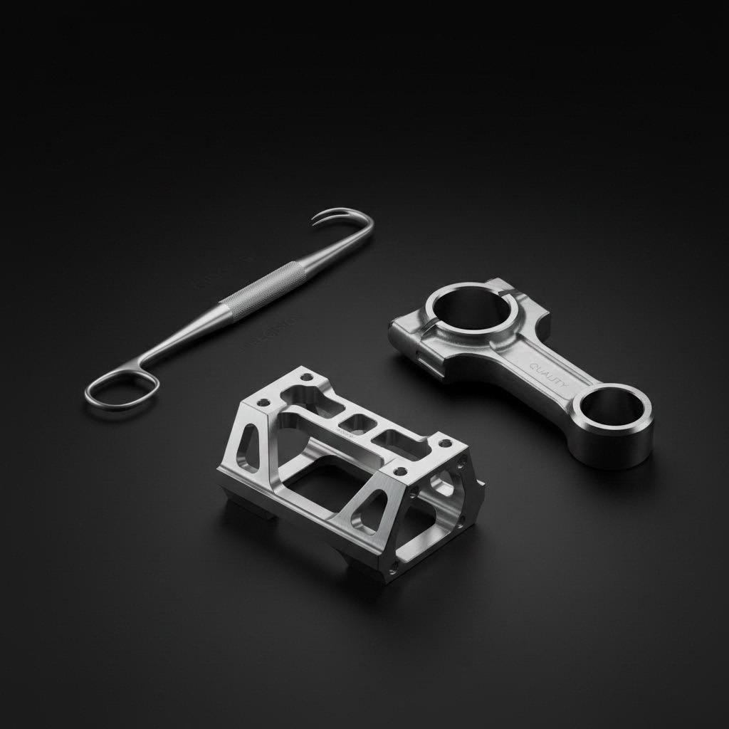
Medical device machining encompasses surgical instruments, diagnostic equipment housings, and implantable components. Each category carries distinct requirements:
- Surgical Instruments: Stainless steel construction with mirror-polished surfaces for sterilization
- Orthopedic Implants: Titanium or cobalt-chrome alloys machined to exact patient specifications
- Diagnostic Equipment: Precision housings and mechanisms with micron-level positioning accuracy
- Drug Delivery Devices: Biocompatible plastics and metals with tight tolerances for controlled dosing
Surface finish matters critically in medical applications. As inspection standards note, implantable devices need flawless surfaces where roughness values (Ra) are measured and verified. Profilometers quantify surface texture while visual inspection under magnification catches micro-burrs that could irritate tissue.
ISO 13485 certification governs medical device manufacturing, requiring documented processes, validated equipment, and complete traceability. Unlike automotive where SPC monitors batch production, medical machining often demands 100% inspection—every single part verified before release.
What unites these diverse industries? Each relies on CNC machining to deliver parts that perform exactly as designed, every time. The certifications differ, the tolerances vary, and the materials change—but the fundamental need for precision, repeatability, and documented quality remains constant. Understanding these industry-specific demands helps you communicate requirements clearly and select suppliers equipped to meet them. But what happens when parts don't meet specifications? Recognizing common defects—and their causes—gives you the knowledge to prevent quality issues before they occur.
Troubleshooting Common Part Defects
Even the most advanced CNC equipment can produce flawed parts. Whether you're receiving machined metal parts from a supplier or running production in-house, knowing how to identify defects—and understanding what causes them—puts you in control. The difference between a scrapped batch and a successful project often comes down to recognizing problems early and addressing root causes before they compound.
What kinds of issues should you watch for? Surface finish problems, dimensional inaccuracies, burrs, and stress-related failures top the list. Let's break down each defect category, explore what triggers them, and discuss how quality verification catches issues before parts leave the shop.
Surface Finish Defects and Their Causes
You specified Ra 1.6 µm on your drawing, but the parts arrived with visible tool marks and an inconsistent texture. What went wrong? Surface finishes depend on a chain of factors—and when any link breaks, quality suffers.
Common surface finish problems include:
- Chatter Marks: Wavy patterns caused by vibration between the cutting tool and workpiece. According to machining defect research, chatter occurs when the tool or workpiece oscillates uncontrollably, leading to poor surface finish and accelerated tool wear.
- Feed Lines: Visible ridges from excessive feed rates or worn tool edges
- Scratches: Surface damage from chip re-cutting or improper handling
- Dull or Cloudy Surfaces: Result of worn tools or incorrect cutting parameters
Prevention starts with rigid setups. Secure workpiece clamping, balanced toolholders, and appropriate speeds reduce vibration at the source. Using proper cutting parameters—matching feed rate and depth of cut to material and tool geometry—eliminates most feed line issues. When precision cnc machined components demand flawless surface finishes, fresh cutting inserts and optimized finishing passes make the difference.
Dimensional Accuracy and Tolerance Failures
Dimensional inaccuracies represent the most common rejection reason for metal machined parts. When machined components fall outside specified tolerances, assemblies don't fit, performance degrades, and rework costs accumulate.
What causes parts to miss dimensions?
- Tool Wear: Cutting edges degrade over time, causing gradual dimensional drift
- Thermal Expansion: Heat buildup during machining causes workpiece and machine components to grow
- Machine Calibration: Axis positioning errors from worn ballscrews or misaligned guideways
- Workpiece Deflection: Thin features bending under cutting forces
- Tool Deflection: Long or slender tools bending away from programmed paths
According to quality control standards, if no specific tolerance is provided, international standards typically allow ±0.1 mm. For tighter requirements, shops must implement proactive measures: regular tool monitoring, thermal stabilization periods, and in-process measurement to catch drift before it exceeds limits.
Burrs—those unwanted raised edges remaining after machining—create assembly problems and safety hazards. They can interfere with part fit, damage mating surfaces, and even cause injury during handling.
| Defect Type | Common Causes | Prevention Methods | Detection Approach |
|---|---|---|---|
| Chatter/Vibration Marks | Unstable setups, incorrect speeds, tool overhang | Rigid clamping, reduced speeds, shorter tool projection | Visual inspection, surface profilometry |
| Dimensional Errors | Tool wear, thermal expansion, calibration drift | Regular tool changes, thermal stabilization, periodic calibration | CMM measurement, go/no-go gauges |
| Burrs | Dull tools, improper exit angles, insufficient support | Sharp tooling, optimized tool paths, deburring operations | Visual inspection, tactile checks |
| Tool Marks | Excessive feed rates, worn inserts, wrong geometry | Reduced feed rates, fresh inserts, appropriate tool selection | Visual inspection, surface roughness measurement |
| Material Stress/Warping | Residual stress release, aggressive material removal, thin walls | Stress-relieved stock, balanced machining sequences, adequate wall thickness | CMM verification, flatness measurement |
Quality Verification and Inspection Methods
How do you know parts actually meet specifications? Reliable quality verification combines multiple inspection approaches, each suited to different feature types.
Coordinate Measuring Machines (CMM) serve as the gold standard for dimensional verification. These precision instruments use touch probes or optical sensors to map part geometry in three dimensions, comparing measured values against CAD models or drawing specifications. For cnc machined components requiring geometric tolerancing—flatness, perpendicularity, position—CMM provides the definitive answer.
According to inspection best practices, CMM inspection and GD&T principles play a vital role in evaluating complex shapes, ensuring parts meet both dimensional and geometric standards.
Surface Roughness Measurement quantifies what visual inspection can only estimate. Profilometers trace stylus tips across surfaces, measuring peak-to-valley heights and calculating Ra, Rz, and other roughness parameters. When drawings specify surface finishes, profilometry provides objective verification.
Statistical Process Control (SPC) catches problems before they become defects. By sampling parts throughout production runs and plotting measurements on control charts, machinists identify trends—tool wear, thermal drift, material variation—before dimensions drift out of tolerance. This proactive approach, recommended by quality standards, ensures consistency across every cnc machined part in the batch.
For precision cnc machined components, combining these methods creates layered verification. First-article inspection verifies setup accuracy. In-process sampling tracks stability. Final inspection confirms shipment-ready quality. Together, they transform quality from reactive rejection into proactive prevention.
Understanding these defects and verification methods arms you with the knowledge to evaluate supplier capabilities and set realistic expectations. But what if CNC machining isn't the right process for your application? Comparing alternatives reveals when different manufacturing methods might better serve your needs.
CNC Machining Versus Alternative Methods
You've identified a defect-free path to quality parts—but is CNC machining actually the right process for your project? This question matters more than most buyers realize. Choosing the wrong manufacturing method wastes budget, extends timelines, and sometimes produces parts that don't perform as expected.
The reality? Metal cnc machining excels in many scenarios but falls short in others. Understanding where CNC fits—and where alternatives like 3D printing, injection molding, or casting make more sense—helps you make informed decisions that optimize both cost and quality.
CNC Versus 3D Printing for Prototypes
When you need a cnc prototype quickly, both CNC machining and 3D printing can deliver. But which serves your needs better? The answer depends on geometry, material requirements, and what you're testing.
CNC prototype machining starts with a solid block and removes material to create your part. This subtractive approach delivers production-grade materials and tight tolerances—your prototype behaves exactly like the final product. According to manufacturing comparison data, CNC parts can ship from one business day with tolerances reaching ±0.025mm and surface finishes as smooth as Ra 0.8 μm.
3D printing builds parts layer by layer from powder or filament. Additive processes like DMLS (Direct Metal Laser Sintering) excel at geometries CNC can't touch—internal channels, lattice structures, and organic shapes with no tool access requirements. For titanium dmls/cnc comparisons, DMLS creates complex lightweight structures while CNC delivers tighter tolerances on simpler geometries.
When should you choose each?
- Choose CNC Prototyping When: You need production materials, tight tolerances (±0.025mm), smooth surfaces, or functional testing with real-world performance
- Choose 3D Printing When: Your design includes internal features, complex organic shapes, or you're iterating rapidly on form-factor before committing to final geometry
For metal machining applications, CNC typically wins on surface finish and dimensional accuracy. DMLS parts arrive with rougher surfaces (Ra 10-15 μm) requiring post-processing for precision fits. But when part consolidation eliminates assembly steps or complex internal cooling channels improve performance, additive manufacturing justifies its higher per-part cost.
When Injection Molding Beats CNC Machining
Here's the economics that every buyer should understand: CNC machining cost per part stays relatively flat regardless of quantity. Injection molding has high upfront tooling costs but dramatically lower per-part pricing at volume. Somewhere between these curves lies your break-even point.
According to manufacturing process comparisons, injection molding typically becomes economical starting around 1,000 pieces. Below that threshold, tooling costs—often exceeding $1,000 for aluminum molds—dominate your budget. Above it, each additional part costs a fraction of what CNC would charge.
But volume isn't the only factor. Consider these decision criteria:
- Design Stability: Injection molds lock in your design. Changes require expensive tool modifications. CNC handles design iterations with just a program update.
- Lead Time: CNC delivers in 1-2 weeks. Injection mold fabrication takes 3-5 weeks before first parts ship.
- Material Options: Both processes support wide material ranges, though CNC plastic machining handles production-grade engineering plastics that match injection-molded properties.
- Geometric Constraints: Injection molding requires draft angles, uniform wall thickness, and mold-friendly geometry. CNC handles undercuts and varying thicknesses without issue.
The practical guidance? Use CNC for prototype machining and low-volume production while you validate designs. Transition to injection molding when designs freeze and quantities justify tooling investment.
The Casting Alternative for Complex Parts
What about parts too complex for efficient CNC machining but produced in volumes too low for injection molding? Casting processes—particularly urethane casting for plastics and investment casting for metals—fill this gap.
Urethane casting creates silicone molds from master patterns, then produces parts from polyurethane resins. This process handles complex geometries including undercuts that would require expensive CNC setups. Lead times match CNC at 1-2 weeks, and per-part costs fall between CNC and injection molding for quantities of 10-100 pieces.
Investment casting serves similar purposes for metal parts. Complex geometries, internal features, and near-net shapes reduce machining requirements. For parts requiring metal properties but facing CNC limitations, casting followed by finish machining often provides the optimal balance.
Here's how these methods compare across key decision factors:
| Factor | CNC Machining | 3D Printing (DMLS) | Injection Molding | Urethane Casting |
|---|---|---|---|---|
| Volume Suitability | 1-1,000 parts | 1-100 parts | 1,000+ parts | 10-100 parts |
| Per-Part Cost Trend | Flat (consistent) | High (consistent) | Decreasing with volume | Moderate (consistent) |
| Typical Lead Time | 1-2 weeks | 1-3 weeks | 3-5 weeks (with tooling) | 1-2 weeks |
| Geometric Capability | External features, limited internal | Complex internal, lattices, organic | Mold-friendly geometry required | Complex shapes, undercuts |
| Material Range | Metals and plastics | Metals only | Thermoplastics | Polyurethane resins |
| Tolerance Capability | ±0.025mm achievable | ±0.1mm standard | ±0.05mm typical | ±0.15mm typical |
| Surface Finish | Ra 0.8 μm achievable | Ra 10-15 μm (post-processing needed) | Mold texture dependent | Mold texture dependent |
What's the bottom line? Match your manufacturing method to your project requirements:
- Need tight tolerances and production materials? CNC machining delivers
- Need complex internal features or topology-optimized designs? Consider DMLS
- Producing thousands of identical plastic parts? Injection molding wins economically
- Need moderate quantities with complex geometry? Urethane casting bridges the gap
Many successful products combine multiple methods throughout their lifecycle. Prototype machining validates designs, urethane casting supports initial market testing, and injection molding scales for volume production. Understanding each method's strengths helps you deploy the right process at the right time—optimizing both development speed and total cost. With your manufacturing method selected, the final step is executing a successful order that delivers parts matching your specifications exactly.
How to Successfully Order CNC Machined Parts
You've selected your manufacturing method and designed for manufacturability. Now comes the moment of truth—placing an order that results in parts matching your exact specifications. This step separates frustrating back-and-forth revisions from smooth, first-time-right production runs. Whether you're searching for cnc machining near me or evaluating global suppliers, the same fundamentals apply.
Getting custom cnc parts right requires clear communication, proper documentation, and careful supplier evaluation. Miss any of these elements, and you'll spend weeks chasing corrections instead of moving your project forward. Let's walk through the process that delivers flawless results.
Preparing Technical Documentation for Quotes
Your technical drawings tell the machinist exactly what you need—but only if they contain the right information presented clearly. According to manufacturing documentation best practices, modern manufacturing starts with a 3D CAD model, but technical drawings remain essential for communicating critical dimensions, tolerances, and special requirements.
What makes documentation quote-ready?
- Provide Complete 3D CAD Files: STEP or IGES formats work universally across different CAM systems. Include native files when possible for suppliers using compatible software.
- Create Annotated Technical Drawings: Add dimensions to functional features, specify tolerances where they matter, and call out surface finish requirements using standard notation (Ra values).
- Dimension Measurable Features: As documentation guidelines emphasize, dimension physical features rather than centerlines or modeling planes whenever possible. This simplifies inspection and reduces interpretation errors.
- Include Clear Notes: Specify material grade (not just "aluminum" but "6061-T6"), thread standards, heat treatment requirements, and any finishing operations needed.
- Identify Critical Features: Use GD&T symbols or clear notes to highlight which dimensions require tightest control. This helps machinists prioritize setup accuracy where it matters most.
The goal? Leave no room for interpretation. A brief note explaining a feature's purpose helps machinists make informed programming decisions. When seeking a cnc quote online, complete documentation speeds response time and produces more accurate pricing.
Evaluating Supplier Capabilities and Certifications
Not every cnc service matches every project. Finding a machinist near me might work for simple brackets, but complex automotive or aerospace components demand verified capabilities. How do you separate capable suppliers from those who'll struggle with your requirements?
Start with certifications. According to supplier evaluation research, certifications like ISO 9001, IATF 16949, and AS9100 signal a supplier's commitment to quality, traceability, and process control. These standards ensure your parts meet tight tolerances while reducing production risks.
Here's what each certification tells you:
| Certification | Industry Focus | What It Ensures |
|---|---|---|
| ISO 9001 | General Manufacturing | Documented quality control processes, continuous improvement practices |
| IATF 16949 | Automotive | Defect prevention, statistical process control, lean production systems |
| AS9100 | Aerospace/Defense | Rigorous traceability, process validation, safety-critical protocols |
| ISO 13485 | Medical Devices | Biocompatibility compliance, regulatory traceability |
For automotive applications, IATF 16949 certification isn't optional—it's the baseline that proves suppliers can consistently deliver parts meeting stringent standards. This certification adds layers of defect prevention through statistical process control (SPC), production part approval processes (PPAP), and advanced product quality planning (APQP).
Beyond certifications, evaluate these capabilities:
- Equipment: Do they have the axis count and envelope size your parts require?
- Inspection: CMM capabilities, surface profilometry, and documented inspection protocols
- Material Experience: Verified track record with your specific material grades
- Lead Time Reliability: On-time delivery history and capacity for your timeline
For example, Shaoyi Metal Technology exemplifies what to look for in an automotive machining partner—IATF 16949 certification backed by strict Statistical Process Control, with lead times as fast as one working day for urgent requirements. Their capability to scale from rapid prototyping through mass production demonstrates the integrated approach that minimizes supply chain complexity.
From Prototype to Production Scaling
The journey from first article to full production challenges many buyer-supplier relationships. Quantities change, timelines compress, and quality expectations remain constant. How do you navigate this transition smoothly?
Follow this ordering checklist to set your project up for success:
- Request Prototype Quantities First: Validate fit, function, and finish before committing to production volumes. This catches design issues when changes are still affordable.
- Conduct First Article Inspection (FAI): Verify that initial parts match specifications exactly. Document any deviations and resolve them before proceeding.
- Establish Quality Requirements: Define inspection sampling rates, acceptable quality levels (AQL), and documentation requirements upfront.
- Confirm Production Capacity: Ensure your supplier can meet volume requirements without sacrificing quality or lead times.
- Set Communication Protocols: Establish points of contact, response time expectations, and escalation procedures.
- Plan for Traceability: Require lot tracking and inspection records for regulatory compliance or warranty protection.
Statistical Process Control becomes especially critical during production scaling. SPC tracks dimensional trends throughout runs, catching tool wear or thermal drift before parts exceed tolerances. Suppliers implementing SPC deliver consistent quality across every batch—not just the samples they inspect.
What happens when you need both speed and scale? Certified suppliers bridge this gap by maintaining capacity for rapid prototyping alongside production-ready equipment. This integration eliminates the risk of transitioning between different shops—and the quality variations that often follow.
The bottom line? Successful ordering combines thorough documentation, verified supplier capabilities, and structured scaling processes. Whether you're sourcing online machining quotes or building long-term partnerships with cnc near me suppliers, these fundamentals ensure your CNC machined parts arrive exactly as designed—every time.
Frequently Asked Questions About CNC Machined Parts
1. What are CNC machined components?
CNC machined components are precision parts created through computer numerical control machining—a subtractive manufacturing process where computerized controls direct cutting tools to systematically remove material from a workpiece. This automated process transforms raw materials like metals, plastics, and composites into custom-designed shapes with tolerances as tight as ±0.001 inches. Industries from automotive to aerospace rely on CNC machining for consistent, high-precision parts that manual methods cannot replicate.
2. How much does it cost to get a part CNC machined?
CNC machining costs vary based on material choice, part complexity, tolerances, and quantity. Hourly rates typically range from $50 to $150 depending on equipment and precision requirements, with setup fees starting at $50 and exceeding $1,000 for complex jobs. Per-part costs remain relatively flat regardless of volume, making CNC economical for 1-1,000 pieces. Choosing easier-to-machine materials like aluminum over titanium, relaxing non-critical tolerances, and designing for manufacturability significantly reduce costs.
3. What are the 7 major parts of a CNC machine?
The seven essential CNC machine components include: the Machine Control Unit (MCU) that interprets G-code commands; input devices where programs are loaded; the drive system with servo motors and ball screws enabling precise movement; machine tools including spindle and cutting implements; feedback systems with encoders for position verification; the bed and table providing structural support; and the cooling system that reduces heat and extends tool life. Together, these components enable the precision and repeatability that define CNC machining.
4. What is the difference between CNC milling and CNC turning?
The fundamental difference lies in what rotates. In CNC milling, a rotating cutting tool moves against a stationary workpiece to create prismatic parts with flat surfaces, pockets, and complex 3D contours. In CNC turning, the workpiece rotates while a stationary tool shapes it—ideal for cylindrical components like shafts and bushings. Milling suits housings and brackets; turning excels at concentric parts requiring tight roundness. Modern mill-turn centers combine both processes for complex geometries in a single setup.
5. How do I choose the right CNC machining supplier for automotive parts?
For automotive applications, prioritize suppliers with IATF 16949 certification—the industry-standard quality management system ensuring defect prevention and statistical process control. Evaluate their inspection capabilities (CMM, surface profilometry), material experience with your specific grades, and lead time reliability. Certified suppliers like Shaoyi Metal Technology demonstrate ideal capabilities with IATF 16949 certification, strict SPC implementation, and lead times as fast as one working day, supporting seamless scaling from prototyping to mass production.